
4. EQUIPMENT INSTALLATION TO THE ROBOT
4.1.FLANGE DIMENSION
This section describes the mounting face dimension of the end effector. Consider the depth of the screw holes and pin holes sufficiently before choose the length of the bolts and pins. Antirust measures of screws, grippers, etc., should be considered as well.
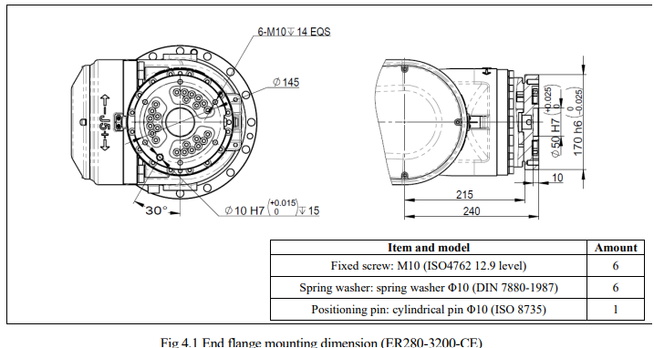
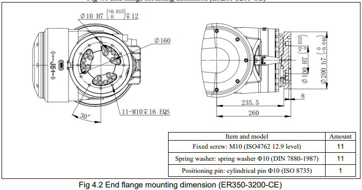
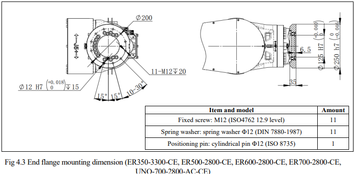
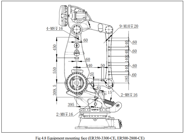
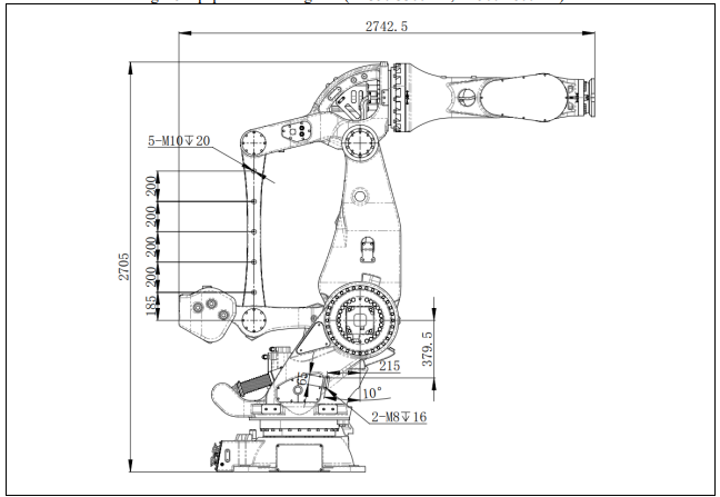
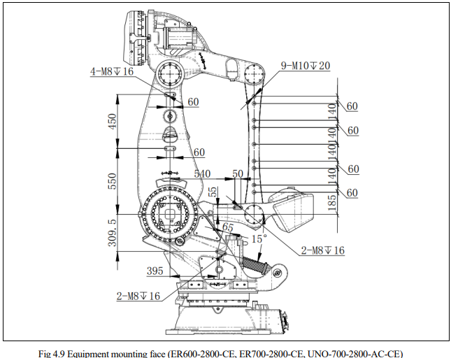
4.2.EQUIPMENT MOUNTING FACE
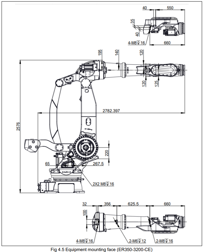
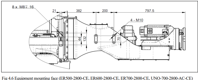
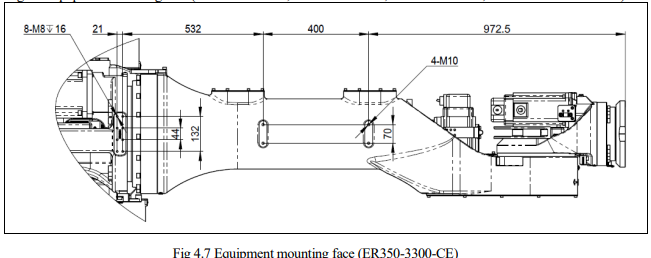
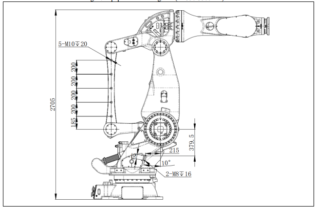
As shown in the figures below, tapped holes are provided to install equipment to the robot.
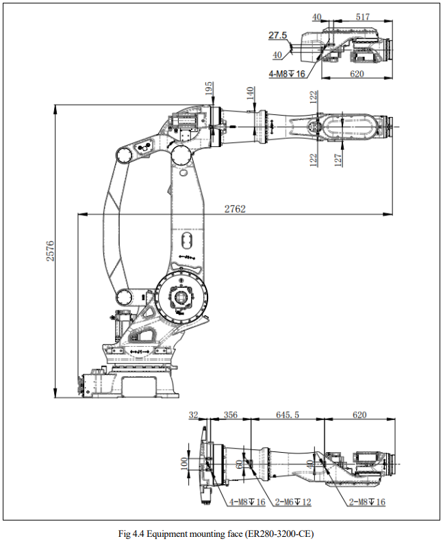

4.3.PIPES AND TUBES
The robot has inlets and outlets openings to supply air or hydraulic pressure to the end effector.
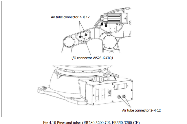
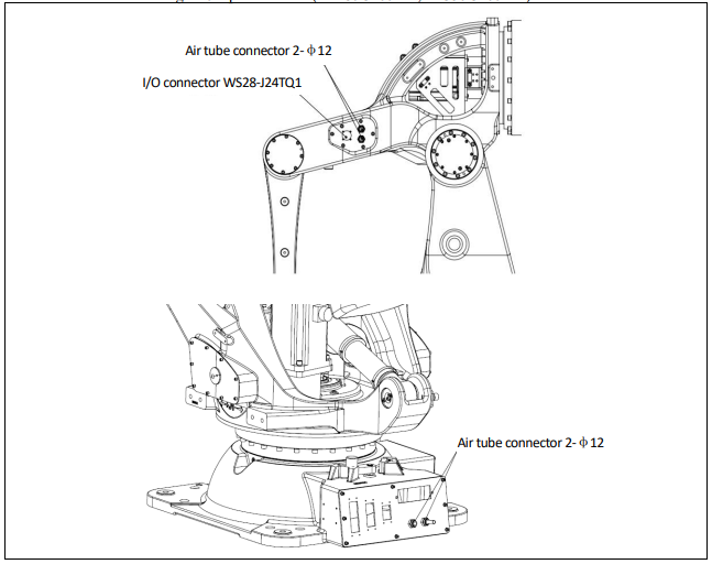
Fig 4.2 Pipes and tubes (ER350-3300-CE, ER500-2800-CE, ER600-2800-CE, ER700-2800-CE,
UNO-700-2800-AC-CE)
No comments to display
No comments to display