
5. CHECK AND MAINTENANCE
Before performing any maintenance, be sure to read SAFETY PRECAUTIONS and understand the content.

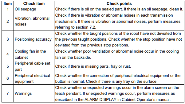
5.1. DAILY CHECKS
Check the items below before daily operation as occasion demands
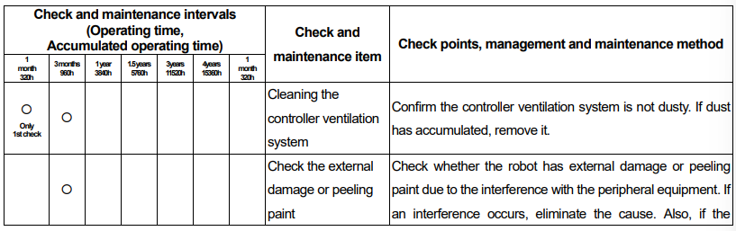
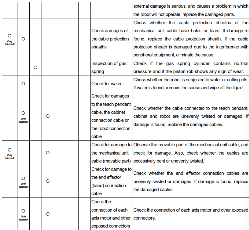
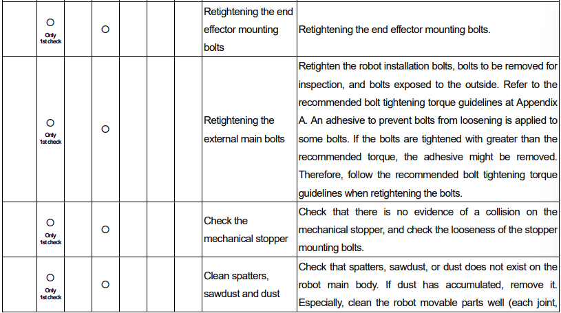
5.2. PERIODIC CHECKS AND MAINTENANCE
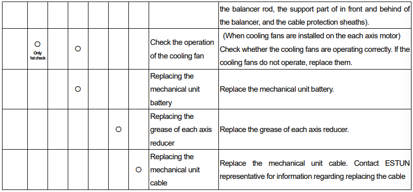
Check the items at the intervals recommended below based on the total time or the accumulated operating time, whichever comes first. Periodic checks keep the performance of the robot. The items below can be performed by yourself, or you can contact ESTUN for maintenance service.
5.2.1.Inspection of gas spring

There are two methods to check the gas spring.
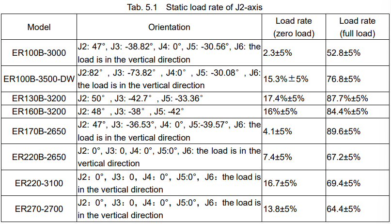
Method I: check the gas pressure of the spring by measure the static load rate of J2-axismotor.
Method II: check with a gas-pressure meter.
This robot needs a gas-pressure meter (model GA3500) to check the gas spring.

Procedures of checking the gas spring pressure.
a) Adjust J2-axis to 0° and then turn off the power supply.
b) Remove the cover and screw of the gas spring inlet.
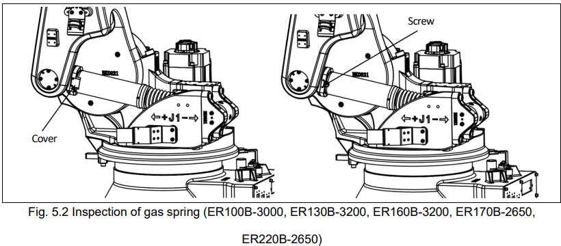
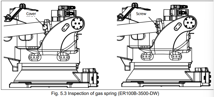
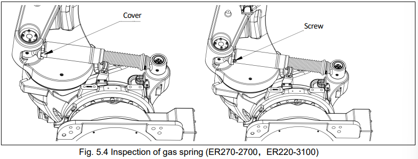
c) A gas pressure detection device is mounted at the air inlet and specified pressure is listed in the table below;
d) After confirming the air pressure, remove the detection device and reinstall the screw and cover.
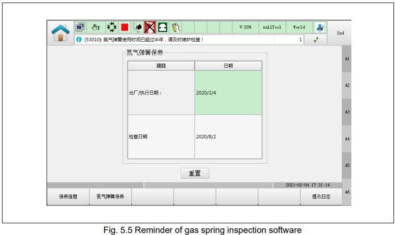
Method III: Using the software reminder function on the teach pendant.

Tab. 5.3 Gas-pressure corresponding to the surface temperature of the gas spring (ER160B-3200,
ER220B-2650)




5.3. ADJUSTING THE BELT
J5-axis of this series of robot is drove by timing belt. After a period of operation, the belt tense will reduce. This section describes how to strain the J5-axis timing belt.

Procedures of straining J5-axis timing belt is shown as below.
1.Disassemble the hexagon flat round head screw M6X16 under the cover on the right side of the small arm, and keep it in a proper place.
2.Unscrew the hexagon screw M8X30 on the mounting plate of J5-axis.
3.Adjust the device underneath the mounting plate, mainly adjust the M6 nut, to make the screw firmly against to the mounting plate of J5-axis motor.
4.Test the tense on the side of the timing belt. Refer to the table below for a proper tense value.
5.Tighten the hexagon screw M6X16 on the mounting plate to fix the plate.
6.Use hexagon flat round head screw to fix the cover to the right side of the small arm. Tighten the screw.
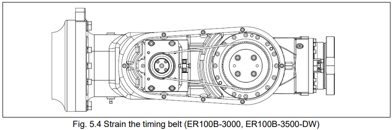
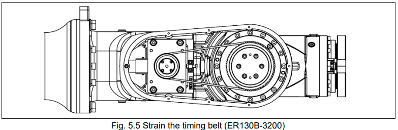
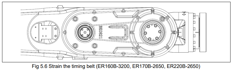
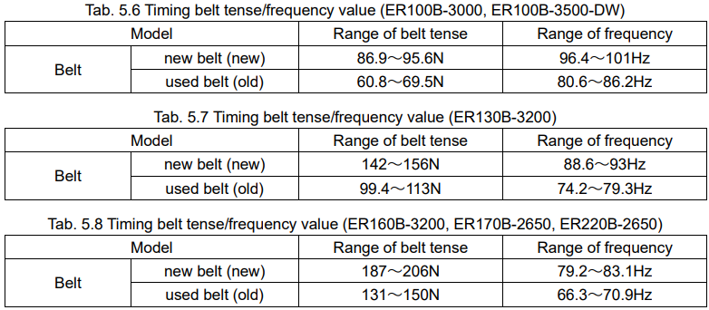
When measuring, it is best to measure the frequency (Hz) to determine the timing belt tension.
Measure the belt tense according to frequency, as internal parameter set is not required.
5.4. REPLACING THE BATTERY
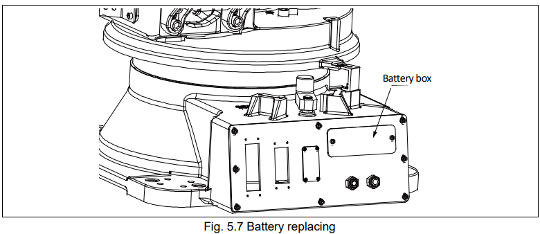
The position data of each axis is preserved by the backup batteries.
The batteries need to be replaced every one year. Also use the following steps to replace the batteries when voltage drop alarm occurs.
Procedures of replacing the battery:
1. Press the emergency stop button to avoid any dangerous situation.
2. Remove the cover of the battery box.
3. Take out the old battery from the box.
4. Fix the new battery into the battery box. Make sure the direction is correct.
5. Fix the cover of the battery box.

5.5. GREASING
Greasing is required to each part every 3 years, or for a cumulative operation time of 11520 hours, whichever occurs first, according to the following steps. Refer to the table below for the brand and quantities of the grease applied to each joint.


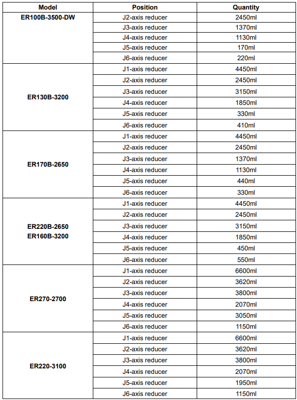
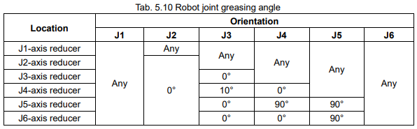
The table below lists the recommended azimuth for grease replacement or replenishment operations.
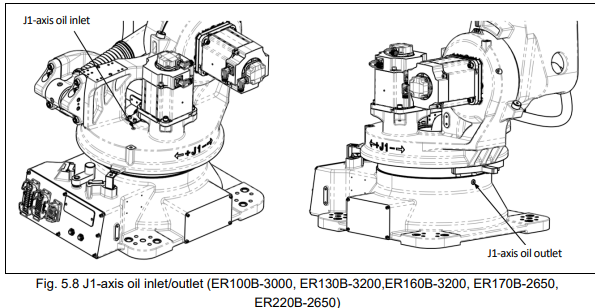
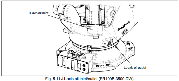
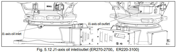
5.5.1.Position of oil inlet/outlet on each axis

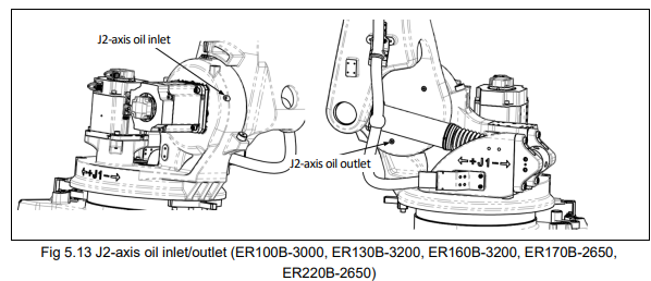
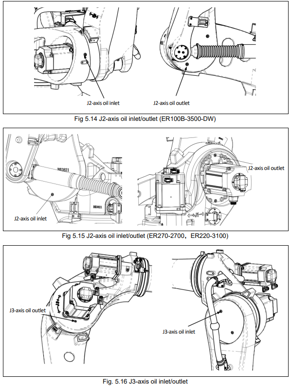
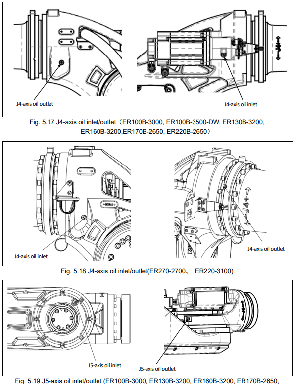
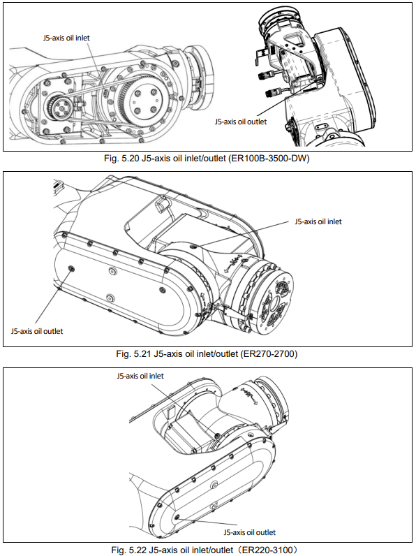
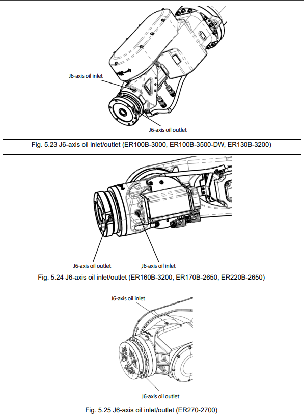
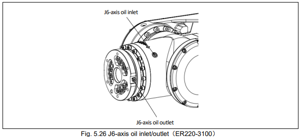
5.5.2.Procedures of greasing
The following steps only applied to operation of reducers of J1, J2, J3, and J4 axes.
a) Teach each joint to run at a speed of 100% for 10-20min, to make the grease into oil with low viscosity.
b) Move the robot to the gesture of greasing, then turn off the power supply.
c) Put an oil recycle container beneath the grease outlet.
d) Remove the screw on the inlet and outlet of each joint.
e) Inject new grease via the oil inlet until new grease goes out of the outlet. The amount of oil injected should be equal to the amount that is discharged (including those discharged after warming up the machine).
f) Release the residual pressure in the grease groove according to section 5.5.3.
g) Install the screw to oil inlet and outlet with a torque of 13.7N·m.
If greasing is not performed properly, the internal pressure inside the grease bath may increase suddenly, which will damage the seal part, resulting in oil leakage and abnormal operation. Therefore, when performing greasing, observe the following precautions.
Open the grease bath vent (remove the screw on the oil outlet) before greasing.
Inject the grease/oil slowly without excessive force.
Avoid compressed gas pump (powered by factory gas source) whenever possible.
Use specified model of grease/oil. Unauthorized model of grease may cause damage to the reducer or other problems.
When greasing is completed, make sure that there is no oil/grease leakage outside the outlet. and the grease bath is not pressurized. Then close the outlet.
Clean the excess oil/grease on the floor to avoid accidents such as slipping or fire.
5.5.3.Procedure for releasing remaining pressure within the grease bath
Release remaining pressure with the following procedures. Attach bags under the oil outlet to prevent spilled oil/grease from splattering.
a) Power the robot, and operate at a 100% speed with full load for 4 hours continuously.
b) Stop the running program of the robot at zero position, turn off the servo power with the teach pendant.
c) Disassemble the screw at oil inlet of each axis after safety confirmation. Do not face the screw when removing it, in case that oil with high pressure and high temperature ejects, resulting personnel injury.
d) Retighten the screw 3% seconds later after removing it, and clean up the oil around the screw with a clean cloth.
e) Be sure to complete pressure releasing of a robot (step c and step d) in 15 minutes. Otherwise, it should be repeated from step 1.
No comments to display
No comments to display