
6. Project Operation
After creating a project, you can run the project for measurement or detection. By default, the running page of a project shows after login.
6.1 Create a Project
Perform the following steps to create a project:
1. Set Parameters for Cameras: Set cameras' parameters related to triggering mode and image display. See Set Parameters for Cameras for details.
2. Configure Base Image: A base image provides a reference for the measurement. You can select the image acquired currently or a historical image, or import an image from the PC. You can enable the Position Correction function so that the Software can perform the measurement based on the base image even if the measured object is not put rightly. See Configure Base Image for details.
3. Configure Tools: For objects with different features, you can select different features and measuring tools for the project. See Configure Tools for details.
4. Output Settings: Set the related parameters for project output, including measuring results, image saving, results output, I/O settings, etc. See Output Settings for details
6.1.1 Set Parameters for Cameras
Set trigger method and adjust image parameters such as brightness, mechanical focus, light source, image color, etc.
Trigger Settings
Set parameters including trigger mode, trigger source, trigger cache, trigger delay, etc.
● Trigger Mode: you can select Off or On as the trigger mode. If you select Off, the camera will acquire images continuously and the Software will output images automatically; if you select On, the camera will acquire images according to the signal sent by the trigger source.
● Continuous Running Interval: Available when you select Off as the trigger mode. It refers to the time interval between each trigger.
● Trigger Source: You can select Trigger IO, Button, Software, or Communication.
○ Button: Press the button among the indicators on the top of the camera to trigger an
acquisition.
○ Software Trigger: The Software sends a command of acquisition to the camera.
○ Communication Trigger: Send specific strings by a communication tool (except FTP tool) to the camera to trigger an acquisition. If you select this as the trigger source, you need to add related communication tool to the project.
○ I/O Trigger: The camera acquires an image when receiving the IO signal of which the IO type is set as Trigger. You can click IO Setting
○ under the Trigger Source to open the IO Settings window to set the I/O related
parameters. See IO Settings for details.
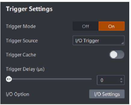
Figure 6-1 Trigger Settings
● Software Trigger: Available when you select Software as the trigger mode. You can click Execute to command the camera to acquire images.
● Trigger Cache: If you do not enable this, when the camera is dealing with the triggering signal of acquisition, the newly-sent signals will not be received by the camera; if you enable this, 3 newly-sent triggering signals will be saved when the camera is dealing with the triggering signal of acquisition, and the camera will deal with the newly-sent triggering signals after dealing with the last signal.
● Trigger Delay (μs): The delayed duration before the camera deals with the received triggering signal.
● Filter Time (μs): Available when the Trigger Source is Button. If the duration for pressing the triggering button is shorter than the Filter Time duration, the trigger will fail. This function helps to avoid fault triggers resulted by mistake press on the button.
● Communication String: Available when the Trigger Source is Communication. When the communication tool sends the same communication string to the camera as the string you enter here, the camera will be triggered to acquire an image.
One Key Settings
SC3000 series camera supports one-key settings, while SC2000E series camera does not support one-key settings.
Click Auto Adjustment to adjust the brightness, white balance, focus, and other parameters
automatically. The camera will adjust to the optimum settings according to the actual
environment.
Note
● Auto adjustment might take a while. You cannot operate the Software during auto adjustment.
● Only colored camera has the white balance feature
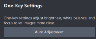
Figure 6-2 One-Key Settings
Brightness Settings
Set the brightness of pictures acquired by the camera. You can adjust the image brightness manually or let the Software adjust image brightness automatically.
● Set the Brightness Manually: Adjust the Exposure Time and Gain manually to change the image brightness.
● Auto Adjustment: After setting the Brightness Standard, click Auto Adjustment to let the Software adjust the image brightness automatically.
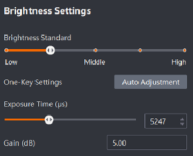
Figure 6-3 Brightness Settings
Mechanical Focus
You can adjust the focal length of the camera.
● Focus Step: Set the stepping value of focal length adjustment.
● Focus Position: Adjust the focus position of the camera.
● Global Focus: Click Global Focus to let the camera find the optimum focal length.
● Regional Focus: Click Regional Focus and then draw an ROI on the right. The Software will focus in the ROI.
● Restore Default: Click Restore Default to restore the focal length to its default value.
● For users of SC2000E and SC2000E(mini) series camera, you need to focus manually on the camera.
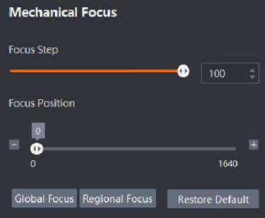
Figure 6-4 Mechanical Focus
Light Source Adjustment
With this function, you can select the used light source on the camera.
● For SC2000E and SC2000E(mini) series camera:
Click the aiming light or light source to enable them. the four sources together. When enabling the light sources, the four light sources will be enabled at a time.
● Duration: The duration for which the light source flashes.
Make the light source light in advance or later than the configured time by adjusting
Light Source Adjustment.
Note
The values of Duration and the Light Source Adjustment impact each other. For example, if you set the Duration as 3800 us, you can only light the light source in advance, which means the maximum value of Light Source Adjustment can only be 0. The detailed values are subject to actual operations
For other series of cameras:
Select a light source control mode in the Light Source Control field.
Custom: In this mode, you can select the light source to be enabled according to your needs and set related parameters. All: All the light sources will be enabled, and you can set the related parameters for all light sources at a time. None: No light source will be enabled and you do not need to set related parameters.
If you select Custom as the Light Source Control mode, select the light sources on the light source image to enable them.
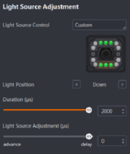 Figure 6-5 Light Source Adjustment
Note
● If you select Custom as the Light Source Control mode, you need to select light sources and set parameters for them.
● If you select All as the Light Source Control mode, the parameters can be set uniformly
Other Parameters
Set parameters including frame rate, Gamma, image size, mirror image, greyscale image
output, etc.
● Frame Rate: Set the frame rate of real-time acquisition. The maximum frame rate is the maximum frame rate of the camera itself.
● Gamma: Gamma is a non-linear mechanism of mapping. When the value is between 0.5 and 1, the dark area of the image will become more bright; if the value is between 1 and 4, the dark area of the image will become less bright.
● Image Size Setting: Draw ROI of image resolution. If you select Original, the whole image will be displayed with the resolution. If you select Custom, you can click Edit and adjust the image size on the Live View window and click Finish. Or you can edit the value in Image Width and Image Height to adjust the image size.
Note
The setting of this parameter requires device support.
● Mirror Image: After enabling this, the image will be displayed like the right side of the original image appears on the left and the left side appears on the right.
Note
The setting of this parameter requires device support.
● Greyscale Image Output: The parameter for colored cameras. If you enable this, images will be output in Mono 8 format.
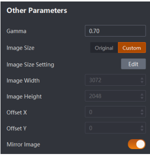
Figure 6-6 Other Parameters
Note
If you have enabled Greyscale Image Output for a colored camera, the Color Image Parameters will be hidden, and the tools for area of certain color and color contrast will be unavailable.
Color Image Parameters
Color Image Parameters are parameters for colored cameras exclusively, including white balance and CCM. It is available only when the Greyscale Image Output is disabled. White Balance: It corrects colors in different lighting condition. It keeps white area white all the time by adjusting R, G, and B value of the image. The supposed proportion of R, G, and B is 1:1:1. you can configure white balance manually or automatically.
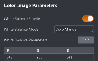
Figure 6-7 Color Image Parameters
Awb Once: After enabling the White Balance Enable, the White Balance Mode is in automatic mode. In this situation, the camera adjusts the R, G, and B value according to the real-time image color automatically.Awb Manual: Click Edit beside the White Balance Mode. Edit the R, G, and B value and click Edit to finish.
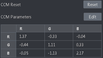
After processed by white balance, the image may be darker than before, and some color may vary from the standard value. In this situation, you can correct the image color by CCM to make the color more bright.
● CCM Reset: Click Reset and the camera will adjust the CCM values automatically.
● Edit CCM Parameters: Click Edit to edit the values in the following table. Click Edit again to finish.
6.1.2 Configure Base Image
After setting parameters for the camera, you need to set a base image for the camera for position fixture. It is a required step for position fixture and tool test. Position fixture helps locating objects when the object positions or angles change. So that the detection area will change according to the base image to avoid acquisition failure caused by the change of object position or angle. The results of enabling and disabling Fixture are shown as the following. It is recommended that you enable this function.
Before You Start
Make sure you have set parameters for the camera
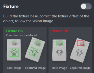
Figure 6-9 Position Fixture
Steps
1. Get a base image via the window on the right. You can get a base image by 3 ways.
● Current Image: Click Current Image to get the image displayed on the right as the base image.
● Historical Image: Click Historical Image to select an image stored in the camera as the base image. You can search wanted images by setting the filtering conditions.
Note
○ The SC2000E and SC2000E(mini) series devices cannot store images in the camera, and thus they do not support importing historical images from the camera.
○ For the image search during importing historical image(s), see Acquired Image Management for details.
● Import: Click Import to upload an image in the PC to the Software as the base image.
Note
Only images in JPG, BMP, and PNG format are supported.
2. Switch on  on the right of Fixture to enable Fixture.
3. Click Edit on the right of Template Area and select  or
or  , and then draw on the live view window.
Note
● After drawing an area, you can click  → Select similar patterns to manually set the
match point. Click Reset to restore to default if needed.
● Refer to How to draw an ROI? for ROI drawing details.
4. Click Edit to finish drawing the template.
5. Optional: If you need to shield an area in the template area, perform the same operation in the last step after clicking Edit on the right of the Template Shield Area.
6. Select the configuring mode for Template Sensitivity.
● Auto: Set the sensitivity by setting the degree. The higher the sensitivity, the better the fixture quality. Noises may be recognized as the template if the sensitivity is too high, so it is recommended that you set the sensitivity according to your actual need.
● Manual: Set the sensitivity by setting the Coarse Granularity and the Greyscale Threshold.
7. Optional: Configure the Extend Parameter
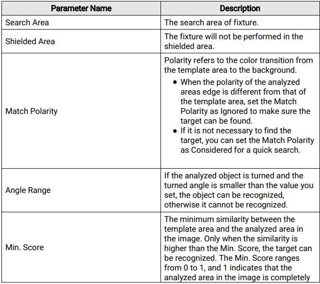
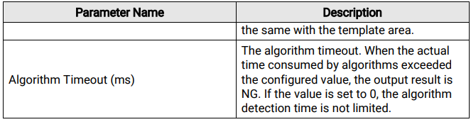
8. Click  Test Run beside Fixture to test the fixture effect.
Note
Click  to end the test.
6.1.3 Configure Tools
Add tools for the project according to your actual need.
Before You Start
Make sure you have set parameters for the camera and have set the base image.
Steps
Note
The camera may supports multiple types of tools. The supported tool types of different camera models vary. See the camera datasheets for details about supported tool types.
1. Click  on the top left to open the window for adding tools.
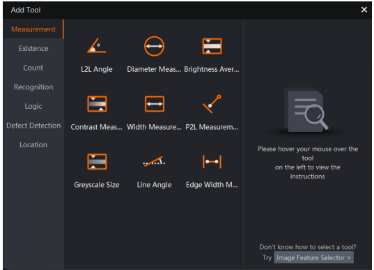
Figure 6-10 Window for Adding Tools
2. Select a category on the left and double-click a tool to enter the configuration page of the tool. Here we take Spot Count tool as an example.
Note
You can click Image Feature Selector to select the tools according to tool features. But some tools may not show.
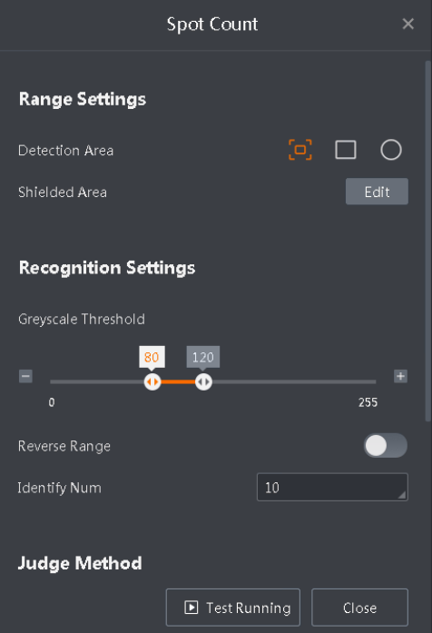
Figure 6-11 Spot Count Configuration Page
3. On the base image displayed on the right, configure the related parameters according to your actual need.
Note
● For different tools, the parameters vary. See Tool Introduction for details about different tools.
● Generally, it is not necessary to set the Extend Parameters unless you cannot get your wanted analyzing result.
4. Optional: Click Test Running to test.
5. Click Close to quit the page for setting parameters and go to the Tool Configuration page.
Note
Green indicates that the analyzing result is OK, while red indicates that the analyzing
result is NG. You can click  to edit a tool.
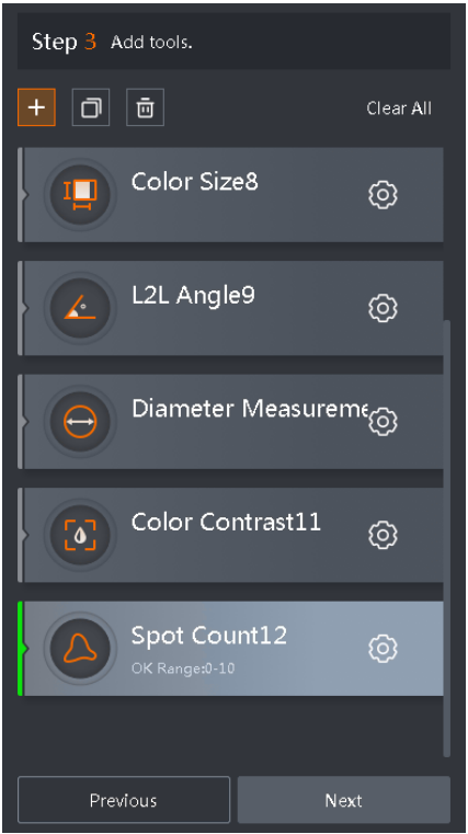
Figure 6-12 Tool Configuration Page
6. Optional: Select a tool and click  to duplicate the tool and the duplicated tool will be displayed at the bottom of the tool list.
7. Optional: Select a tool and click  to remove the tool.
8. Optional: Click Clear All to remove all the tools in the list.
9. Optional: Click the name of a tool to edit its settings.
6.1.4 Output Settings
You can configure the parameters for the results of project running, image saving, result output, and I/O settings
Note
● Make sure you have set parameters and base image for the camera, and have selected tools for the project.
● The SC2000 E series devices cannot store images in the camera.
Project Results
You can set the rules for outputting the results of a project running.
1. You can select the project results.
All Tool OK
The results output by all the tools are OK.
Any Tool OK
The result output by any tool is OK.
Custom
Customize the logic of result output.
If you select Custom as the Project Results, you need to click Edit below to customize the running logic.
2. On the Custom Logic page, you are required to configure the Logic Type and Logic Data. When the logic data meets the standard of the logic type, the result will be OK, or the result will be NG.
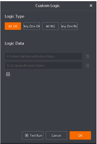
Figure 6-13 Custom Logic
Logic Type
You can select All OK, Any One OK, All NG, or Any One NG.
Logic Data
Click  to subscribe the status of each module as the logic data of the project.
3. Click Test Run to test the data, and the result will be displayed on the lower left of this
panel and the image on the right.
Note
The Test Run button functions the same as that in the I/O part
Scheduled Output
You can enable the scheduled output and configure the output schedule of partial results.
Note
Now only the outputs of communication settings (except FTP) and I/O information of SC5000 series and SC7000 series cameras are supported.
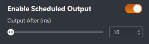
Figure 6-14 Enable Scheduled Output
Make sure you have switched on the device's trigger mode. You can configure the output time (Output After) as needed after enabling the scheduled output.
When the device receives a trigger signal, it will take the signal generation time as the start point and output corresponding results after the configured time period.
● If the project running is completed within the configured time period, the communication module will output the result string (such as OK or NG), and the I/O module will execute the action corresponding to the result.
● If the project running is not completed within the configured time period, the communication module will output NG, and the I/O module will execute the action corresponding to the NG condition.
Save Image
With this function, you can save images in the camera.
Note
This function should be supported by the cameras.
After enabling Save Image, click Edit to configure the related parameters.
Image Saving
The rule for saving images.
Output Condition
Subscribe to the information such as module status of different tools as the reference for saving images.
Image Saving Strategy
You can select Not Save Image, Save Image (OK), Save Image (NG), and Save All.
Saving Format
The format of saved images, supporting BMP and JPG.
Storage Method
The rule for saving newly received images when there is no more space on the camera for saving images. You can select Stop Saving Image or Overwrite. Stop Saving Image indicates newly received images will not be saved, while Overwrite indicates the oldest images in the camera will be overwritten by the newly received images.
Image Naming Rule
The rule for naming the saved images.
Frame No.
If you enable this, the frame No. of the image will be contained in the image name.
Result
If you enable this, the running result of the Output Condition will be contained in the image name.
Start Tag and End Tag
The start character and the end character in the name of the saved images. You can customize it. Only letters, digits, and characters including !, @, #, ^, &, (, ), -, _, =, +, ., ,, ;, ` are allowed.
Delimiter
The separator between each option. You can customize it. Only letters, digits, and characters including !, @, #, ^, &, (, ), -, _, =, +, ., ,, ;, ` are allowed.
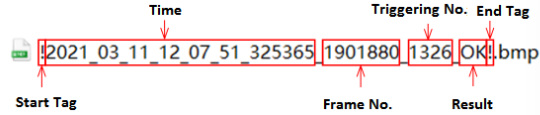
Figure 6-15 Image Naming Rule
Note
By default, the time and triggering time will be contained in the image name.
Tool Results
With this function, the Software can output a result after processing the data of each module and strings.
1. After enabling Tool Results, click Edit to add data.
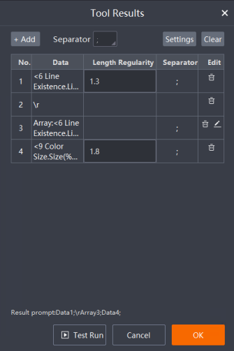
Figure 6-16 Tool Results
2. Click Add to add data, symbol, or array as the output data.
Data
Subscribe to related data of different modules of the project as the output result.
Symbol
Add symbols to the output data.
Array
Combine multiple pieces of data as the output result.
Length Regularity
Set the length and regularity of the output data. The digits before the decimal point indicates the length of the output data, and the digits after the decimal point indicates the regularity of the output data (i.e., how many decimal places the data should be accurate to).
Note
● If the length of the output data is smaller than the set length, the vacant digital places will be zero. For example, the length regularity is 4, and the actual result data is 1, the output data will be 0001.
● Length and regularity range of integer data: [0-10].
● Length and regularity range of float data: [0-10][.][0-10].
Separator
A separator separates different data. When the added data is a symbol, there will be no delimiter following it. You can select a comma or a semicolon as a delimiter, or customize it.
Note
Data outputs only one piece of data, while Array outputs a group of data in order.
3. After adding data, you can perform the following operations.
● Select a piece of data and click  to delete it. You can click
  to edit an array.
● Click Clear on the top right to delete the configured data. The output content will be displayed in Result prompt on the lower left.
● Click Settings to configure the failure prompt, and set the condition for outputting the results you configured.
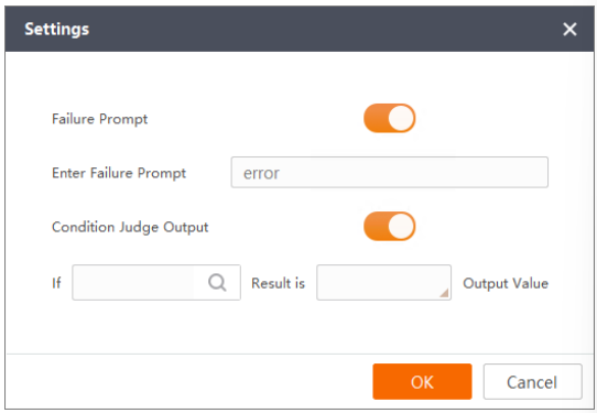
Figure 6-17 Settings
Failure Prompt
A window will pop up when a failure occurs.
Enter Failure Prompt
The information given in the pop-up window.
Condition Judge Output
When enabled, select a specific module and its corresponding status (OK or NG). The results will only be outputted when the condition configured here is met. When disabled, all configured results will be outputted.
4. Click Test Run to test the data, and the result will be displayed on the lower left of this
panel and the image on the right.
I/O
If the result is qualified, the camera can send signals to connected devices.
1. After enabling I/O, click Edit to set related parameters.
On the IO Output panel, the IO signals whose IO types are set as Output will be loaded
and displayed. You can enable an IO signal according to your need and set the related
parameters.
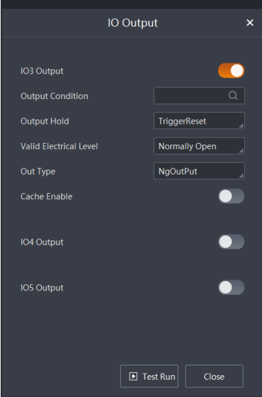
Figure 6-18 I/O Output
Output Condition
You can subscribe to the module status of different tools as the reference for IO output.
Output Hold
You can set the IO signals and keep the electrical level status.
Disable
Control the IO signals output by configuring Duration and Delayed Duration.
TriggerReset
When the device receives a trigger signal, it sets the output signal to a low electrical level, and then sets the output signal to the corresponding electrical level according to the subscribed module result and Out Type. The electrical status keeps to the next trigger signal.
ReverseReset
Compared with the configured Out Type, when the received module status is opposite, the output signal will be set to a low electrical level before the module status becomes the same.
Note
This parameter is supported by the SC5000 series and SC7000Pro series cameras only.
Duration Time
The duration of outputting signals.
Delayed Time
The camera outputs signals after the Delayed Duration.
Valid Electrical Level
You can select Normally Closed or Normally Open as the valid electrical level. Normally Closed is used for low electrical levels, while Normally Open is used for high electrical levels.
Out Type
The condition for outputting IO signals. If you select ExposureOutPut, the camera outputs signals when it starts exposure, instead of being controlled by the Output Condition you set before. If you select NgOutPut or OkOutPut, the camera outputs signals when the subscribed condition is triggered.
Note
The ExposureOutPut is not supported by the SC2000E series cameras.
Cache Enable
If you enable this, when the camera receives a new signal when outputting signals, the newly received signal will be saved temporarily and the camera will output them after finishing the last output.
Note
This parameter varies according to different series cameras.
● It is not supported by the SC2000E series cameras.
● For SC3000 series cameras, up to 3 signals can be saved.
● For SC5000 and SC7000Pro series cameras, up to 16 signals can be saved.
2. Click Test Run to test the data, and the result will be displayed on the image on the right.
6.2 Run Project
After logging in to the Software or loading a project, you can manage the project and set its running mode on the following page.
In the upper-left area, you can manage the project, see Menu Bar for more details; in the lower-left area, you can see the tools added to the project, see Tool List for more details; in the right area, you can select the display mode as "Camera Mode" or "Image Mode", and view the detection result, see Live View Panel for more details.
No comments to display
No comments to display