
11. Safety
11.1 Introduction to this chapter
This chapter mainly introduces the settings of xCore safety related functions.
11.2 Safety password
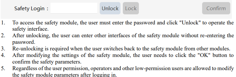
A password is required to unlock the safety module, and it is "safety" by default.
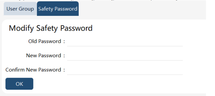
The safety password can be changed through Settings —> User Group —> Safety Password.
11.3 Joint limit
11.3.1 Highlights
The joint limit monitors the parameters of robot joints. When the joint exceeds the threshold, the robot will immediately stop running, and the RSC robot will enter a safe stop state. The joint limit mainly includes joint position limit, joint velocity limit, joint torque limit, and joint power limit. Each limit can be configured with two parameters for users to determine the threshold based on the current mode (normal mode or reduced mode). The user has the flexibility to enable or disable specific functionalities as required.
11.3.2 Joint position
11.3.2.1 Highlights
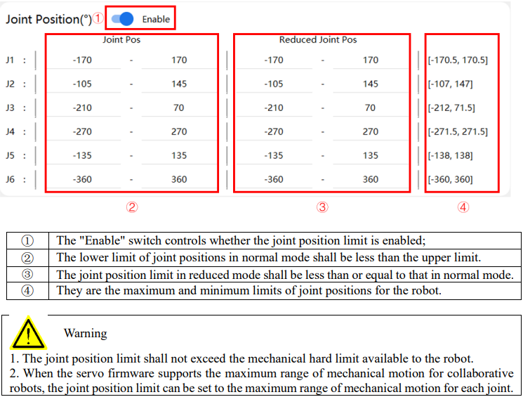
The joint position limit is used to set the maximum motion range of each joint at the software level to avoid interference or collision between the robot and peripheral equipment. During the drag process, the joint angles are also protected by the joint position limit. Drag near the joint position limit will give the manipulator a rebound force against the direction of the joint position limit. The range of the drag rebound force is within 10° of the upper and lower joint position limits set by the HMI interface. Assuming that the joint 1 position limit is −170° to 170°, then the range of the drag rebound force is [−170° to −160°] and [160° to 170°].
11.3.2.2 Handling for moving beyond the joint position limit
In some rare cases, the robot may move beyond the joint position limit, such as triggering an emergency stop when moving to the limit, and exceeding the joint position limit when executing STOP 0. In xCore V2.1 and earlier versions, when the robot has one or more joints outside the joint position limit, it will be unable to jog or run programs. At this point, it is necessary to first cancel the joint position limit, then jog the out-of-limit joint back within the joint position limit, and finally enable the joint position limit again.
In xCore V2.2 and later versions, for non-RSC robots, when the robot moves beyond the joint position limit, it is allowed to jog the robot back within the joint position limit. For RSC robots, when the robot moves beyond the joint position limit, it will enter the safe stop state. At this point, it is necessary to first cancel the joint position limit, then click "emergency reset", jog the out-of-limit joint back within the joint position limit, and finally enable the joint position limit again.

11.3.3 Joint speed
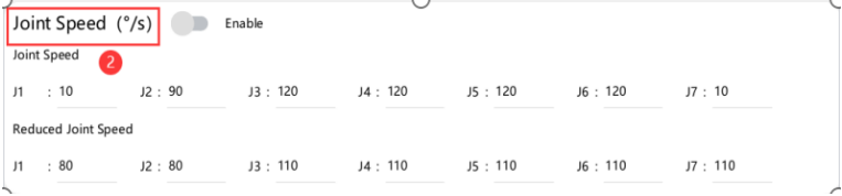
Joint speed limit: The joint speed limit can be turned on/off by an enable switch. When it is enabled, the angular speed of robot joints will be monitored in real time. Different monitoring thresholds will be used based on the current mode (normal mode or reduced mode). If any joint angular speed exceeds the threshold, the robot will immediately plan to stop and power off, and the RSC robot will enter a safe stop state.
11.3.4 Joint torque
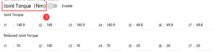
Joint torque limit: The joint torque limit can be turned on/off by an enable switch. When it is enabled, the torque of robot joints will be monitored in real time. Depending on the current mode (normal mode or reduced mode), different monitoring parameters are used to determine the threshold. If any joint torque exceeds the threshold, the robot will immediately plan to stop and power off, and the RSC robot will enter a safe stop state.
11.3.5 Joint power
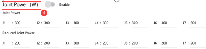
Joint power limit: The joint power limit can be turned on/off by an enable switch. When it is enabled, the power of robot joints will be monitored in real time. Depending on the current mode (normal mode or reduced mode), different monitoring parameters are used to determine the threshold. If any joint power exceeds the threshold, the robot will immediately plan to stop and power off; and the RSC robot will enter a safe stop state.
11.4 Robot limits
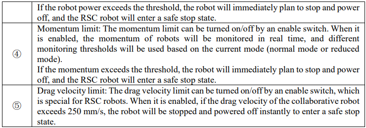
11.5 Virtual wall
11.5.1 Highlights
The virtual wall is specifically designed to confine the working area at the end of the flange in the Cartesian space (translation only) drag scene of the xMate collaborative robot. As users approach this virtual barrier, they will encounter a reactive force exerted by it.
The typical usage scenario involves medical professionals utilizing xMate collaborative robots as auxiliary tools for surgical operations through dragging actions. In order to enhance safety and prevent any potential misoperations, establishing a virtual wall becomes crucial to restrict the operational space of the robot's flange.
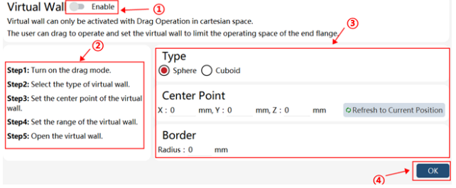
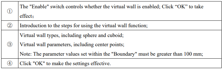
Note: In the extreme case of excessive drag force and speed, the robot may exceed the range of the virtual wall, and the system will provide corresponding prompts.
11.6 Collision detection
11.6.1 Highlights
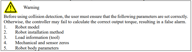
Collision detection is a passive function that relies on the estimation of the robot's dynamic model. It enables timely identification of unexpected collisions with the external environment during robot operation, allowing for prompt implementation of pre-set measures to mitigate any potential damage.
11.6.1.1 Setting mode
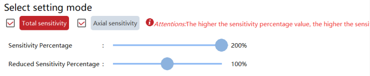
The "whole setting" and "single joint setting" are available, and at least one of them shall be checked. According to different setting modes, the sensitivity of the whole robot or single joint can be adjusted. The higher the percentage, the higher the sensitivity, and the easier it is for the robot to detect collisions. The factory default sensitivity is set to 100%, which can be adjusted by the user according to their needs. Different sensitivity thresholds will be used based on the current mode (normal mode or reduced mode).
11.6.1.2 Impact limit
Impact limit (including TCP impact and elbow impact): The impact limit can be turned on/off by an enable switch (collision detection is also turned on). When it is enabled, the TCP impact and elbow impact of the robot will be monitored in real time. Depending on the current mode (normal mode or reduced mode), different monitoring parameters are used to determine the threshold.
When any monitored value exceeds the threshold, the robot will enable the trigger behavior of collision detection, and the RSC robot will enter a safe stop state.

11.6.1.3 Trigger behavior
The trigger behavior only includes a soft stop.
Soft stop: a collision detection stop method for robots and high stiffness environments. The greater the soft, the faster the response of the robot, and the greater the load of the robot joint; soft generally uses the default 0. After a safe stop, the robot will automatically power off. In this state, the robot supports direct power-on and continues to run the program along the current path.
11.6.1.4 Driving torque limit
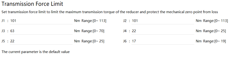
The driving torque limit is used to limit the maximum driving torque of the reducer and protect the important parts of the driving chain and the mechanical zero.
The driving torque limit is available for collision protection*. When the controller detects that the driving torque exceeds the limit, the robot will trigger an error message indicating that the driving torque exceeds the limit. For the first start, the robot will use the default driving torque limit.
11.6.1.5 Parameter identification
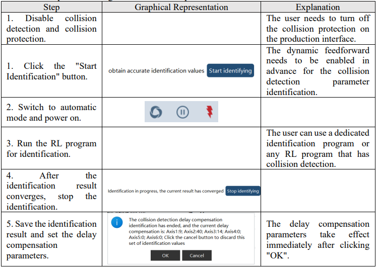
Collision detection parameter identification is used to identify and set the internal parameters of the collision detection algorithm to improve the accuracy of impact monitoring, reduce the probability of false alarms, and optimize collision detection performance.
Collision detection parameter identification supports "delay compensation parameter" identification and setting.

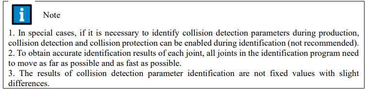
The detailed steps for enabling collision detection parameter identification are as follows:
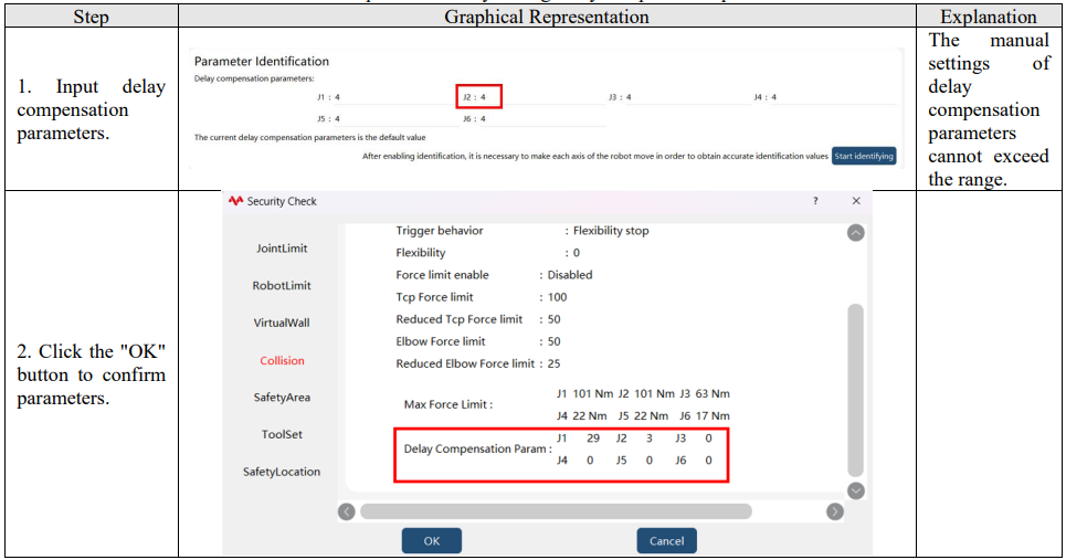
The detailed steps for manually setting delay compensation parameters are as follows:
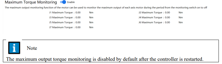
11.6.1.6 Maximum output torque monitoring
The maximum output monitoring is used to monitor the maximum output torque of the motor of each joint during the period from enabling to disabling. Users can adjust the driving torque limit of each joint according to the maximum output torque monitoring parameters.
11.6.2 Notes
1. During program execution, if the robot collides with external devices while moving at high speed and the collision force exceeds a certain threshold, triggering an alarm and stopping the servo driver, the robot can only resume operation after clearing the collision, restarting itself, and resetting the servo alarm.
2. Incorrect sensitivity mode selected may cause a false collision alarm. Please select different sensitivity thresholds for each application scenario.
3. The collision detection sensitivity is affected by the robot hardware, and there are differences in sensitivity thresholds between different robots. Currently, the three sensitivity modes only provide a set of nominal values. The user with higher requirements for collision detection sensitivity can fine-tune the sensitivity of each axis based on specific application scenarios through the single-axis setting or adjust the detection sensitivity online through RL commands.
4. After collision detection and safety monitoring are triggered, a pop-up window will appear, and you must click "Confirm" to manually clear the alarm before continuing to run.
5. Collision detection is enabled by default at the factory for collaborative robots.
6. For the description of the collision protection*, see the user manual of the production interface.
11.7 Safe region
11.7.1 Highlights
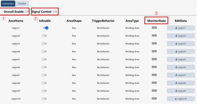
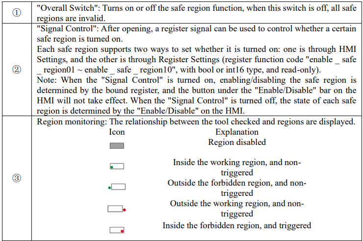
Safe regions are used to set the behavior of the end-effector and elbow in and out of a region. The user can define several safe regions in the space (currently supports up to 10). When the robot enters and exits the safe region, it selectively triggers the preset safety behavior, and automatically modifies the register value (binding the register function code of the safe region).
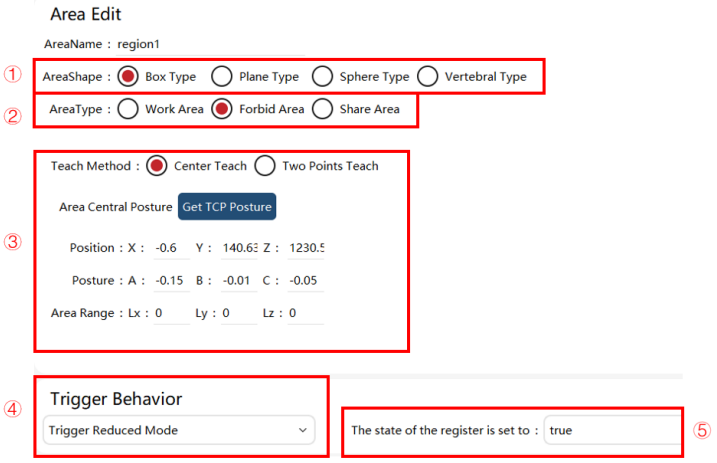
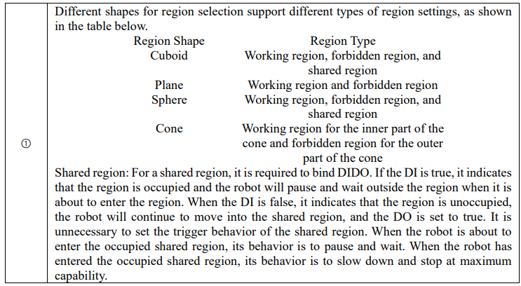
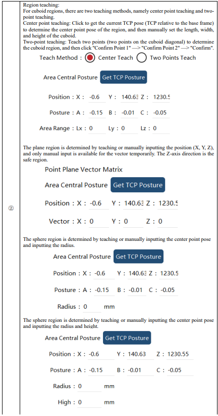
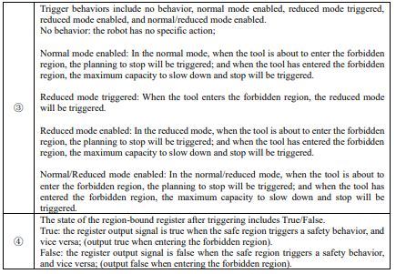
11.7.2 Association of safe region and register
11.7.2.1 Safe region status output
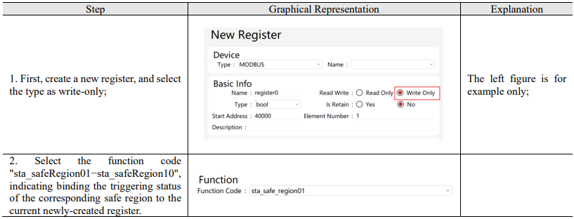
11.7.2.2 Register control safe region enable
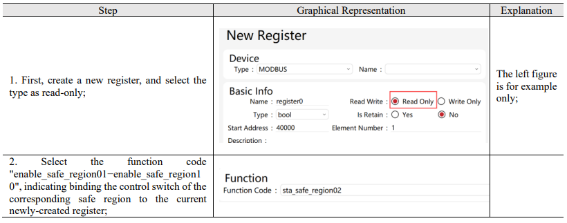
11.8 Tool setting
11.8.1 Tool position
The tool position limit is available to limit the positions of flanges, elbows, real-time tools, and two fixed tools simultaneously. An envelope can be specified for each position. When the envelope of any position exceeds the setting of the safe region, the behavior of the safe region will be triggered (normal mode enabled, reduced mode triggered, etc.).
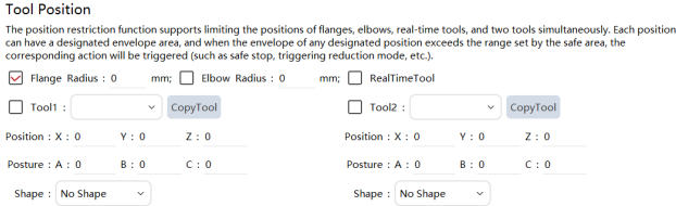
Tool envelope: The tool envelope includes three shapes, namely no envelope, cuboid, and sphere.
Real-time tool: When RL runs motion commands, the real-time tool is the tool in the command. When there is no motion command, the real-time tool is the tool selected on the upper right of the HMI. The envelope of the real-time tool can be set when editing the tool (global tool list in the frame calibration and tool list in the project).
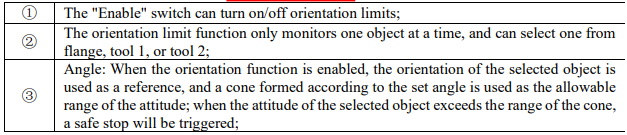
11.8.2 Tool orientation
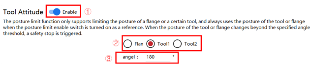
11.9 Safety position
11.9.1 Highlights
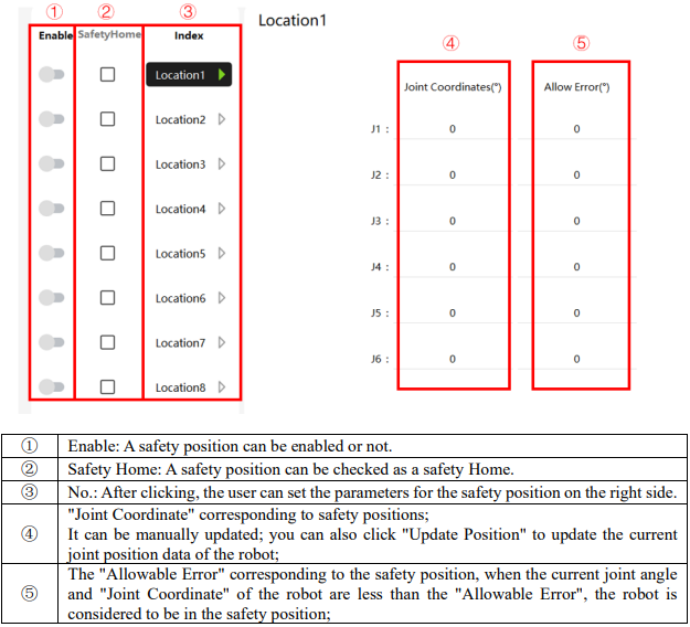
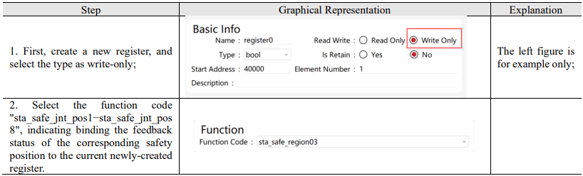
The safety position function refers to the binding register outputting a signal indicating the robot's presence in the predetermined safety position. Through this function, users can ascertain the relative positioning of the robot with respect to the safety position. xCore control system supports up to 8 safety positions with joint angles as reference. Each safety position corresponds to a register function code (type: bool or int16, read/write: write only, sta_safe_jnt_pos1~sta_safe_jnt_pos8). When the current joint angle of the robot and the joint angle set for a safety position are within the allowable error, the value of the register to which the corresponding register function code for the safety position is bound to will be modified automatically (when within the allowable error of the safety position, if the register type is bool, the register value is true; if the register type is int16, the register value is 1). The safety Home is special for RSC robots, and a safety position can be checked as the safety Home. After it is checked, a safety DO signal can be output if each joint of the robot reaches the set range. If none is checked, the safety Home is disabled.
11.9.2 Association of safety position and register
11.10 Safety checksum
To modify the safety settings, click the "OK" button at the lower right of the interface and confirm the settings after the safety checksum.
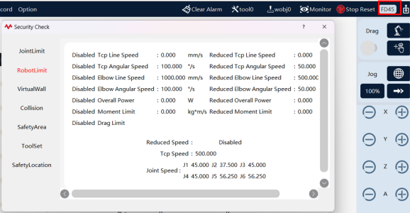
The "Safety Checksum" icon displays a combination of four digits of "number + letter" to allow the user to understand the status of safety-related settings. When there is a change in safety-related settings, it will automatically calculate and generate a new combination of four digits of "number + letter". After clicking the icon, the current safety settings will be available, including the joint limit, robot limit, virtual wall, collision detection, safe region, tool settings, and safety position. After modifying the parameters of these items, clicking the "OK" button will trigger a pop-up window displaying the safety checksum. After clicking the "OK" button, the safety parameters will be set successfully, and the safety checksum will also change accordingly.
11.11 Safety controller
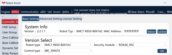
The xCore control system can be optionally equipped with an RSC safety controller, which is a safety module that complies with functional certification and performs various internal safety-related calculations and protections. The safety functions of the xCore control system are processed in parallel, forming a dual safety architecture. To ensure the data and parameter integrity of the safety controller, real-time data transmission adopts the FSoe communication mechanism for accurate transmission, while non-real-time data utilizes a secure synchronization mechanism with a synchronization time of 5s−10s. For robots equipped with safety controllers, the safeboard type is ROKAE_RSC as depicted in the figure below.
11.11.1 Changes after equipping safety controllers
In addition to the functions displayed on the subsequent safety controller configuration interface, there are several changes in the use of robots equipped with safety controllers.
11.11.1.1 Changes to robot motor state
"Safety stop state" is added to the robot state to indicate the safety state caused by the limits of the safety controller.

11.11.1.2 Added robot reset
When the robot is in any of the "emergency stop state", "safety gate state" or "safe stop state", to reset it to the "power-off state", you must complete the following 2 steps:
Step 1: Eliminate the operation or condition that triggers the above three states, such as rotating the emergency stop button to "OFF" position, clearing the safety gate trigger signal, removing the safety overrun factor, or disabling the corresponding safety limit;
Step 2: Click "Reset" button on the interface, and the robot will reset to the "power-off state".

11.11.1.3 Changes to the safety gate logic
For robots without safety controllers, when the robot is in automatic mode and receives the signal of safety gate closed, the robot will be powered off immediately. For robots with safety controllers, when the robot is in automatic mode and receives a signal of safety gate closed, the RL program will be suspended, and the robot will not be powered off. In this situation, the robot is unable to run the RL program or step through the RL program. If you want to restore the robot's status, you can: execute the signal to disconnect the safety gate, and click on the "Reset" signal on the HMI.
11.11.1.4 Time difference between zero calibration and friction parameter setting
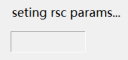
The zero information and the friction parameter information of the robot need to be synchronized to the safety controller to ensure the basic safety restriction function of the safety controller to be used normally. Therefore, when the user performs zero calibration or sets friction parameters, the controller will actively synchronize the updated parameters with the safety controller, which takes about 5s−10s to wait. At this point, the interface is as shown in the figure below, and the user is unable to operate and use the robot.
11.11.2 Safety DO configuration
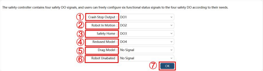
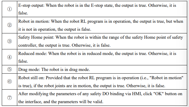
The safety controller has four channels of safety DO signals. The user can map several safety state signals to the four safety DOs.
No comments to display
No comments to display