
3. Wiring and Connections
3.1 Precautions for Wiring
3.1.1 General Precautions
3.1.2 Countermeasures against Noise

3.1.3 Recommended EMC Filters
To comply with the limits based on IEC/EN 61800-3 second environment (C2) the Drive and Motor must be installed with an EMC/RFI filter. For the whole system, 4 units of DX4 drives, recommended filters are:

These filters have been tested with cable lengths of 3m and 20m.
3.2 Power Supply (X1, X2)
3.2.1 Terminals Arrangement
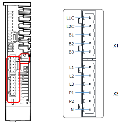
The power supply to Drive includes main circuit terminals and control circuit terminals.
Signal Diagram
Pin Layout
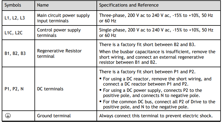
 Refer to DX4 Servo drive Product Manual, Chapter 3: Wiring and connections, for wiring diagram indications.
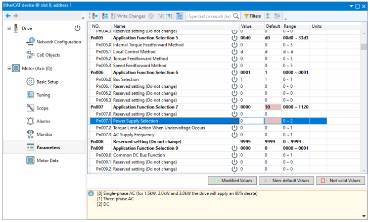
In case of using Single phase AC, parameter Pn007.1 has to be set to “0”:
3.2.2 External regenerative resistor
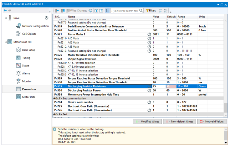
Use external regenerative resistor of 60W at 25Ohm in every servo drive.

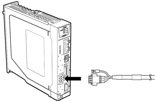
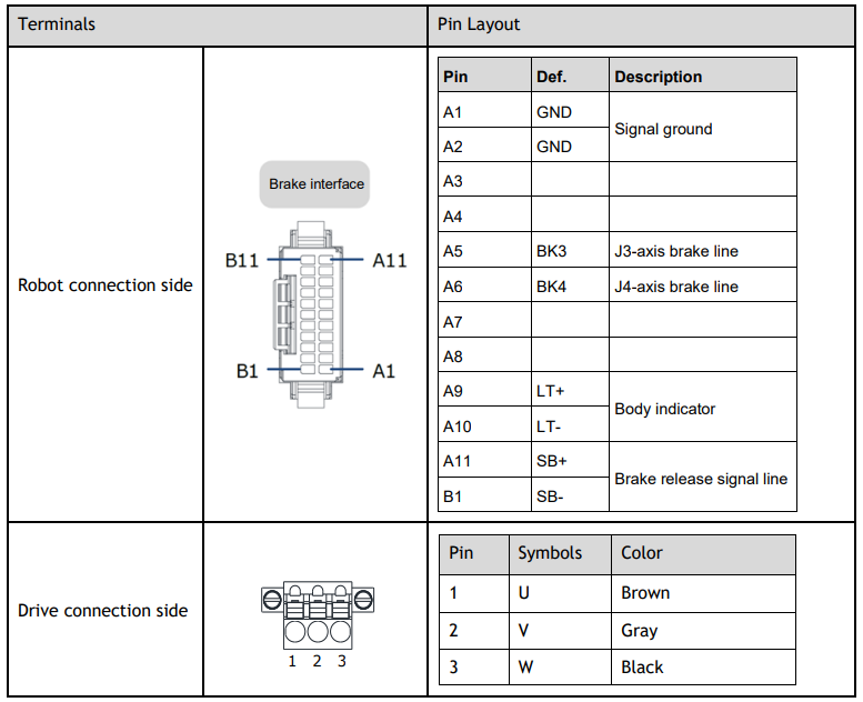
3.3 Motor Power (X3)
Connection Diagram
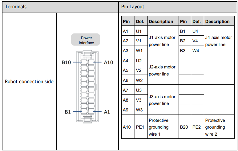
Terminals Arrangement
3.4 Encoder (X8)
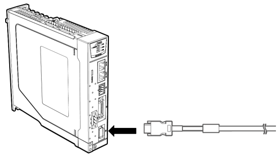
Connection Diagram
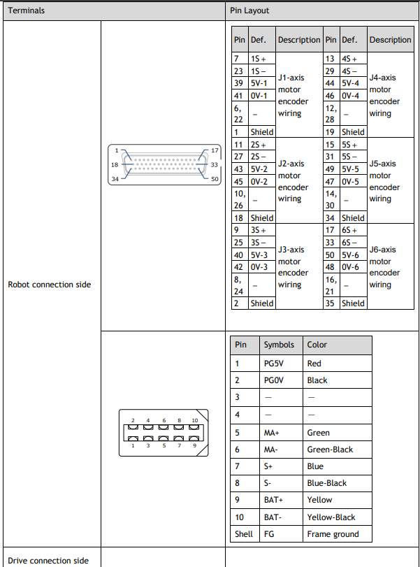
Terminals Arrangement
3.4.1 Encoder Battery Connection
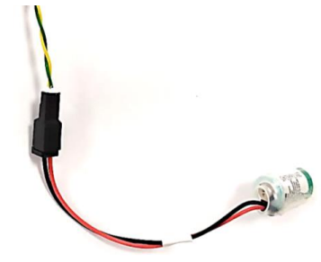
Absolute encoders are fitted on motors with an encoder type of L; e.g. MXL-02A0630LA222. These encoders require a battery supply to retain the absolute encoder data when the Drive power is removed.
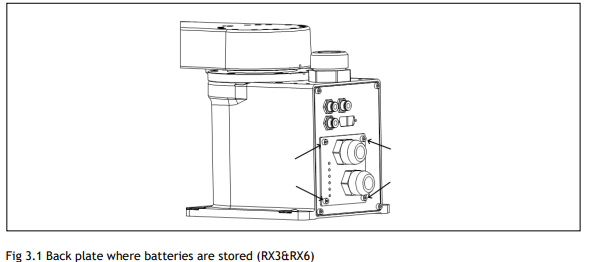
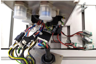
This battery supply is provided by an in-line battery fitted into the back of the robot which allows the encoder supply to be retained when the Encoder Cable is removed from the Drive

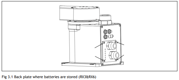
The following picture shows one of the four batteries that are installed in RX Scara series.
3.4.2 Finding calibration position
Calibrating is performed at the factory with no loads on the robot system, based on the robot parameters and the special tools and software. This calibration method is the most precise one. Every robot is provided with its calibration values.
The data of home position may be lost due to electrical or software problems. The stored zero position can be regarded as the reference when you perform calibration by teaching method.
The process consists of place robot in specific position by hand, allowing encoders to be at +-0.5 turn. At that position, the system can calculate the offset position if manufacture calibration values are set into the configuration software.
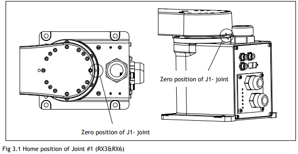
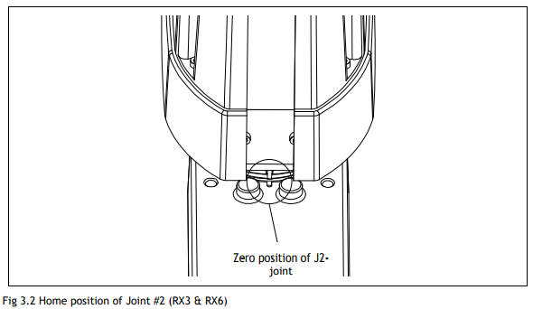
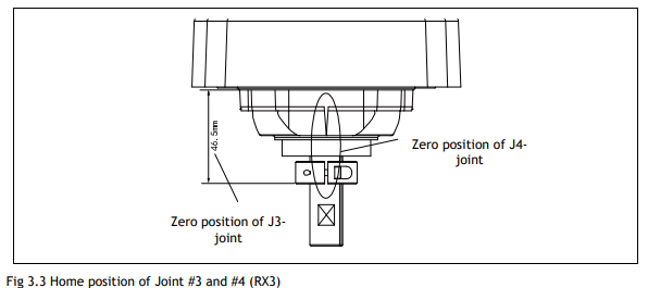
To calibrate the home position of J1, J2, J3 and J4 axis for RX3/RX6 Robot follow the procedures below:
1. Turn power off for all axis drives.
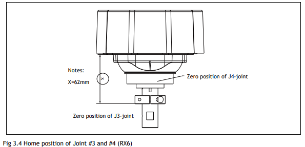
2. Move J1, J2, J3 and J4 to the position as shown in the figures.
3. Align the mark on the different arms as shown in the figures.
4. Replace batteries of J1, J2, J3 and J4 or unplug and then plug them again so absolute encoders multi turn is set to 0.
5. Set manufacture calibration values of every axis in system software.

To clear errors, go to Intelligent Drives Configuration in Motion Perfect and open the EtherCAT device with the error, like in the picture below:
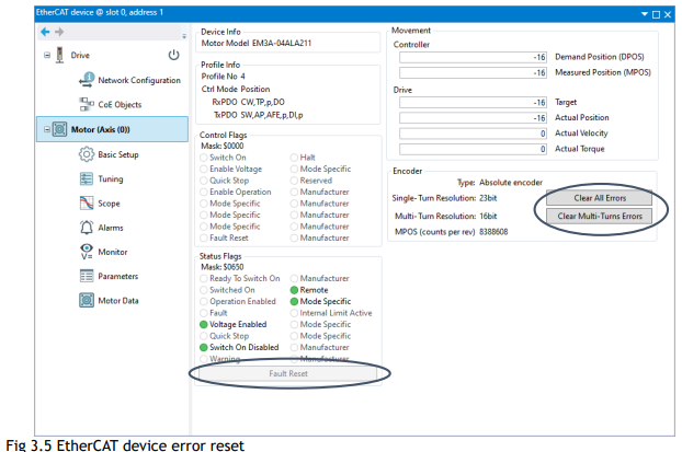
Press over “Clear Multi-Turn Errors”, then “Clear All Errors” and finally “Fault Reset”.
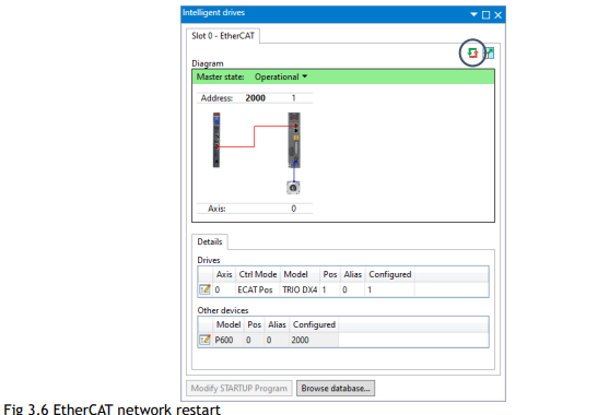
After do that with all error drives, restart the EtherCAT network.
ADD NEW HOME_POS COMMAND EXAMPLE TO SET CALIBRATED VALUES
No comments to display
No comments to display