
3. Setting Off End Effectors
3.1. Attaching an End Effector
Users are responsible for making their own end effector(s). Before attaching an end effector, observe these guidelines.
3.1.1. Shaft
Attach an end effector to the lower end of the shaft. For the shaft dimensions, and the overall dimensions of the Robot, refer to chapter 1. Specifications.
Use a split muff coupling with an M4 bolt or larger to attach the end effector to the shaft.
3.1.2.Brake release switch
Joint #3 cannot be moved up/down by hand because the solenoid brake is applied to the joint while power to the robot system is turned OFF. This prevents the shaft from hitting peripheral equipment in the case that the shaft is lowered by the weight of the end effector when the power is disconnected during operation, or when the motor is turned OFF even though the power is turned ON.
To move Joint #3 up/down while attaching an end effector, turn ON the Controller and press the brake release switch.
This button switch is a momentary type; the brake is released only while the button switch is being pressed.
The respective brakes for Joints #3 and #4 are released simultaneously.
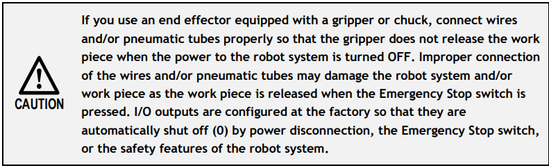
Be careful of the shaft while the brake release switch is being pressed because the shaft may be lowered by the weight of the end effector

3.1.3.Layouts
When you operate the robot with an end effector, the end effector may interfere with the Robot because of the outer diameter of the end effector, the size of the work piece, or the position of the arms. When designing your system layout, pay attention to the interference area of the end effector.
3.2. Attaching Cameras and Valves
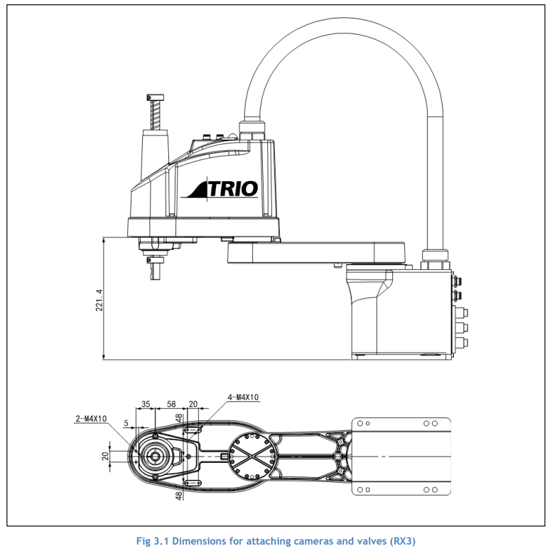
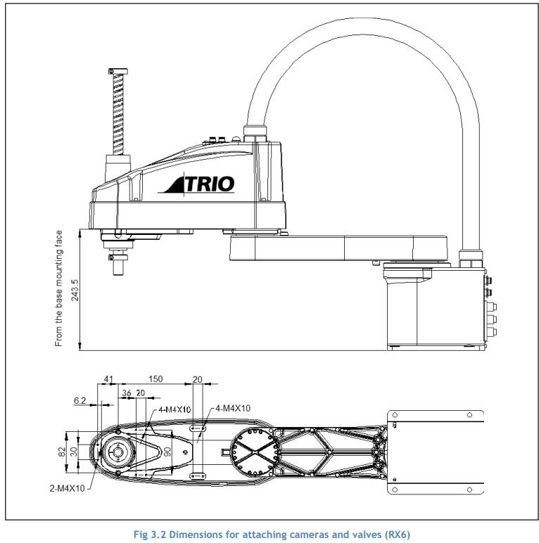
The bottom of the Arm #2 has threaded holes as shown in the figure below. Use these holes for attaching cameras, valves, and other equipment.
3.2.1.Equivalent weight
When you attach a camera or valve to the arm, calculate the weight as the equivalent of the shaft. Then add this to the load. Equivalent weight formula is shown below.
When you attach the equipment near Arm #2: 𝑊𝑀 = 𝑀(𝐿1)2/(𝐿1 + 𝐿2)2
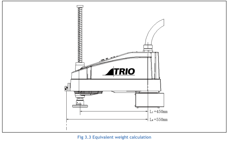
When you attach the equipment to the end of Arm #2: 𝑊𝑀 = 𝑀(𝐿𝑀)2/(𝐿2)2
𝑊𝑀 : equivalent weight
𝑀 : weight of camera etc.
𝐿1 : length of Arm #1
𝐿2 : length of Arm #2
𝐿𝑀 : distance from rotation centre of Joint #2 to centre of gravity
Example:
A “1kg” camera is attached to the end of the arm (550mm away from the rotation centre of Joint #2) with a load weight of “1kg”.
𝑀 = 1
𝐿2 = 450
𝐿M = 550
𝑊𝑀 = 1 × 5502 /4502 = 1.494 → 1.5 (Rounded up)
𝑊 + 𝑊𝑀 = 1+ 1.5 = 2.5
Enter “2.5” for weight parameter.
No comments to display
No comments to display