
5. Maintenance
This chapter describes maintenance inspections and procedures. Performing maintenance inspections and procedures properly is essential for preventing trouble and ensuring safety. Be sure to perform the maintenance inspections in accordance with the schedule.

5.1. Schedule for Maintenance Inspection
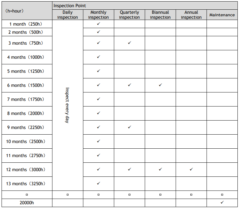
Inspection points are divided into five stages: daily, monthly, quarterly, biannual, and annual. The inspection points are added every stage. If the Robot is operated for 250 hours or longer per month, the inspection points must be added every 250 hours, 750 hours, 1500 hours, and 3000 hours operation.
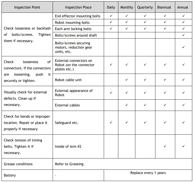
5.1.1.Inspection While Power is OFF (Robot is not operating)
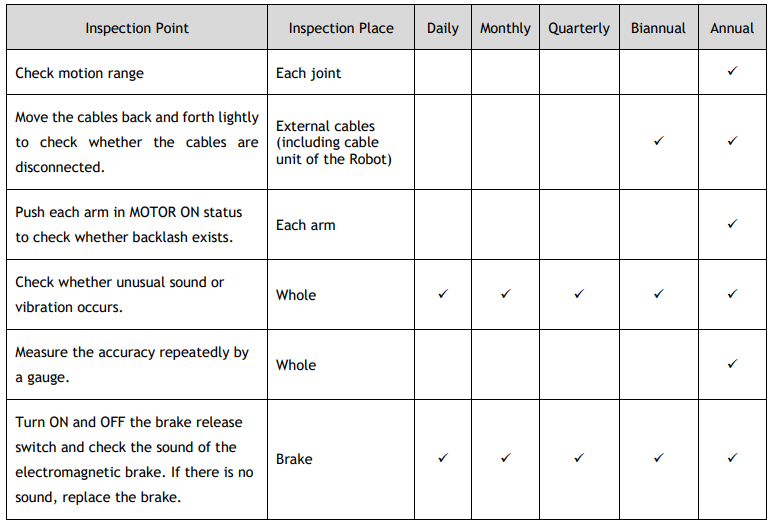
5.1.2.Inspection While the Power is ON (Robot is operating)
5.2. Greasing
The ball screw spline and reduction gear units need greasing regularly. Only use the grease specified in the following table.

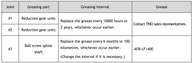
If the robot needs greasing, please contact us.
5.2.1.Greasing Procedures
Please cover the furniture and peripheral equipment, etc., in case that grease/oil falls.
(1) Turn the controller power ON.
(2) Move the arm to the position that Joint #3 is to its full motion distance.
(3) Press the brake release switch. Meanwhile, move the shaft to the upper limit.
(4) Turn off the controller.
(5) Clean up the remaining grease on the shaft and add new grease. Use tools such as a clean brush to paint the new grease until it covers the slot on the upper end of the shaft. Then clean up the remaining grease.
(6) Turn the controller power ON.
(7) Press the brake release switch. Meanwhile, move the shaft to the lower limit。
(8) Clean up the remaining grease on the shaft and add new grease. Use tools such as a clean brush to paint the new grease until it covers the slot on the lower end of the shaft. Then clean up the remaining grease
(9) Press the brake release switch. Meanwhile, move the shaft up and down several times to apply the grease evenly. Then clean up the remaining grease

5.3. Tightening Hexagon Socket Head Cap Bolts
Hexagon socket head cap bolts are used in places where mechanical strength is required. (A hexagon socket head cap bolt will be called a “bolt” in this manual.)
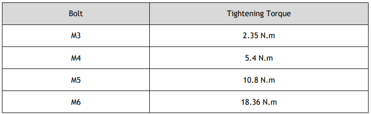
These bolts are fastened with the tightening torques shown in the following table. When it is necessary to refasten these bolts in some procedures in this manual (except special cases as noted), use a torque wrench so that the bolts are fastened with the appropriate tightening torques as shown below.
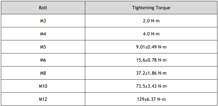
Refer below for reducer tightening bolt
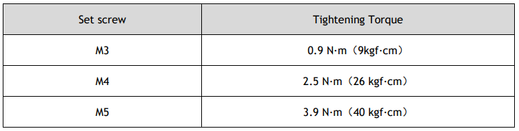
Refer below for the set screw.
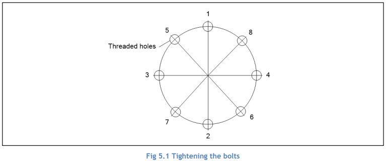
The bolts aligned on a circumference should be fastened in a crisscross pattern as shown in the figure below. Do not fasten all bolts securely at one time. Divide the number of times that the bolts are fastened into two or three and fasten the bolts securely with a hexagonal wrench. Then, use a torque wrench so that the bolts are fastened with tightening torques shown in the table above.
5.4. Maintenance of the Belt

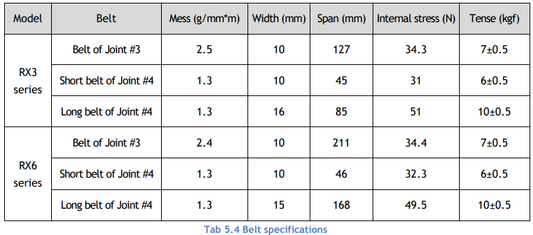
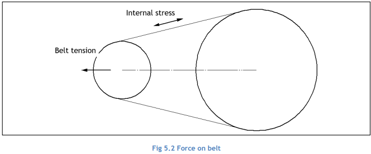
5.4.1.Belt specifications
5.4.2.Failure mode of timing belt
Periodical maintenance of the timing belt should be performed.
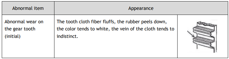
Check the appearance. When abnormal situation occurs, replace the abnormal part.
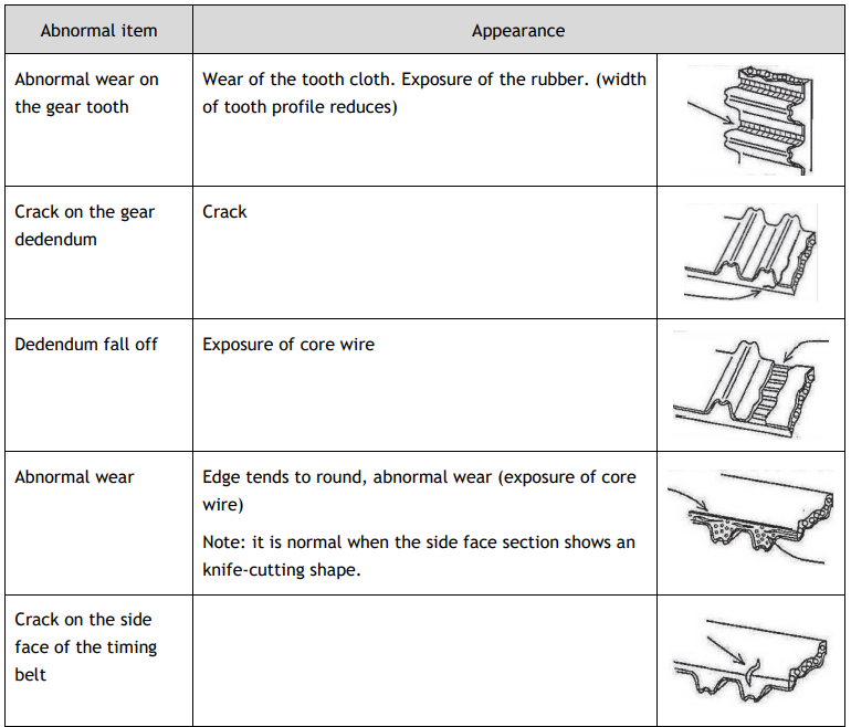
Replace the timing belt when belt failure occurs. After replacing the timing belt, re-tight the belt tension and re-calibrate the zero position.
No comments to display
No comments to display