
3. Specification
3.1. Robot configuration
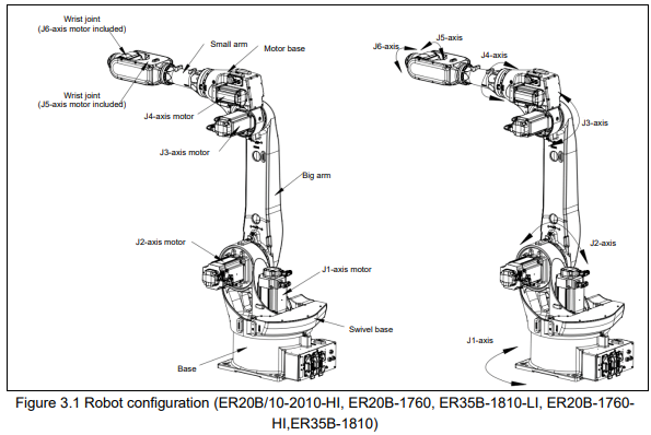
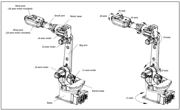
Figure 3.2 Robot configuration (ER12B-1510-LI, ER12B-1510)
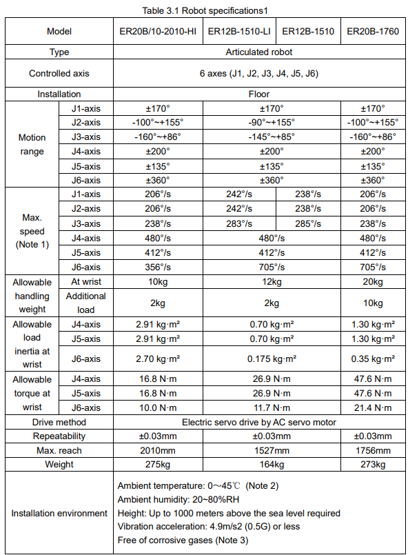
(Note 1) During short distance motions, the axis speed may not reach the maximum value stated.
(Note 2) When the robot is used in low temperature environment that is near 0℃ or not operated for a long time in the environment that is less than 0℃ in a holiday or the night, collision detection alarm may occur since the resistance of the drive mechanism could be high immediately after starting the operation. In this case, we recommend performing the warm up operation for several minutes.
(Note 3) Contact the service representative, if the robot is to be used in an environment or a place subjected to hot/cold temperatures, severe vibrations, heavy dust, cutting oil splash and or other foreign substances.
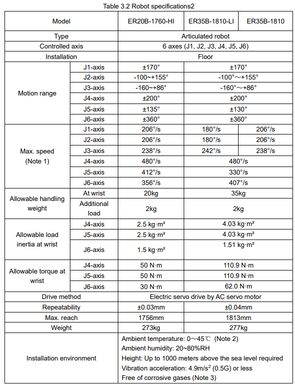
(Note 1) Short-distance movements may not reach the maximum speed of each axis. The maximum range of motion for each axis is measured when the robot is in the zero position, but the actual motion may be limited by the position of other axes.
(Note 2) When using the robot in low-temperature environment that is near 0°C, or when leaving the robot stopped in environments below 0°C during rest days or overnight, collision detection alarms may occur due to high resistance in the movable parts during the initial startup. In such cases, it is recommended to perform several minutes of warm-up operation.
(Note 3) For usage in high-temperature, low-temperature, vibrating, dusty, or environments with high concentrations of cutting oil, please consult ESTUN for guidance.
3.2. External dimensions and operating space
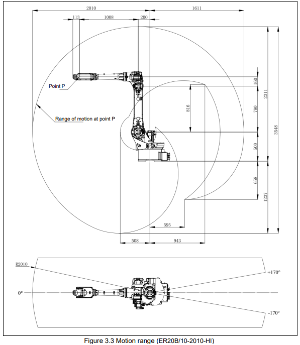
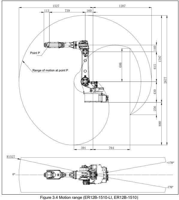
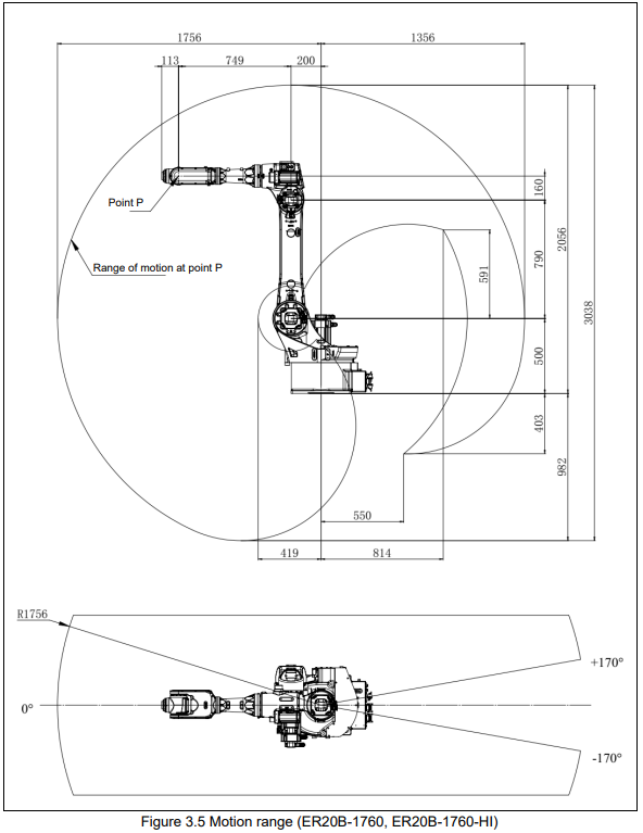
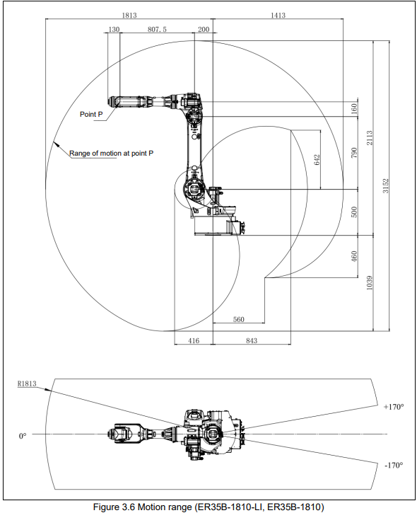
The following figures illustrate the range of motion of the robot and serves as a reference for selecting and setting up the robot's installation position. When installing peripheral devices, it is important to ensure they do not interfere with the main body of the robot and its range of motion.
3.3. Zero point position and motion limit
Zero point and motion range are provided for each controlled axis. Exceeding the software motion limit of a controlled axis is called overtravel (OT). Overtravel is detected at both ends of the motion limit for each axis. The robot cannot exceed the motion range unless there is a loss of zero point position due to abnormalities in servo system or system error.
In addition, the motion range limit by a fixed mechanical stopper is also prepared to improve safety.

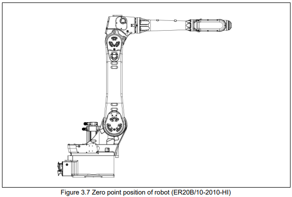
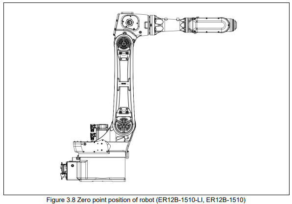
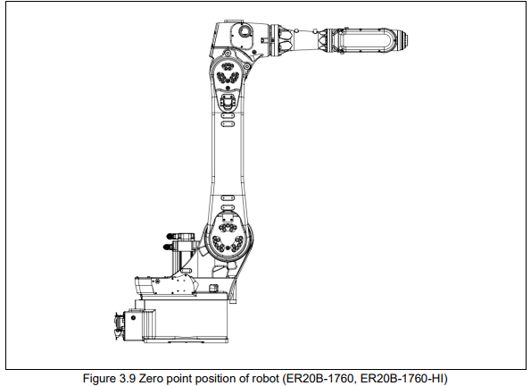
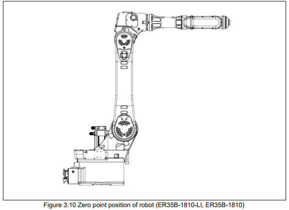
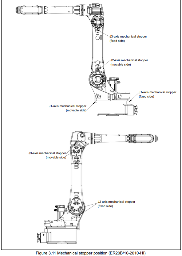
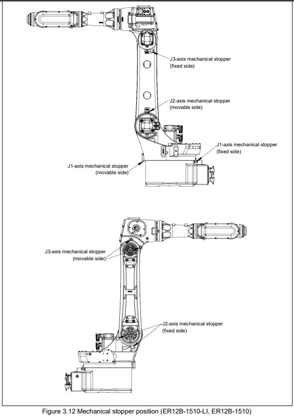
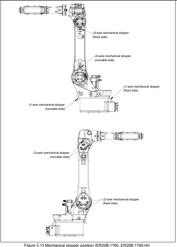
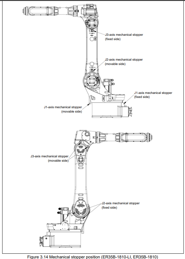
Refer to system operation manual for more information about setting motion range.
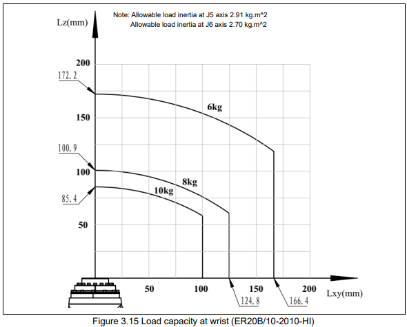
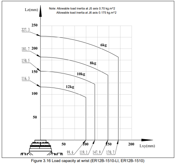
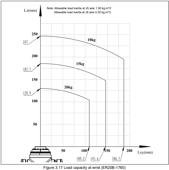
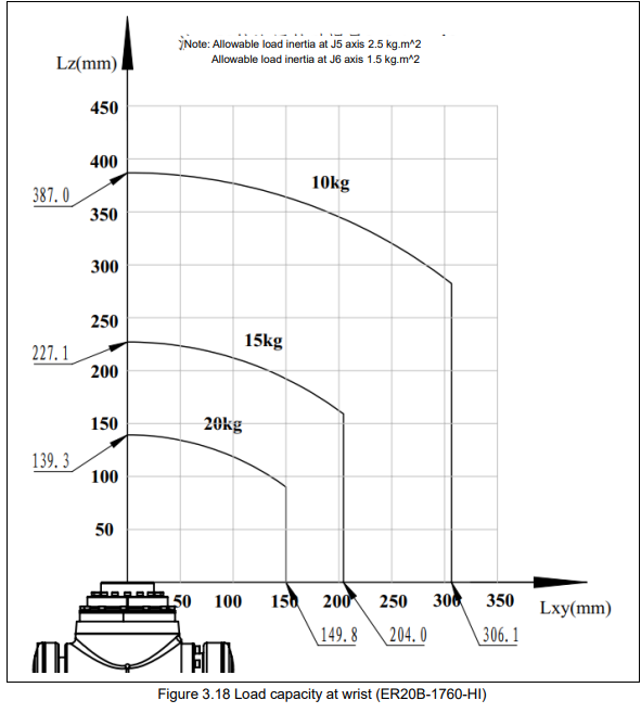
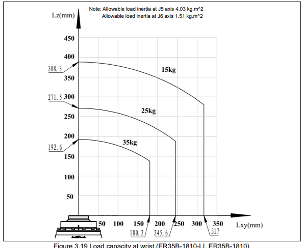
3.4. Wrist load condition
Robot load capacity (including weight of gripper or welding gun) coincides with robot model.
Observe restrict of load torque and load inertia strictly.

Refer to ESTUN robot bearing capacity calculation table when calculate load torque and load inertia. Contact ESTUN sales representatives for more detail.
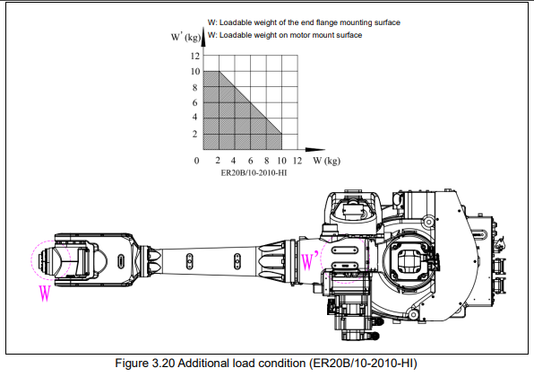
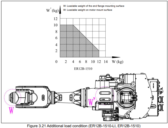
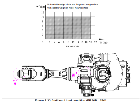
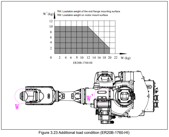
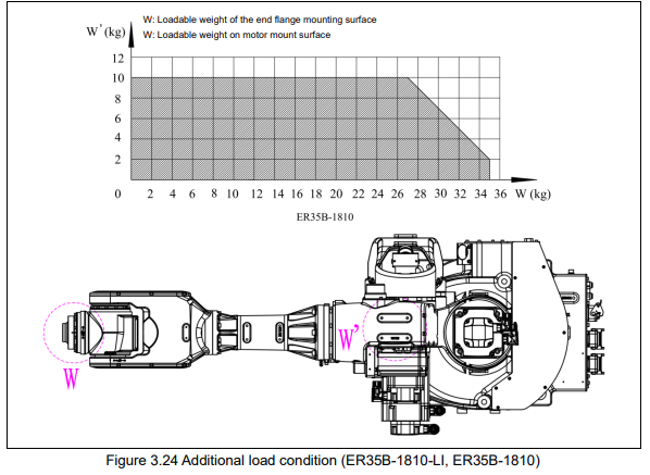
3.5. Additional load conditions
The robot may have additional loads. Additional load condition is shown as below
No comments to display
No comments to display