
2. Installation
2.1 Environmental requirements
Install the robot system in an environment satisfying the following conditions.
The ambient temperature should be at - 5 ℃and 55 ℃during operation, and -20 ℃to 85 ℃ during handling and maintenance.
RH shall not above 95% RH without condensation.
Places with less dirt, dust, oil fume and water.
No inflammables and corrosive liquids and gases in the working area.
Places with minor vibration or impact to the control cabinet (vibration below 0.5G).
No electrical interference source nearby (e.g. gas shielded welding TIG equipment, etc.).
No potential risk of collision with mobile equipment (e.g. forklift).
2.2 Installation location
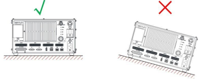
For a standard installation scenario, the table top shall be placed stably, which should be flat without inclination and deformation.
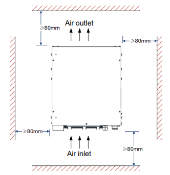
The space for installation is shown in the figure below, with a sufficient heat dissipation space reserved for installation.
2.3 Way to install
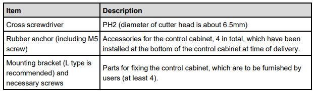
Following tools shall be prepared prior to installation.
2.3.1 Horizontal installation
Installing steps
Install the control cabinet horizontally by following the steps below:
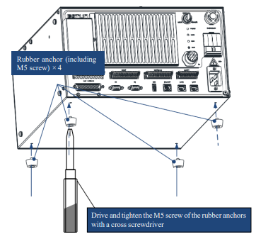
Step 1: Mount the four rubber anchors to the bottom of the control cabinet and fasten them using a cross screwdriver, as shown in the figure below.
[Note] As the rubber anchors have been installed at the bottom of the control cabinet at time of delivery, so users may skip this step.
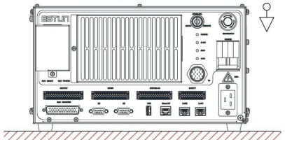
Step 2: Complete the horizontal installation by putting the control cabinet on the table in the direction as shown in the figure below.
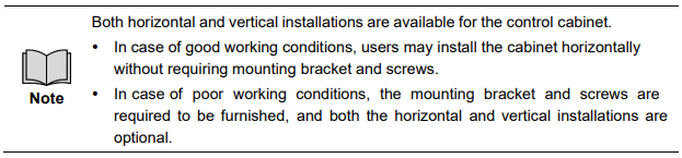
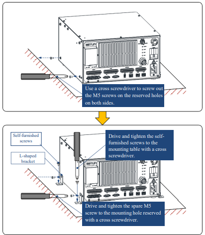
Step 3 (optional): In case of poor working condition (e.g. easy to generate vibration), selffurnished mounting bracket (L type is recommended) as well as the screws shall be used to fix the control cabinet.The horizontal installation of the control cabinet has been finished at this moment.
Mounting dimensions
The figure below shows the mounting dimensions for horizontal installation.
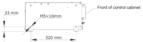
[Note] The size of the screw and L-shaped bracket on the mounting table should be customized based on needs. M5 screw is recommended.
2.3.2 Vertical installation
Installing steps
Install the control cabinet vertically by following the steps below:
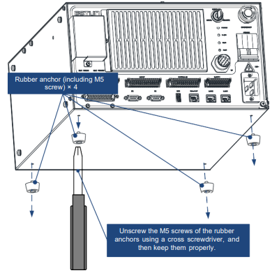
Step 1: Loosen the M5 screws of the four rubber anchors using a cross screwdriver, and then keep the rubber anchors (including M5 screws) properly.
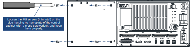
Step 2: Loosen the M5 screws (4 in total) on the side hanging no nameplate of the control cabinet with a cross screwdriver, and keep them properly (for standby).
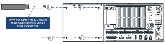
Step 3: Mount 4 rubber anchors (including M5 screws) into the mounting holes on the side hanging no nameplate of the control cabinet.
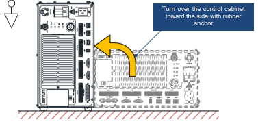
Step 4: Turn over the control cabinet toward the side with rubber anchor, and put it on the table stably.
Step 5: Fix the control cabinet on the installing surface according to figure below by using the self-furnished bracket, screws and the M5 screws supplied for standby use.
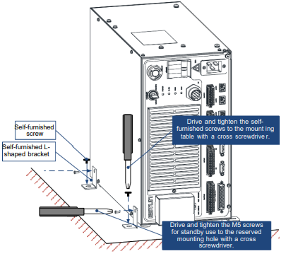
Step 6: For both sides of the control cabinet, stabilize the control cabinet on the installing surface in the same way as above using the self-furnished mounting bracket and screws as well as the standby M5 screws.The vertical installation of the control cabinet has been finished at this moment.
Mounting dimension
Following figure shows the mounting dimensions for vertical installation
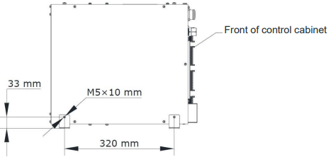
[Note] The size of the screw and L-shaped bracket on the mounting table should be customized based on needs. M5 screw is recommended.
2.4 Install the encoder cable clip
After installing the control cabinet horizontally, users need to mount the encoder cable clip.
Prepare the following tools prior to installation.

Mount the encoder cable clips by taking following steps.
Step 1: Loosen the screws under the encoder interface using a cross screwdriver to (2 screws in total) and keep them properly for later use.
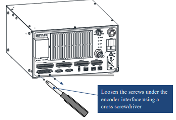
Step 2: Use the encoder cable clip and spare screws. Mount the encoder cable clip to the control cabinet according to the following diagram.
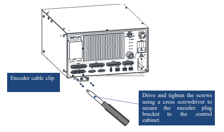
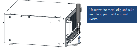
Step 3: Before inserting the encoder plug, unscrew the metal clip according to the diagram below; take out the metal clip and screw on it, and keep it properly for later use.
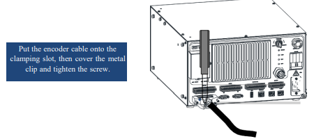
Step 4: After the encoder plug is inserted, put the encoder cable onto the clamping slot, then cover the metal clip and tighten the screw.
After the encoder plug is properly inserted, put the encoder cable onto the clamping slot, then cover the metal clip and tighten the screw.
Step 5: Tighten the fastening bolts on both sides of the encoder plug.

The encoder cable clip is mounted at this moment.
No comments to display
No comments to display