
3. Wiring and Connection
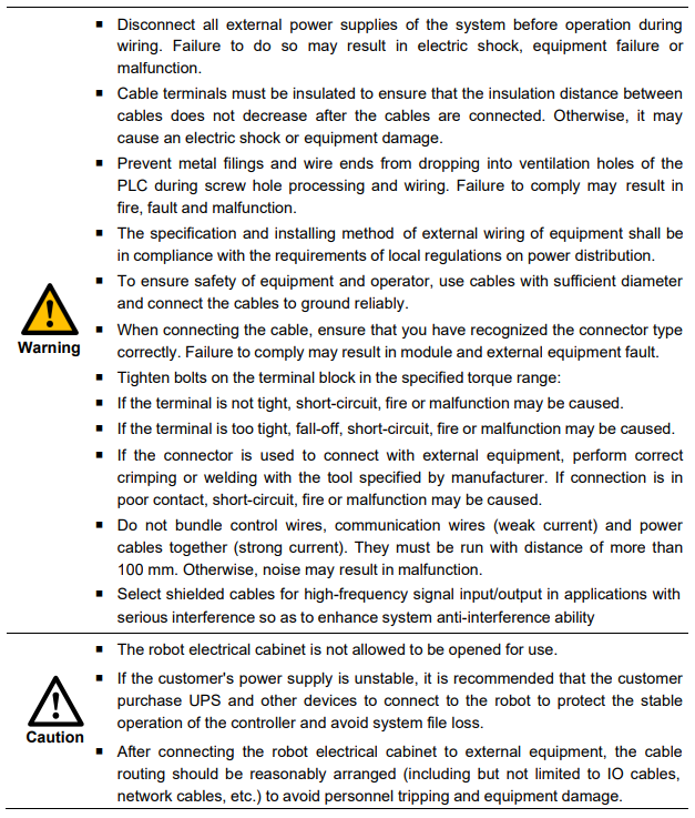
3.1 Precautions during wiring and connection
The product installation, wiring, maintenance and inspection shall only be performed by professional maintenance workers who have received the necessary electrical training and understood enough electrical knowledge.
3.2 Pin Description of IO Class Terminals
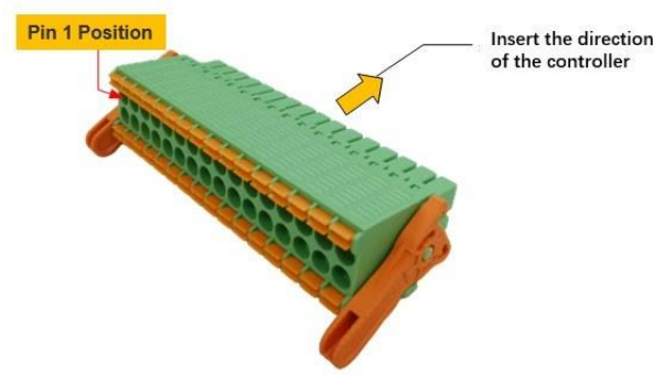
Please pay attention to the pin order of the wiring terminals and make the correct wiring according to the physical example shown in the figure below.
The pin order description of this terminal block is applicable to the following terminal blocks:
⚫ SYSTEM-IO
⚫ INPUT
⚫ OUTPUT
⚫ SAFETY
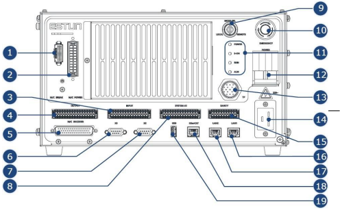
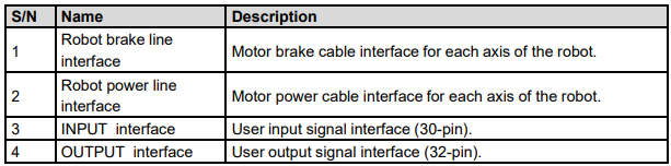
3.3 Interface specification
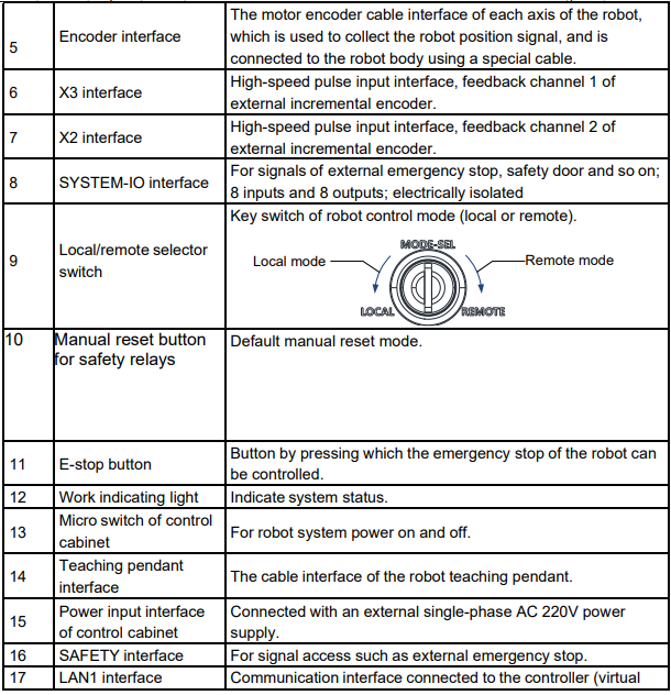

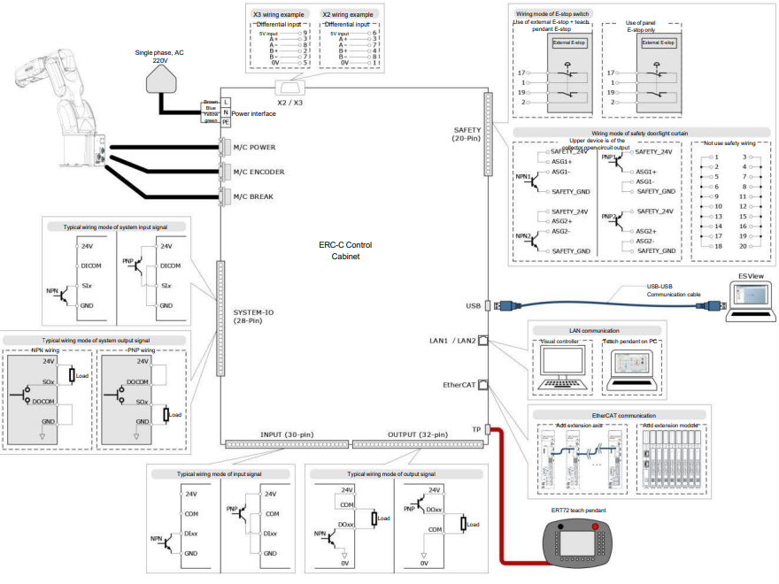
3.4 Basic connection diagrams
3.5 Instructions of indicator lamp
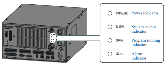
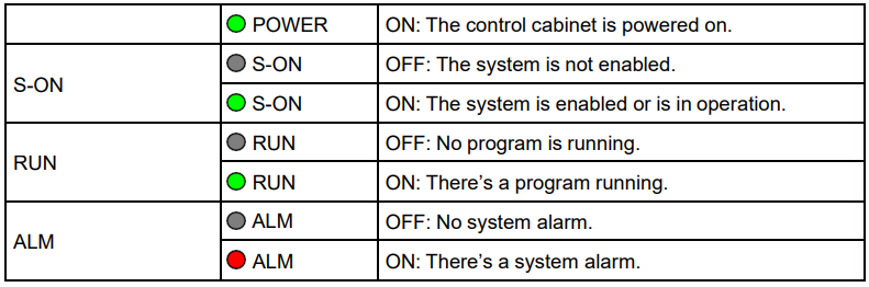
There’re 4 working indicator lamps arranged in the control cabinet, which are used to indicate the working state of the system, as detailed in the table below.

3.6 Power supply wiring
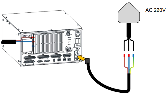
The control cabinet employs single-phase AC 220V power supply. Make the power line as per the following diagram and make the correct connection.
The control cabinet has been provided with the appropriate cables by ESTUN, while the plug shall be furnished by users. Any cables selected additionally by users shall be in compliance with the safety regulations, and the rated current shall be 16A.

3.7 Teaching pendant wiring
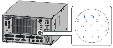
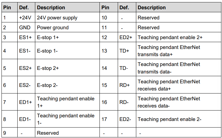
3.7.1 Definition of teaching pendant interface
3.7.2 Way to connect teaching pendant
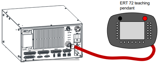
This product is provided with an ERT 72 teaching pendant for the purpose of robot teaching and programming. The connection diagram is shown in the figure below. Refer to its programming manual for the detailed operation of the teaching pendant.
3.8 Power wiring
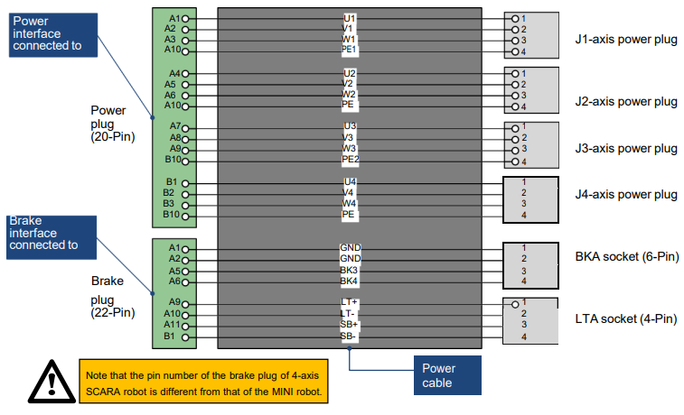
3.8.1 Definition of power interface/brake interface
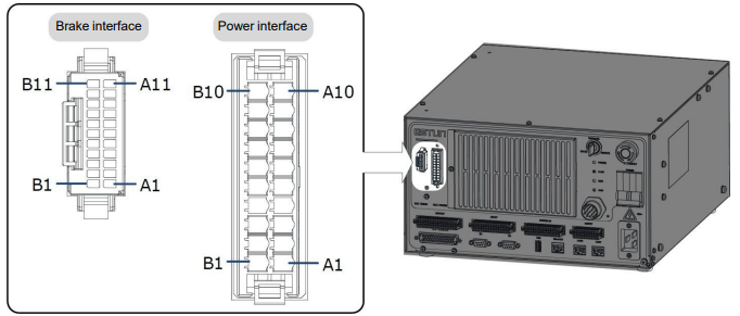
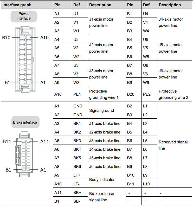
[Note] The power line signal associated with each axis shall be U/V/W/BK/PE.
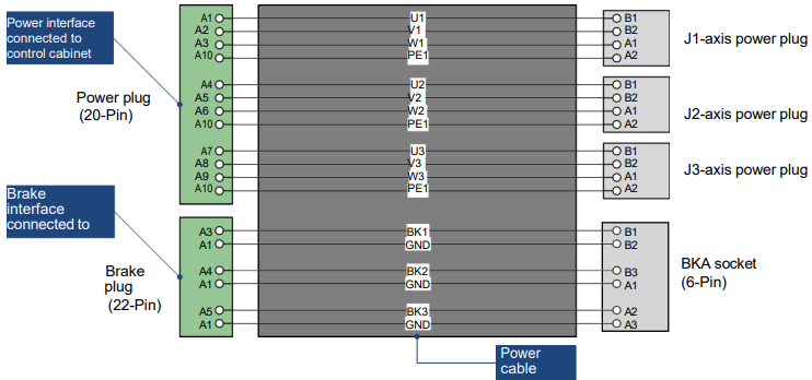
3.8.2 Specification of wires & cables
Cable connected to 3-axis MINI robot
Cable connected to 4-axis MINI robot
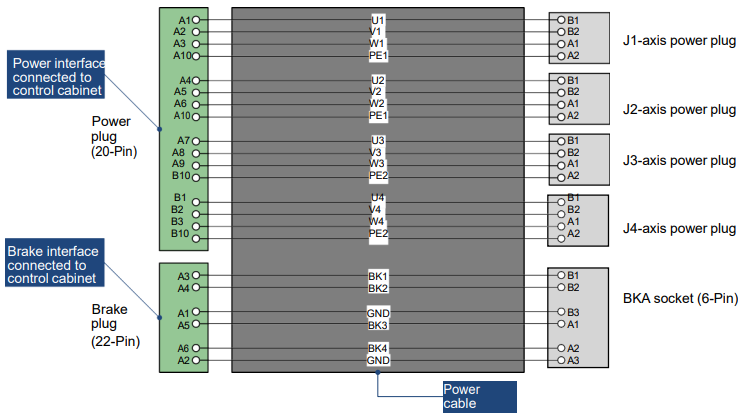
Cable connected to 6-axis MINI robot
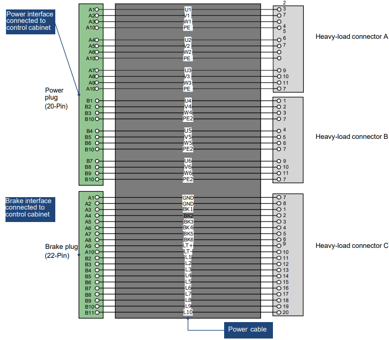
Cable connected to 4-axis SCARA robot
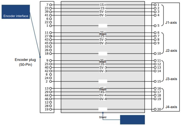
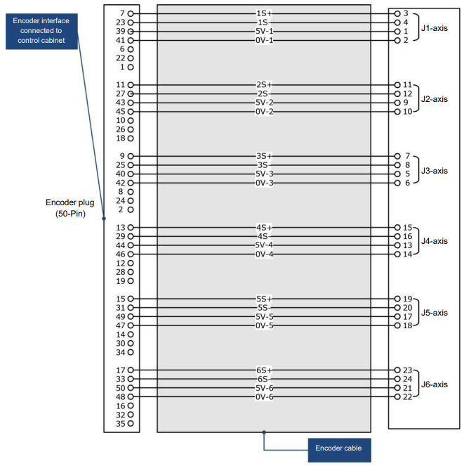
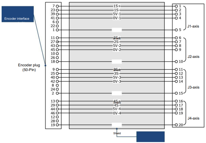
3.9 Encoder wiring
3.9.1 Definitions of encoder interfaces
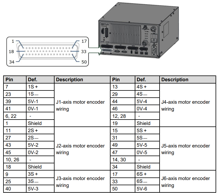

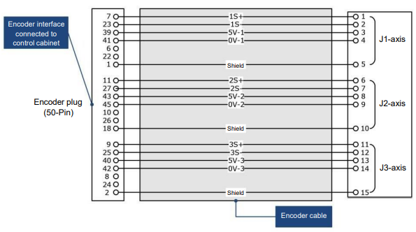
[Note] The encoder signal associated with each axis shall be S+/S﹣/5V/0V/Shield.
All pins not listed in the table above are reserved.
3.9.2 Specification of wires & cables

Cable connected to 3-axis MINI robot
Cable connected to 4-axis MINI robot
Cable connected to 6-axis MINI robot
Cable connected to 4-axis SCARA robot
3.10 SYSTEM-IO wiring
3.10.1 Definition of system I/O interface
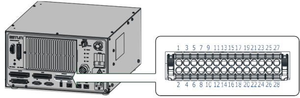
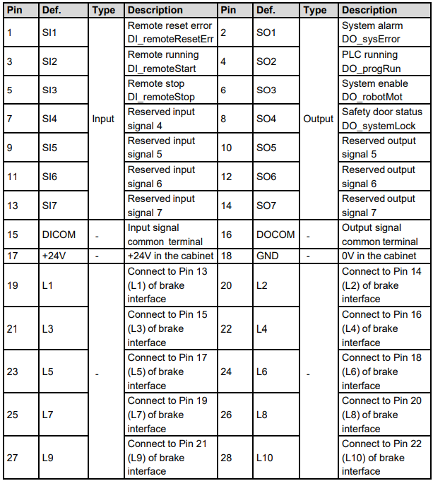
【Note】Please pay attention to the pin order of the wiring terminals. For a description of the pins, please refer to "3.2 Pin Description of IO Class Terminals".
3.10.2 Wiring of system input signal
Signal specification
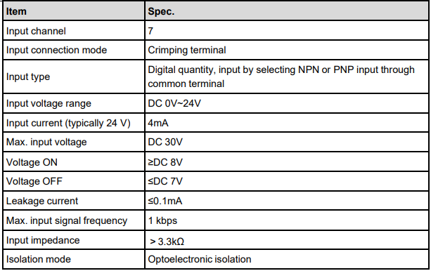
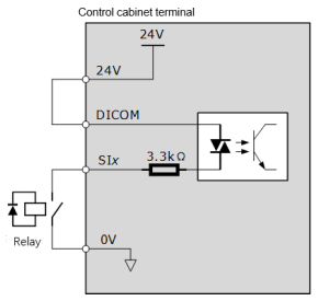
The upper device is a relay output
The wiring examples for using 24V power supply in-cabinet is as follows
The wiring examples for using 24V power supply out- cabinet is as follows
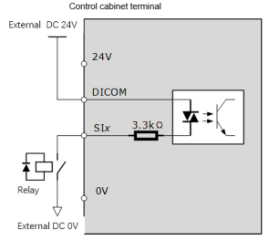
Use 24V power supply wiring out cabinet, please use a single power supply.
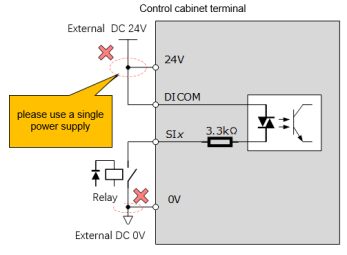
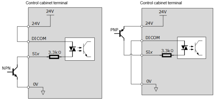
The upper device is open collector output
The wiring examples for using 24V power supply in-cabinet is as follows
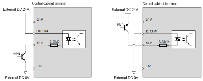
The wiring examples for using 24V power supply out-cabinet is as follows
3.10.3 Wiring of system output signal
Signal specification
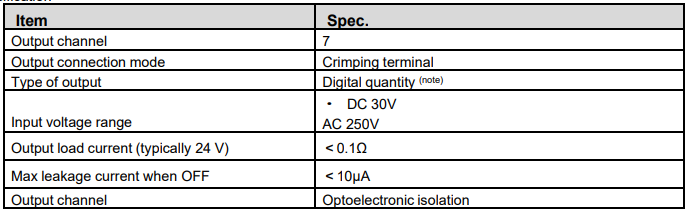
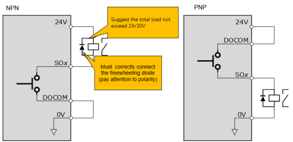
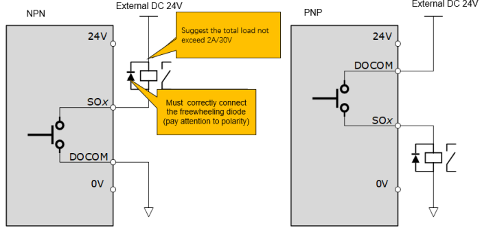
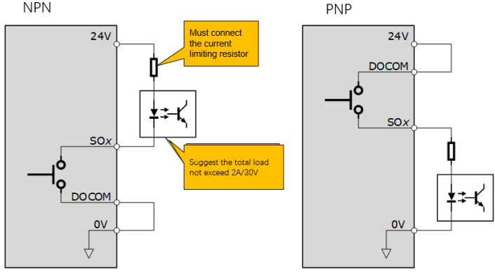
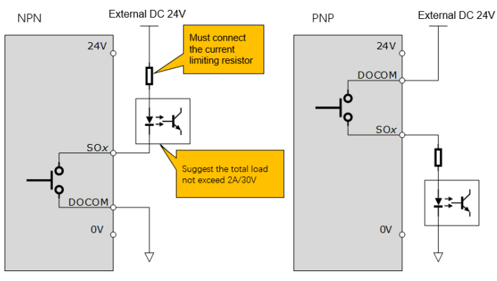
【Note】NPN or PNP is available to users based on the type of load for the wiring mode ofsystem output signal
Drive the relay load
The wiring examples for using 24V power supply in-cabinet is as follows
The wiring examples for using 24V power supply out-cabinet is as follows
Drive the optocoupler load
The wiring examples for using 24V power supply in-cabinet is as follows
The wiring examples for using 24V power supply out-cabinet is as follows
3.11 INPUT wiring
3.11.1 Definition of input signal
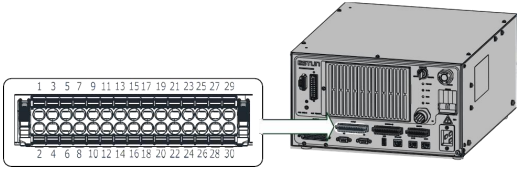
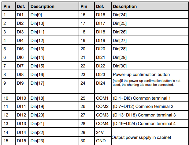
NOTE Please pay attention to the pin sequence of the terminal when the upper device outputs open collector, For the description of pins, please refer to "3.2 Pin Description of IO Class Terminals”
3.11.2 Input signal specification
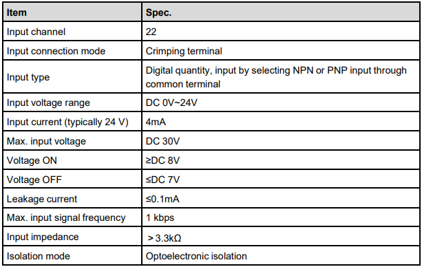
3.11.3 Wiring rules of input signal
Wiring in four groups: COM1 and DI1~DI6 are the Group 1; COM2 and DI7~DI12 are the Group 2; COM3 and DI13~DI18 are the Group 3, while COM4 and DI19~DI22 are the Group 4.
NPN mode: When COMx is connected to 24 V, and 0V is input at DIxx terminal, the input signal is valid (optocoupler is ON);
PNP mode: When COMx is connected to 0V, and 24V is input at DIxx terminal, the input signal is valid (optocoupler is ON).
3.11.4 Wiring examples of input signal
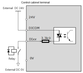
The upper device is a relay output
The wiring examples for using 24V power supply in-cabinet is as follows
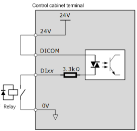
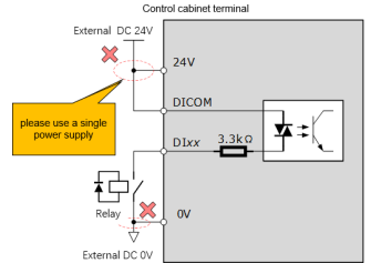
The wiring examples for using 24V power supply out-cabinet is as follows
The wiring out-cabinet use 24V power supply, please use a single power supply
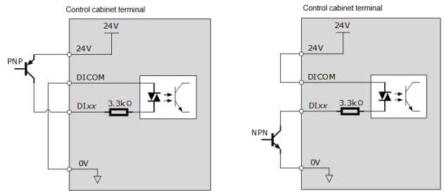
The upper device is open collector output
The wiring examples for using 24V power supply in- cabinet is as follows
The wiring out-cabinet use24V power supply, please use a single power supply
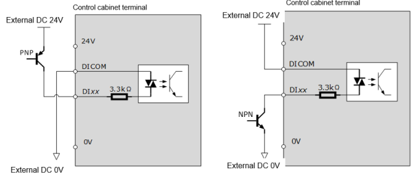
3.11.5 Signal for power-up confirmation button
The wiring schematic of the power-up confirmation button is shown below.
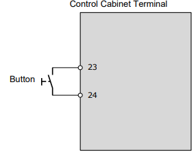
Please note the following when connecting and using the power-on confirmation button.
⚫ When the power-up confirmation button is used, a normally open button must be connected externally;
when the function is not used, keep the short connector connected.
⚫ Turn on the control circuit and make sure that there is no alarm in the system, the emergency stop button and the safety relay have been reset, then press the power-up confirmation button to turn on the main circuit.
⚫ If the system has an alarm, emergency stop, etc., it will automatically disconnect the main circuit, so please carry out troubleshooting. Then press the power-up confirmation button again to turn on the main circuit.
⚫ When switching between automatic and manual mode, the main circuit will be disconnected automatically, so please press the power-up confirmation button to turn on the main circuit.
3.12 OUTPUT wiring
3.12.1 Definition of output signal
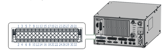

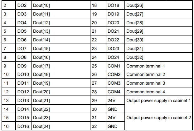
NOTE Please pay attention to the pin sequence of the terminal when the upper device outputs open collector, For the description of pins, please refer to "3.2 Pin Description of IO Class Terminals”
3.12.2 Output signal specification
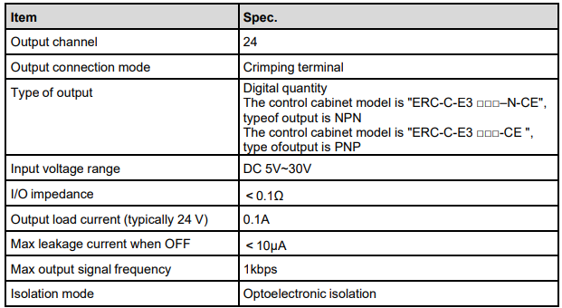
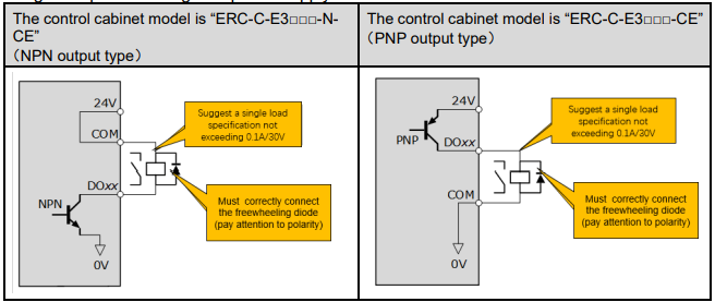
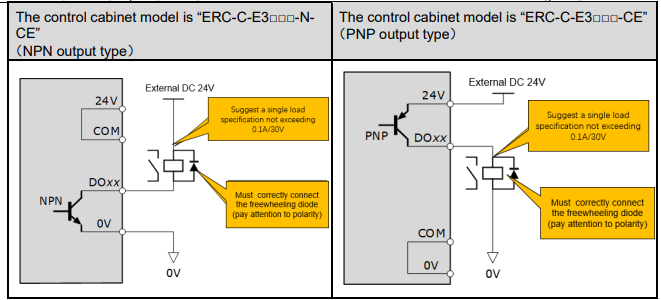
【Note】Please ensure correct wiring, improper wiring can cause malfunction.
When the signal connection distance is too long, it is recommended to use shielded cables and maintain good grounding
3.12.3 Wiring example of output signal
When driving the relay load
The wiring examples for using 24V power supply in cabinet is as follows
The wiring examples for using 24V power supply outside the cabinet is as follows
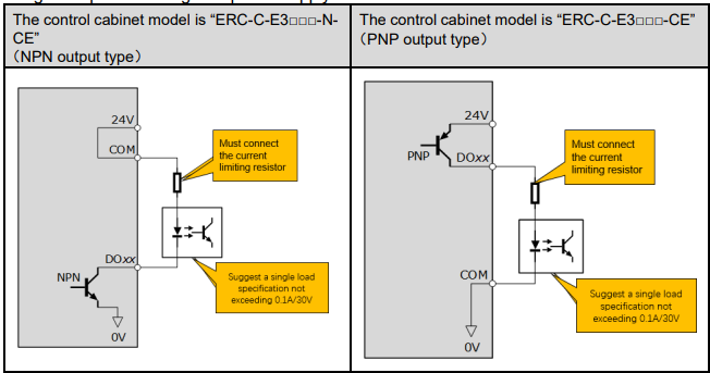
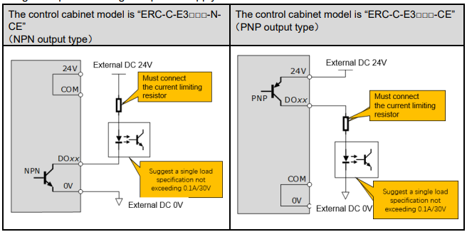
When driving the optocoupler load
The wiring examples for using 24V power supply inside the cabinet is as follows
The wiring examples for using 24V power supply outside the cabinet is as follows
3.13 SAFETY wiring
3.13.1 Definition of SAFETY interface
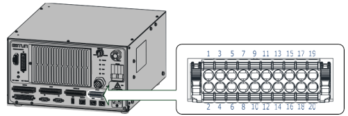
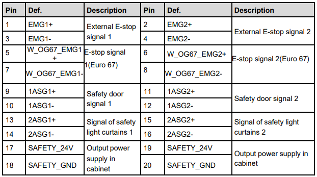
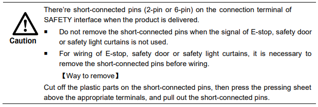
3.13.2 Removal of short-connected piece
3.13.2 E-stop wiring method
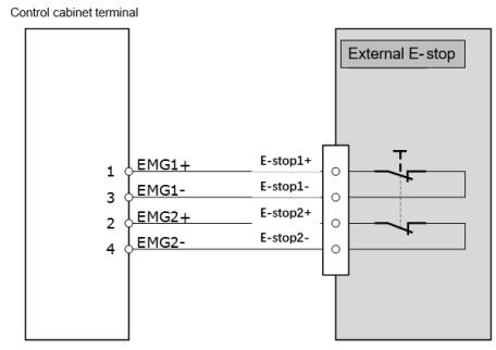
E-stop is used for emergency treatment, and serial access is made with normally-closed switch (e.g. knob, mushroom head E-stop switch). By pressing an E-stop switch, the action signal will send the signal to control cabinet through the optocoupler. At the same time, the main circuit power supply of the servo will be disconnected for the purpose of emergency braking.
Note
E-stop is of a normally-closed contact connection, which is of doublecircuit structure. Any emergency stop disconnection will trigger the E-stop feature.
Use of external E-stop
Do not use external E-stop
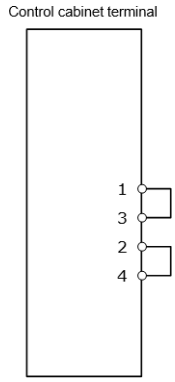 [Note]When teaching pendant is not connected, Teaching pendant E-stop default normally closed
Emergency stop output logic (Euro 67)
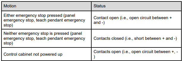
[Note]: Emergency stop signals do not include external user emergency stops (in order to meet the requirements of European Regulation 67).
3.13.3 Wiring method of safety door and safety light curtains
Safety door and safety light curtains are used to control the protective fence and protective door of the robot.

When the upper device is of the relay output
the wiring examples for in-cabinet 24 V powersupply are as follows.
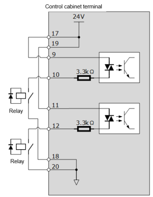
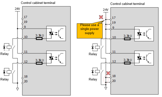
the wiring examples for out-cabinet 24 V powersupply are as follows.
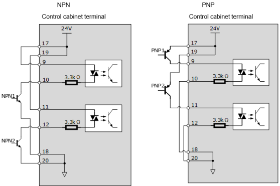
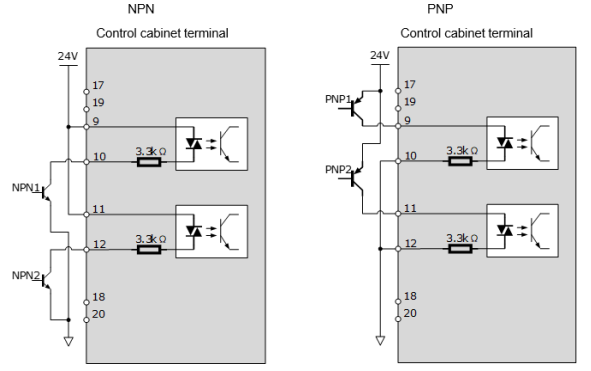
When the upper device is of the collector open circuit output
the wiring examples for in-cabinet 24 V power supply are as follows.
the wiring examples for out-cabinet 24 V power supply are as follows.
3.14 Communication wiring
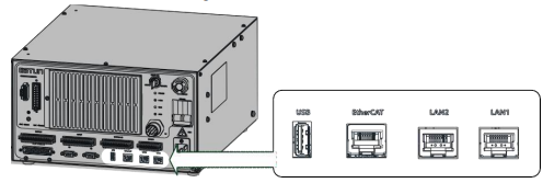
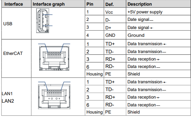
3.14.1 Definition of communication signal
3.14.2 Connection to PC
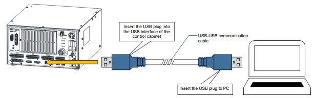
Users may connect the PC to the control cabinet using USB-USB communication cable to allow the use of ESView software.
Connection diagram
Specification of wires & cables
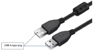
Users may choose the USB-USB communication cable as provided by ESTUN, or purchase the market available products. The USB A-type plug is used to connect the PC and the control cabinet.
3.14.3 Connection to EtherCAT communication device
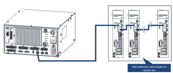
The control cabinet can be connected to devices supporting EtherCAT communication as the master station in EtherCAT communication, for example, the Trio module and ED3S servo driver (to be used as expansion axis).
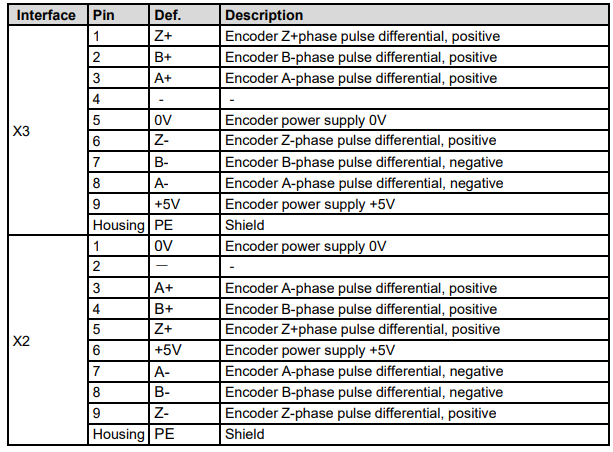
3.15 X2/X3 wiring
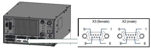
X2 and X3 are the interfaces of high-speed pulse input signal, through which users can access external incremental encoder. The control cabinet is allowed to detect the feedback signal, convert it into data information and send to the supporting software.
3.16 Built-in safety relay reset mode description
The built-in safety relay is configured as manual reset mode by default when it is shipped out from the factory, and the reset button on the panel must be pressed and released manually before each time when the cabinet is on mains, so that the cabinet can be on mains normally.
When customers need the built-in safety relay to be configured as automatic reset mode, they need to contact the technical service personnel to modify the reset mode of the internal safety relay, the specific configuration methods are as follows:
USR22 configuration
1. Initially three lights blink red, at this time you need to configure a mode to work normally.
2. Modes are P.01~P.0N, CUS mode, select P.0N, press "↑", the parameter of t can be selected as the time of delayed power failure, such as 0.5, 1, 1.5, etc., because the controller has a planning to stop, therefore, generally press "+" configure as t=1s, then press "↑", transfer to sto interface, long press "↑" to confirm the appearance of "----", then restart, the configuration takes effect.
3. If you need to change the configuration of safety relay, you need to press "↑" and "+" buttons at the same time for more than five seconds, the factory parameters will be restored, and then you can modify the configuration parameters again.
4. When P.01 (manual reset) is selected, X1 and X4 of the safety relay can not be shorted, when there is no emergency stop pressed, CH1 and CH2 will light green and Mode will light blue, at this time, when the white manual reset button is pressed, Mode will light green and the contacts of the safety relay will be closed.
5. When P.02 (automatic reset) is selected, it is necessary to short X1 and X4 of the safety relay, and when no emergency stop is pressed, the automatic reset is performed, CH1, CH2, and Mode are lit in green, and the contacts of the safety relay are closed.
No comments to display
No comments to display