
11. STO
11.1 Introduction
This product has the integrated safety function Safe Torque Off (STO) according to IEC 61800-5-2, which is equivalent to an uncontrolled stop in accordance with stop category 0 of IEC 60204-1, which can protect people from dangerous movements of the machine and reduce the risk of operator.
The safe torque off (STO) function is a safety function that shuts the Motor current and turns off Motor output torque by turning off the driving signal of the Drive’s internal power transistor, when safety input signal is detected.
However, the safety function STO is not equivalent to the safety function safe off of IEC 60204-1, since it does not provide any galvanic insulation. This means that the Motor terminals can still have dangerous voltage when in STO state.
Block Diagram
The circuit diagram of safety function is as shown in Figure 11-1
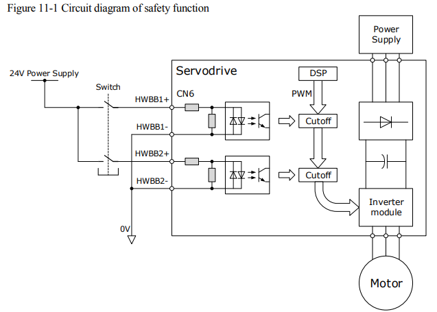
Close the Switch for turning ON HWBB1 and HWBB2, PWM signal can be allowed to pass by Cutoff circuit, which is, allowing the torque to output.
Open the Switch for turning OFF HWBB1 or HWBB2, PWM signal cannot be allowed to pass by Cutoff circuit, which is, forbidding the torque to output.
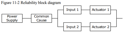
The reliability block diagram of safety function is as shown in Figure 11-2
Functions and Features
The functions or features of STO are as follows:
The safe state is the hardware shutdown of all PWMs, which make the Motor torque off.
The architecture of the system is 1oo1 + 1oo2.
The STO works in high demand mode of operation, and systematic capability is SC3.
The PFH may amount to 0.018% of the complete safety loop, and and it is 1.8*10-11
MTTFd of each channel is 3184 years.
According to IEC 61508-6: 2010, MRT and MTTR are both 0.
Failure rates are: λ (total failures) = 355.80 fit; λS (safe failures) = 283.38 fit;
λDD (dangerous detected failures) = 71.69 fit;
λDU (dangerous undetected failures) = 0.73 fit.
[NOTE] The unit for failure rates is 1 fit (failures in time) = 1*10-9 h -1 , meaning one failure in 109 operation hours of the device.
The safety integrity level is SIL3 (IEC 62061: 2015), the performance level is PLe, the category is Cat.4 (ISO 13849-1: 2015).
According to IEC 61508:2010 and IEC62061:2015, the SFF is no less than 99% for dual channel part (1oo2), and is no less than 99% for signal channel part (1oo1).
According to ISO 13849-1: 2015, DC is no less than 99%.
(*) The response time of STO is no more than 30ms.
Response time of STO is the time frame from the STO signal is triggered to the PWM signal is removed.
(*) The diagnose test interval is less than 20ms for HFT=0, and is less than 1h for HFT>0.
(*) According to IEC61326-3-1 for the DS definition, the Motor will stop within 200ms.
According to ISO 13849: 2015, the CCF score is better than 65.
(*) All detected faults will lead to safe state.
(*)In single channel, diagnostic test interval + fault reaction time < 30ms.
(*) Input signal filtering time definition: when the input signal keeps low level more than 2ms, turns HWBB1 and HWBB2 OFF and the system will enter safe state.

Risk Assessment
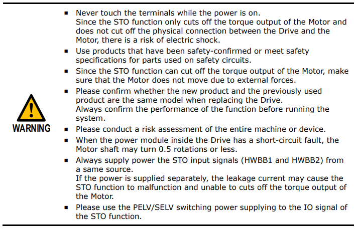
The device manufacturer is responsible for the residual risks associated with all risk assessments. The following are residual risks associated with STO functions. ESTUN is not responsible for any damage or injury caused by residual risks.
Alarms
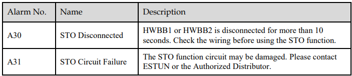
If A30 (STO Disconnected) alarm or A31 (STO Circuit Failure) alarm occurs in the Drive, which means that the STO function circuit may be damaged. The user should troubleshoot to use the STO function again.
Applicable Standards
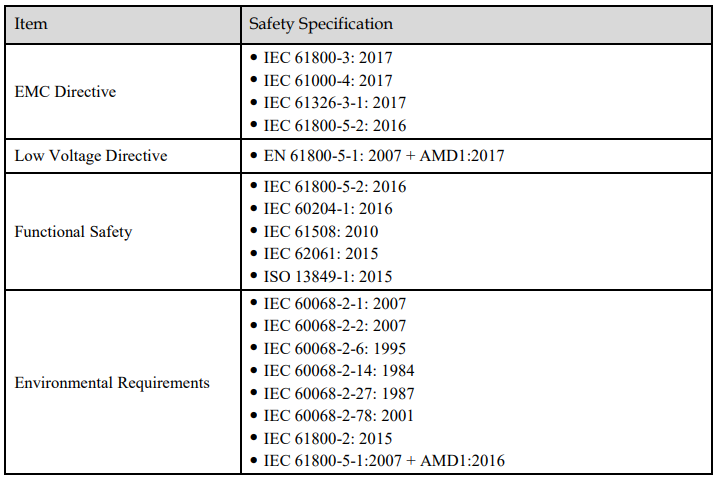
The safety standards followed by STO are shown in the table below.
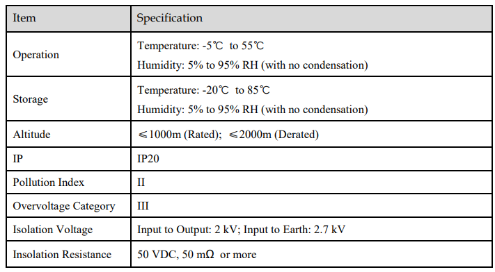
11.2 Environmental Conditions

11.3 Terminals Arrangement
Signal Diagram
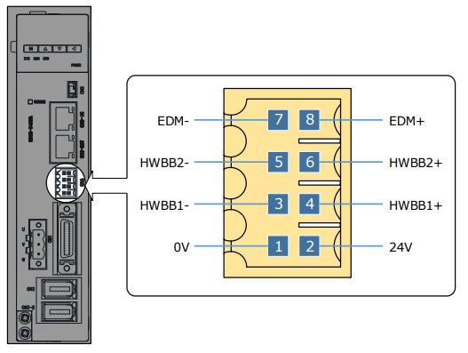
Pin Layout

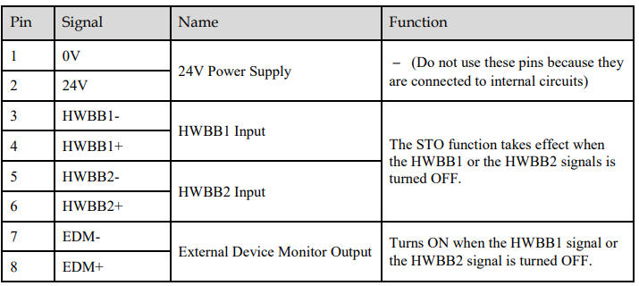
Signal Specifications
The input specifications of the HWBB1 signal (CN6-3, -4) and HWBB2 signal (CN6-5, -6) are as follows.

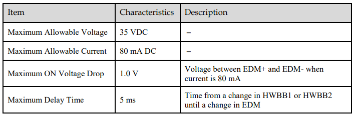
The electrical characteristics of the EDM (CN6-7, -8) output signal are as follows:
11.4 Function Description
11.4.1 EDM (External Device Monitor)
The EDM (External Device Monitor) signal is used to monitor failures in the STO. Connect the monitor signal as a feedback signal, e.g., to the Safety Function Device.
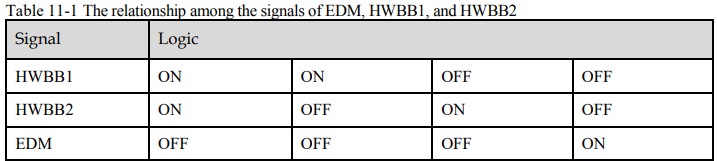
The relationship among the signals of EDM, HWBB1, and HWBB2 is shown in Table 11-1

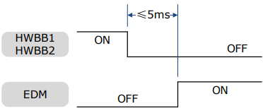
If an STO is requested by turning OFF input signals (HWBB1 and HWBB2) when the safety function is operating normally, the EDM output signal will be turned ON within 5 milliseconds.
11.4.2 Safe State
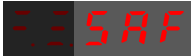
When the STO function takes effect, the Drive enters the safe state and the Panel Operator displays SAF, as is shown below.
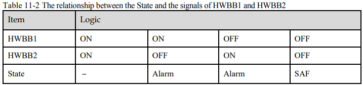
The relationship between the State and the signals of HWBB1 and HWBB2 is shown in Table 11-2
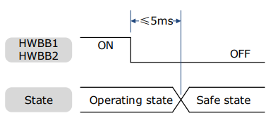
Turn OFF input signals (HWBB1 and HWBB2) for taking effect the STO function, the power supplied to the Motor will be cut off within 5 milliseconds.
Safety output signal from the safety controller and safety sensor may include L pulse for self-diagnosis. Make sure the off period of safety input signal less than 1 millisecond, and the safety input circuit does not detect this OFF event.

11.4.3 S-RDY (Servo Ready Output) Signal
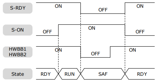
When the Drive is in Safe State, S-RDY (Servo Ready Output) signal is OFF.
When the HWBB1 and the HWBB2 signals are turned ON, and the Servo is OFF, the S-RDY signal will be turned ON, and the Drive will be in Ready State.
11.4.4 /BK (Brake Ouput) Signal
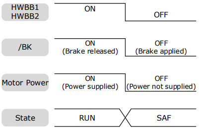
If the STO function takes effect when the HWBB1 or HWBB2 signal is OFF, the /BK (Brake) signal will turn OFF. At that time, the setting in Pn506 (Brake Reference-Servo OFF Delay Time) will be disabled.
11.4.5 Stopping Methods
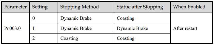
The Drive will enter the safe state when the STO function takes effect, and the Motor will stop according to the setting of Pn003.0.
11.4.6 Reset Method for Deviation Counter
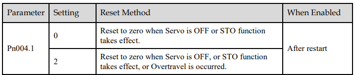
The Drive will enter the safe state when the STO function takes effect, and the Deviation Counter will reset according to the setting of Pn004.1.
11.5 Safety Function Device Connection
11.5.1 Disconnecting a Safety Function Device
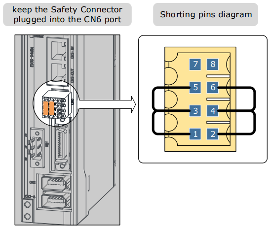
If you do not connect a safety function device, keep the Safety Connector plugged into the CN6 port, and the shorting pins on the connector remain in the default state.


11.5.2 Connecting a Safety Function Device
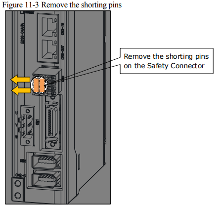
Remove the shorting pins on the Safety Connector
Remove the shorting pins on the Safety Connector as shown in Figure 11-3.
Wiring the Safety Function Device
Connect the Safety Function Device to the CN6 port according to the wiring example shown in Figure 11-4.
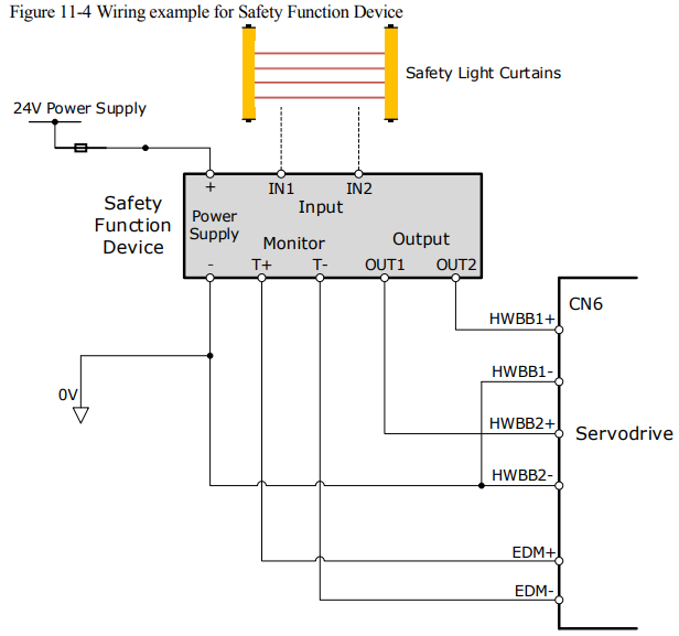
Use armored cables to protect the HWBB1+ and HWBB2+ from short circuits.
Use the EDM signal at the common emitter output, making sure that the current flows from EDM+ to EDM-.
When the safety grating is blocked, the HWBB1 and HWBB2 signals turn OFF, and the EDM signal is turned ON to enter the Safe State.
When the blocking of the safety grating is released, the HWBB1 and HWBB2 signals turn ON, and the Drive will enter the Operating State.
Validating Safety Functions
When you commission the system or perform maintenance or Drive replacement, you must always perform the following validation test on the STO function after completing the wiring. (It is recommended that you keep the confirmation results as a record.)
When the HWBB1 and HWBB2 signals turn OFF, confirm that the Panel Operator displays SAF and that the Motor does not operate.
Monitor the ON/OFF status of the HWBB1 and HWBB2 signals.
If the ON/OFF status of the signals do not coincide with the display (Un006), the following must be considered:
− An error in the external device.
− Disconnection of the external wiring, short-circuiting in the external wiring.
− A failure in the Drive.
Find the cause and correct the problem.
Troubleshooting
Any one of the input signal HWBB1 or HWBB2 turns OFF, the Drive will enter the Safe State. However, if other signal is still ON for more than 10 seconds, an alarm A30 (STO Disconnected) will occur. At that time, the following must be considered:
The circuit or device used to input the HWBB1 and HWBB2 signals may be faulty.
The cable for the input signal has been disconnected.
Find the cause and correct the problem.
11.6 Procedure
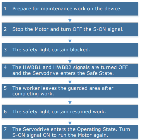
Taking the wiring of the Safety Function Device shown in Figure 11-4 as an example, use the STO function as follows.
No comments to display
No comments to display