
3. Wiring and Connecting
3.1 Precautions for Wiring
3.1.1 General Precautions

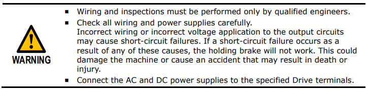
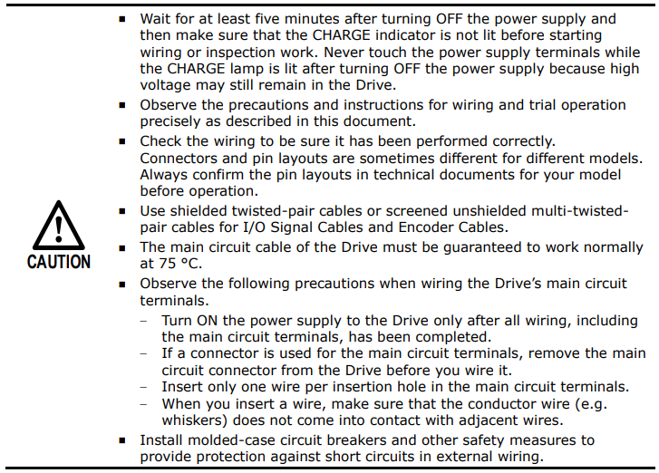
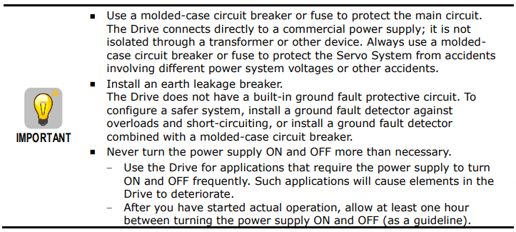
3.1.2 Countermeasures against Noise

Since the Drive uses microprocessors, it may be affected by switching noise from peripheral devices.
To prevent the noise from the Drive or the peripheral devices from causing malfunctions of any devices, take the following countermeasures against noise as required.
Install the input reference device and Noise Filter as close to the Drive as possible.
Always install a Surge Absorber for relays, solenoids, and Magnetic Contactor coils.
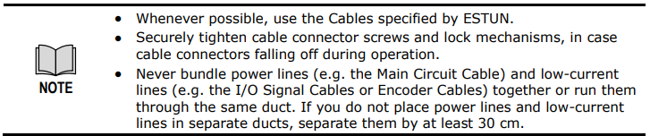
Never place the following cables in the same duct or bundle them together. Also, separate the cables from each other by at least 30 cm.
− Main Circuit Cables and I/O Signal Cables
− Main Circuit Cables and Encoder Cables
Never share the power supply with an electric welder or electrical discharge machine. If the Drive is placed near a high-frequency generator, install Noise Filters on the input side on the Main Circuit Power Supply Cable and Control Power Supply Cable even if the same power supply is not shared with the high-frequency generator. Refer to the section Noise Filters for information on connecting Noise Filters.
Implement suitable grounding measures. Refer to the section 3.1.3 Grounding for information on grounding measures.
Noise Filters
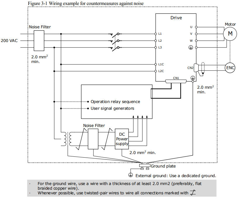
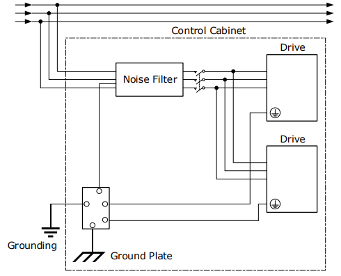
You must attach Noise Filters in appropriate places to protect the Drive from the adverse effects of noise. Figure 3-1 is an example of wiring for countermeasures against noise.
Noise Filter Wiring and Connection Precautions
Always observe the following precautions when wiring or connecting Noise Filters.
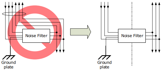
Separate input lines from output lines. Do not place input lines and output lines in the same duct or bundle them together.
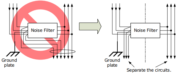
Separate the Noise Filter ground wire from the output lines. Do not place the Noise Filter ground wire, output lines, and other signal lines in the same duct or bundle them together.
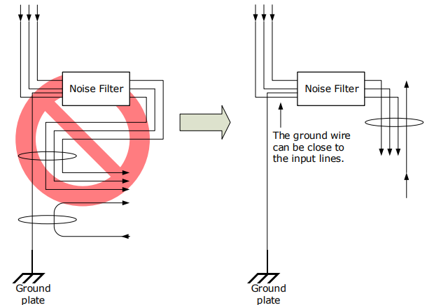
Connect the Noise Filter ground wire directly to the grounding plate. Do not connect the Noise Filter ground wire to other ground wires.
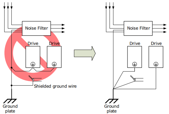
If a Noise Filter is located inside a control panel, first connect the Noise Filter ground wire and the ground wires from other devices inside the control panel to the grounding plate for the control panel, then ground the plate.
3.1.3 Grounding
Implement grounding measures as described in this section. Implementing suitable grounding measures will also help prevent malfunctions, which can be caused by noise.
Observe the following precautions when wiring the ground cable.
Ground the Drive to a resistance of 100 mΩ or less.
Be sure to ground at one point only.
Ground the Motor directly if the Motor is insulated from the machine.
Motor Frame Ground or Motor Ground
If you ground the Motor through the machine, switching noise current can flow from the main circuit of the Drive through the stray capacitance of the Motor. To prevent this, always connect the Motor frame terminal (FG) or ground terminal (FG) of the Motor to the ground terminal  on the Drive. Also be sure to ground the ground terminal
  .
.
Noise on I/O Signal Cables
If noise enters the I/O Signal Cable, connect the shield of the I/O Signal Cable to the connector shell to ground it. If the Motor Main Circuit Cable is placed in a metal conduit, ground the conduit and its junction box. For all grounding, ground at one point only.
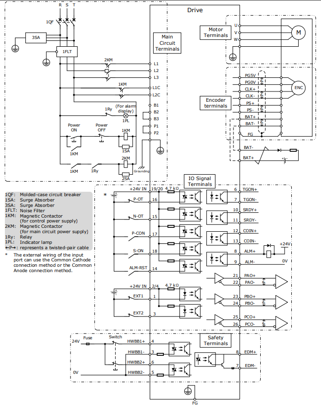
3.2 Basic Wiring Diagrams
3.3 Wiring the Power Supply to Drive
3.3.1 Terminals Arrangement
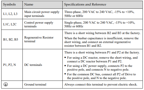
The power supply to Drive includes main circuit terminals and control circuit terminals.
Signal Diagram
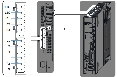
Pin Layout
3.3.2 Wiring Procedure
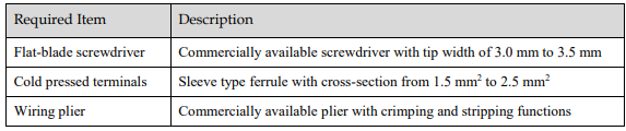
Prepare the following items before preparing the wiring for the Main Circuit Terminals and Control Circuit Terminals.
Follow the procedure below to wire the Main Circuit Terminals and Control Circuit Terminals.
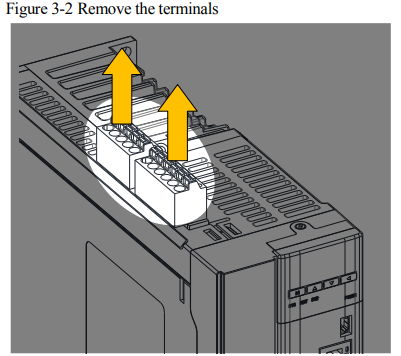
Step 1 Remove the Main Circuit Terminals and Control Circuit Terminals from the Drive.
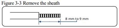
Step 2 Peel off the sheath so that the conductor portion of the cable will protrude from the tip of the ferrule.
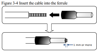
Step 3 Insert the cable into the ferrule (It should protrude 1 mm or more from the ferrule).
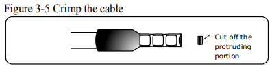
Step 4 Crimp the cable that has been inserted into the ferrule, and cut off the cable conductor portion protruding from the ferrule (The allowable protruding length after cutting should not be more than 0.5 mm).
Step 5 Insert the crimped cable into the connection terminals directly until the cable is not easily pulled out (A slight pull is allowed).
Step 6 Make all other connections in the same way.
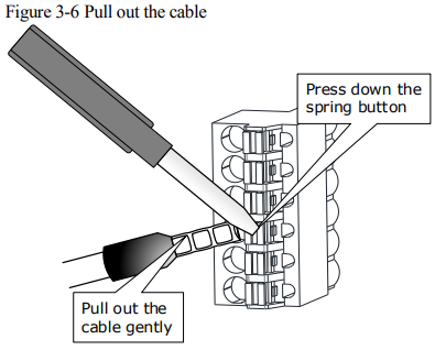
Step 7 To change the wiring, pull the cable out of the connection terminals.
Use the flat-blade screwdriver to press down the spring button corresponding to the terminal, and then gently pull out the cable.
Step 8 When you have completed wiring, attach connection terminals to the Drive.

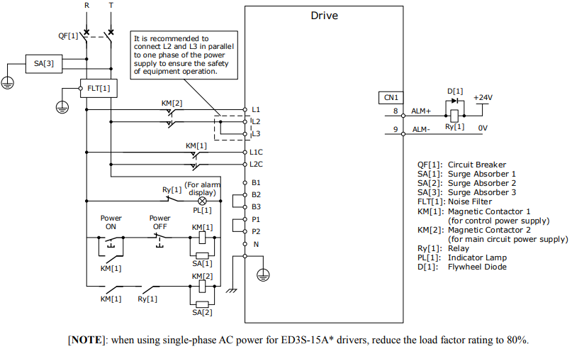
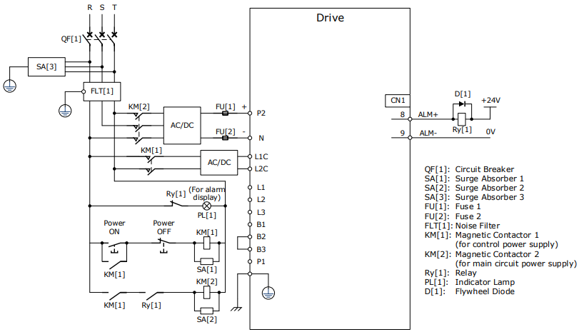
3.3.3 Wiring Diagrams
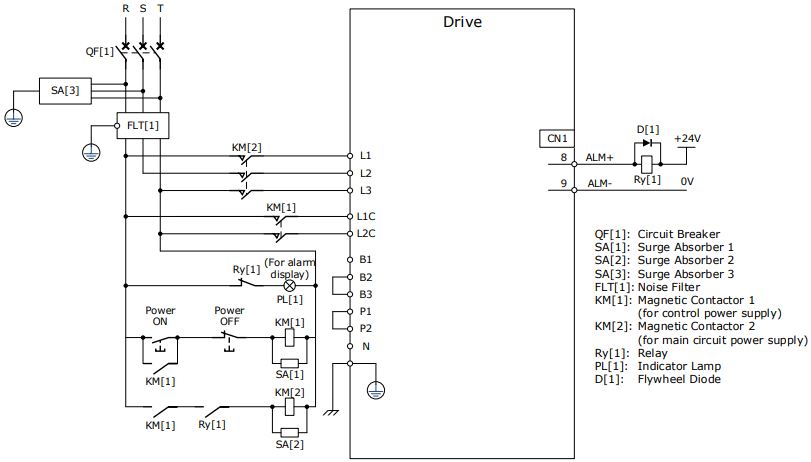
Wiring Example for Three-phase Power Supply Input
Wiring Example for Single-phase Power Supply Input
Wiring Example for DC Power Supply Input
3.4 Wiring the Motor
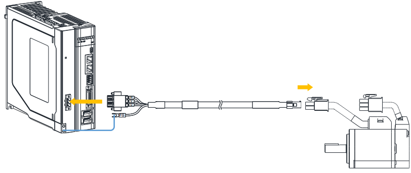
Connection Diagram
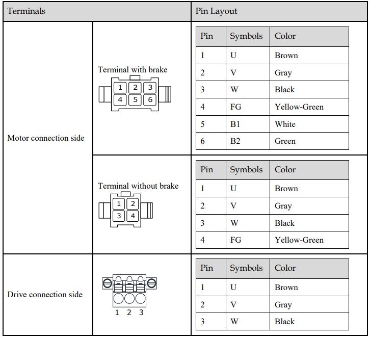
Terminals Arrangement
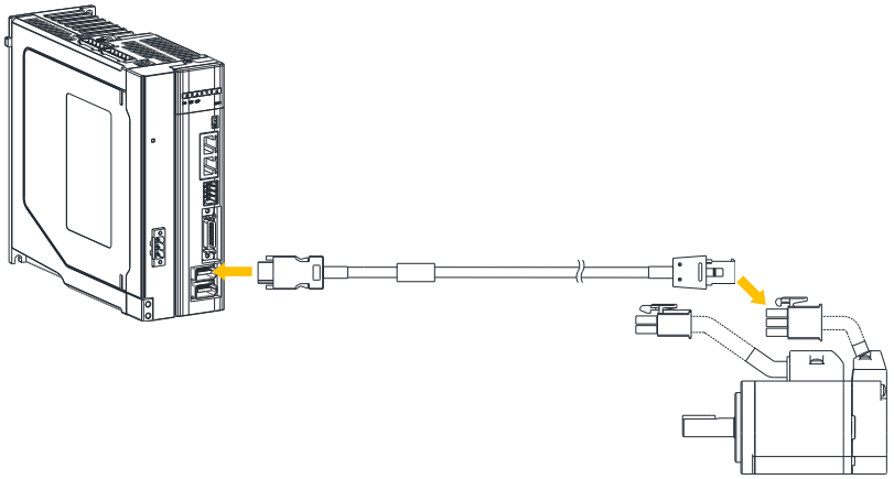
3.5 Wiring the Encoder
Connection Diagram
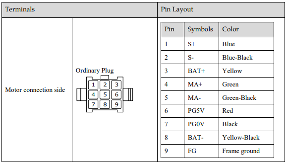
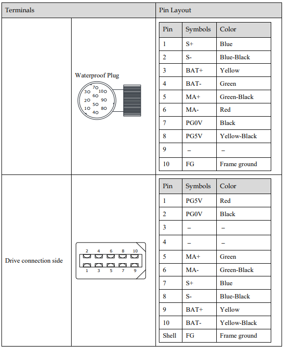
Terminals Arrangement
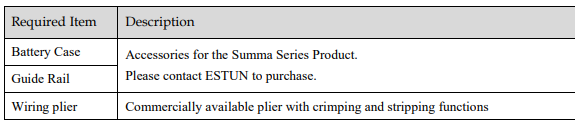
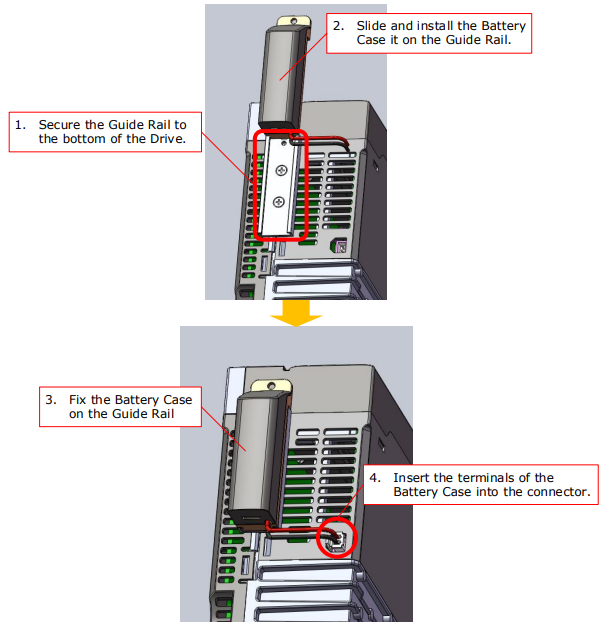
Battery Case Connection

Prepare the following items before connecting a Battery Case.
The installation diagram of the battery case is as follows.

3.6 I/O Signal Connections
Signal Diagram
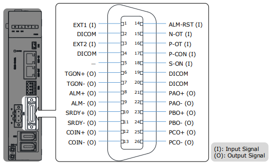
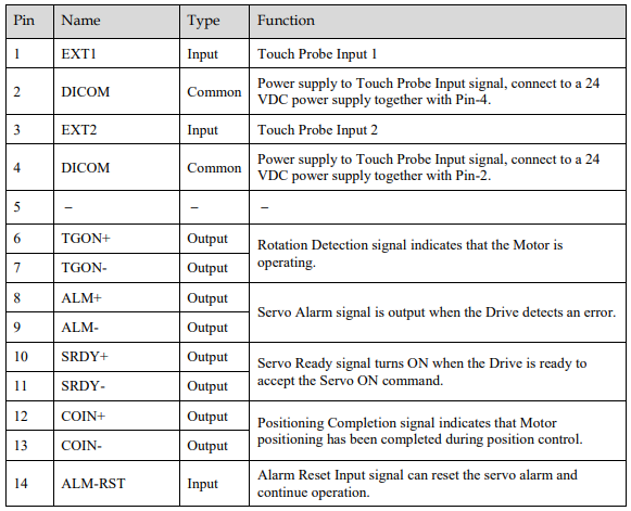
Pin Layout

3.7 Communication Connections
3.7.1 EtherCAT Communication Cable
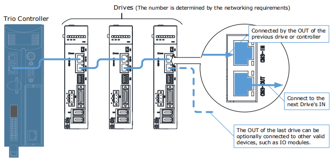
Connection Diagram
Pin Layout
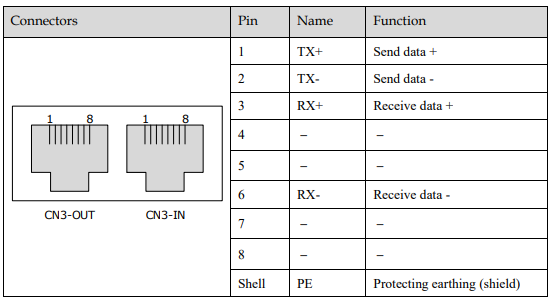
EtherCAT communication (CN3-ON and CN3-OUT) are RJ45 terminals. The communication cable as the master station or controller should be connected from CN3-IN, and CN3-OUT should be connected to the CN3-IN terminal of the next Drive (slave station).
Cable Description
You shall purchase or make your own EtherCAT communication cable.
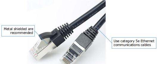
Use category 5e Ethernet communications cables to make the connections, and metal shielded terminals are recommended to prevent signal interference.
3.7.2 USB Communication Cable
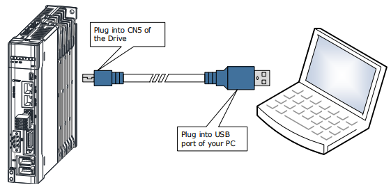
Connects your PC to a Drive with a USB Communication Cable, in order to make the online operation of ESView V4.
Connection Diagram
Cable Description
You can purchase the USB Communication Cable provided by ESTUN, or you can purchase the commercially available products yourself.
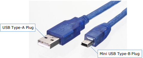
The plug connected to your PC is USB Type-A, and the plug connected to the Drive is Mini USB Type-B
3.8 Wiring the External Encoder
The External encoder will be used only with a fully-closed system. For the connection and usage, please refers to Chapter 10 Fully-Closed Loop Control.
Signal Diagram
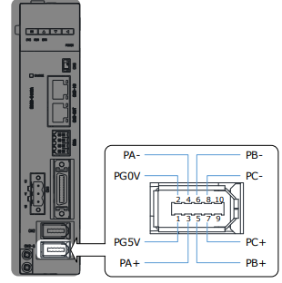
Pin Layout
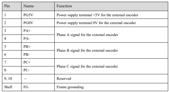
3.9 Connecting STO Function Signals
A Safety Function Device shall be connected for using the STO function. For the connection and usage, please refers to Chapter 11STO.
No comments to display
No comments to display