
4. Basic Settings
You can implement the functions of parameter setting, display, monitoring, alarm, adjustment, etc. of the Drive in the following two ways.
Use the Panel Operator of the Drive
Use the ESView V4 (Recommended)
4.1 Panel Operator
4.1.1 Key Names and Functions
There is a Panel Operator on the front of the Drive, as is shown in Figure 4-1.
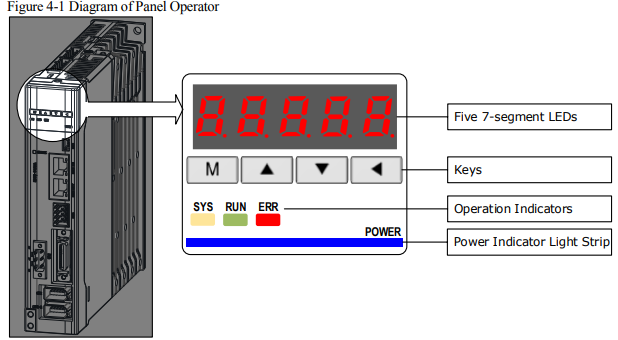
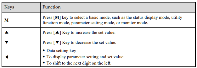
The names and functions of the keys on the Panel Operator are as follows
4.1.2 Basic Mode Selection
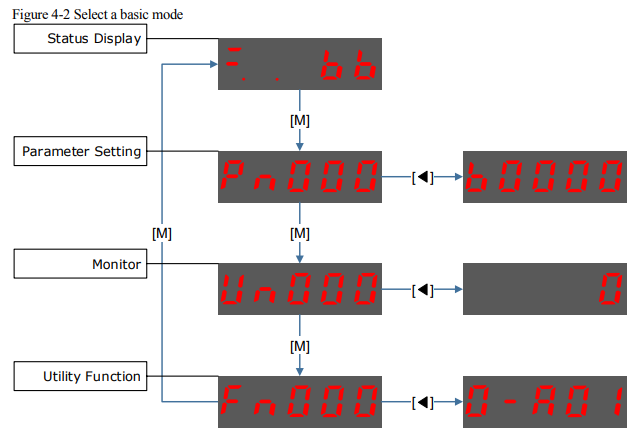
The basic modes include: Status Display Mode, Parameter Setting Mode, Utility Function Mode, and Monitor Mode. Select a basic mode with [M] key to display the operation status, set parameters and operation references, as is shown in Figure 4-2.
4.1.3 Status Display Mode
Power ON the Drive and wait for a while, the Panel Operator will initially display the Servo Status.
The information displayed by the status is divided into two parts:
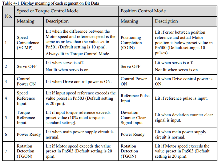
The first two digits are called Bit Data, what indicates the signal states during the operation of Drive.
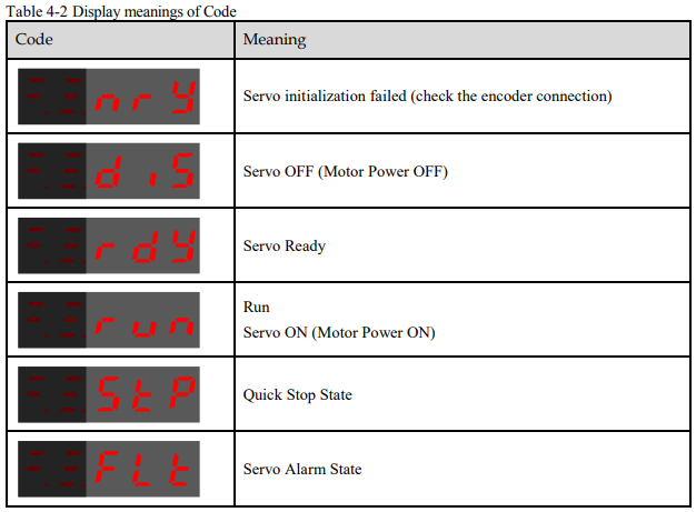
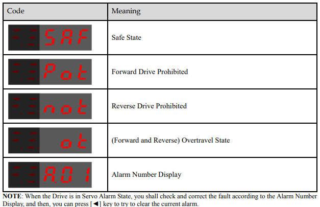
The last three digits are called Code, what indicates the operation states of Drive.
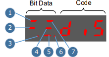
The display meaning of each segment on Bit Data are shown in Table 4-1, and they have different meanings under Speed or Torque Control Mode and Position Control Mode.
The display meanings of Code are shown in Table 4-2
4.1.4 Parameter Setting Mode
Functions can be selected or adjusted by setting parameters. There are two types of parameters.
Function Parameters: the functions allocated to each digit of the Panel Operator can be selected.
Adjustment Parameters: a parameter is set to a value within the specified range of the parameter.
For a description of the parameter settings, please refer to the section 12.1 Parameters Lists.
Function Parameters Setting
The example below shows how to change parameter Pn003 (Application Function Selections 3) from 0000 to 1032.
Step 1 Press [M] key several times to select the Parameter Setting Mode.
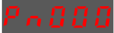
Step 2 Press [▲] key or [▼] key to select the parameter Pn003.
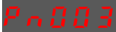
Step 3 Press [◄] key to display the current value of Pn003.
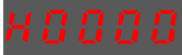
Step 4 Press and hold [◄] key for 1 second or more, and then a flashing decimal point will appear at the bottom right of the 5th digit.

Step 5 Press [▲] key twice, changing the value of the 5th digit from 0 to 2.
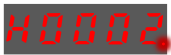
Step 6 Press [◄] key once, moving the flashing decimal point to the 4th digit
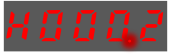
Step 7 Press [▲] key three times, changing the value of the 4th digit from 0 to 3.
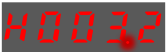
Step 8 Press [◄] key twice, moving the flashing decimal point to the 2nd digit.
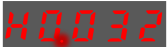
Step 9 Press [▲] key once, changing the value of the 2nd digit from 0 to 1.
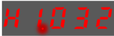
Step 10 Press and hold [◄] key for 1 second or more to return to the display of the Pn003 parameter value, or press the [M] key to return to the display of the Pn003.

Adjustment Parameters Setting
The example below shows how to change parameter Pn102 (Speed Loop Gain) from 100 to 85.
Step 1 Press [M] key several times to select the Parameter Setting Mode.
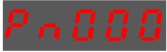
Step 2 Press [▲] key or [▼] key to select the parameter Pn102.
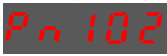
Step 3 Press [◄] key to display the current value of Pn102

Step 4 Press [▲] key or [▼] key to change the value to 00085.
Press and hold [▲] key or [▼] key to jump the setting value quickly.
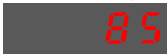
Step 5 Press [◄] key or [M] key to return to the display of Pn102.
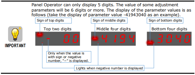
The example below shows how to change parameter Pn504 (Deviation Counter Overflow Alarm) from 41943040 to 42943240.
Step 1 Press [M] key several times to select the Parameter Setting Mode.
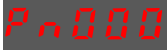
Step 2 Press [▲] key or [▼] key to select the parameter Pn504
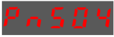
Step 3 Press [◄] key to display bottom four digits of the current value of Pn504.
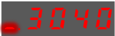
Step 4 Press and hold [◄] key for 1 second or more, and then a flashing decimal point will appear at the bottom right of the 5th digit.
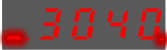
Step 5 Press [◄] key twice, moving the flashing decimal point to the 3rd digit
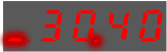
Step 6 Press [▲] key twice, changing the value of the 3rd digit from 0 to 2.

Step 7 Press [◄] key four times, moving the flashing decimal point to the 3rd of middle four digits.
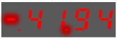
Step 8 Press [▲] key once, changing the value of the 3rd digit from 1 to 2.
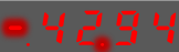
Step 9 Press and hold [◄] key for 1 second or more to return to the display of the Pn504 parameter value, or press the [M] key to return to the display of the Pn504.
4.1.5 Monitor Mode
The Monitor Mode can be used for monitoring the reference values, I/O signal status, and Drive internal status.
The Monitor Mode can be selected during Motor operation.
Select Monitor Mode
The example below shows how to display, the contents of monitor number Un000 (when the Motor rotates at 1500 rpm).
Step 1 Press [M] key several times to select the Monitor Mode.
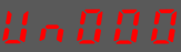
Step 2 Press [▲] key or [▼] key to select the monitor number Un000
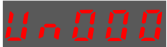
Step 3 Press [◄] key to display the data of Un000
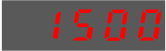
Step 4 Press [◄] key to return to the display of Un000.
Contents of Monitor Mode Display
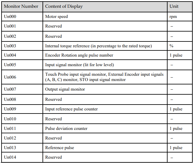
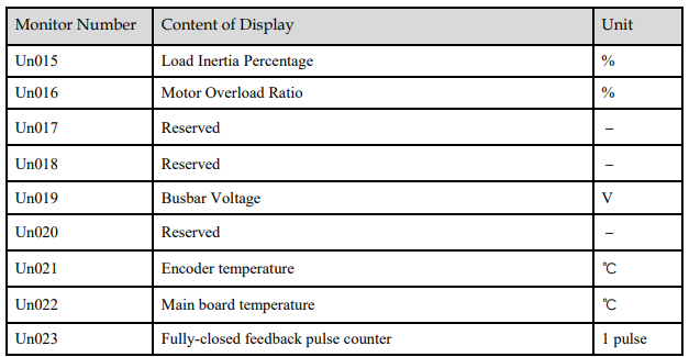
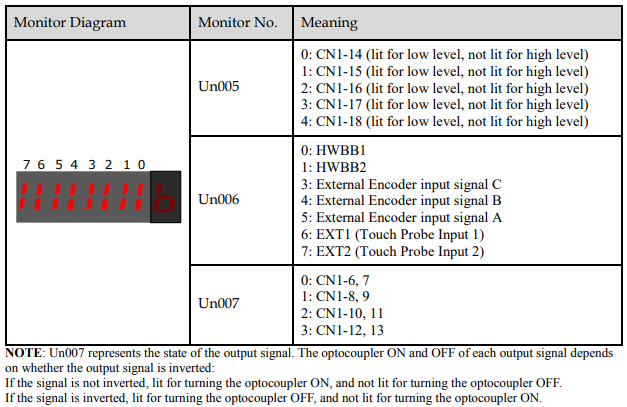
The status (low level or high level) of input signal allocated to each input terminal is displayed.
4.1.6 Utility Function Mode
This section describes how to apply the basic operations using the Panel Operator to run and adjust the Motor.
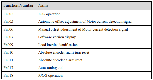
The following table shows the parameters in the Utility Function Mode.

Fn000 (Alarm trace data display)
The alarm trace data display can display up to ten previously occurred alarms. The following are the steps to display the alarm trace data.
Step 1 Press [M] key several times to select the Utility Function Mode.
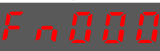
Step 2 Press [▲] key or [▼] key to select the function number Fn000.
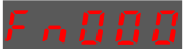
Step 3 Press [◄] key to display latest alarm number
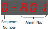
Step 4 Press [▲] key or [▼] key to view the other alarm data.
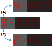
Step 5 Press the [◄] key to return to the display of the Fn000.
Press and hold [◄] key for 1 second or more to clear all the alarm trace data.
Fn001 (Initialize parameter settings)
The following are the steps to initialize parameter settings.
Step 1 Press [M] key several times to select the Utility Function Mode.

Step 2 Press [▲] key or [▼] key to select the function number Fn001.

Step 3 Press [◄] key, and Panel Operator displays as below.

Step 4 Press and hold [◄] key for 1 second to initialize the parameter settings, until Panel Operator displays and blinks done, which indicates the initialization of parameter setting has been completed.

Step 5 Release [◄] key to return to the display of the Fn001.
Fn002 (JOG operation)
This utility function often use used for trial operation, refers to the section 8.3.3 JOG Operation.
Fn005 (Automatic offset-adjustment of Motor current detection signal)
Motor current detection offset adjustment has performed at ESTUN before shipping. Basically, the user need not perform this adjustment.

The following are the steps to execute the automatic offset adjustment.
Step 1 Press [M] key several times to select the Utility Function Mode.

Step 2 Press [▲] key or [▼] key to select the function number Fn005.

Step 3 Press [◄] key, and Panel Operator displays as below.
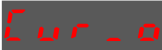
Step 4 Press [M] key to execute the automatic offset adjustment.
Panel Operator displays and blinks done, and 2 seconds later, it will return to previous display.
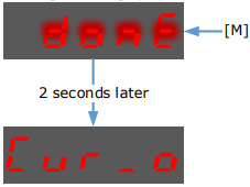
Step 5 Press the [◄] key to return to the display of the Fn005
Fn006 (Manual offset-adjustment of Motor current detection signal)
To adjust the offset, perform the automatic adjustment (Fn005) first. And if the torque ripple is still big after the automatic adjustment, perform the manual offset-adjustment as follow.

Step 1 Press [M] key several times to select the Utility Function Mode.
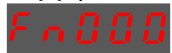
Step 2 Press [▲] key or [▼] key to select the function number Fn006.

Step 3 Press [◄] key, and Panel Operator displays as below.
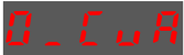
Step 4 Press [M] key for switching the display between 0_CuA (phase-U) and 1_Cub (phase-V).

Step 5 Select one phase display (e.g. 1_Cub, phase-V), and press and hold [◄] key for 1 second or more, Panel Operator will display the current offset value.

Step 6 Press [▲] key or [▼] key to change the offset value.
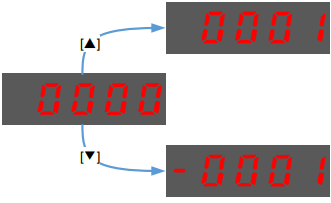
NOTE: the offset can be adjusted from -1024 to 1024.
Step 7 Press and hold [◄] key for 1 second or more to return to the phase display.
Step 8 Press [◄] key to return to the display of the Fn006.
Fn007 (Software version display)
The following are the steps to display the software versions.
Step 1 Press [M] key several times to select the Utility Function Mode.
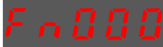
Step 2 Press [▲] key or [▼] key to select the function number Fn007.
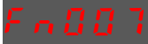
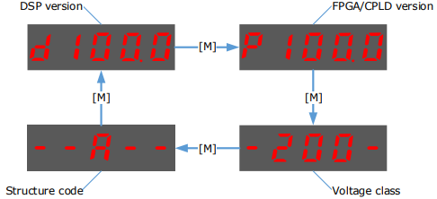
Step 3 Press [◄] key to display the software versions.
Step 4 Press [M] key serval time to display between DSP version, FPGA/CPLD version, Voltage class and Structure code.
Step 5 Press [◄] key to return to the display of the Fn007.
Fn009 (Load inertia identification)
This utility function often use used for tuning, refers to the section 9.7.1 Load Inertia Identification.
Fn010 (Absolute encoder multi-turn reset)
The following are the steps to reset the absolute encoder multi-turn data.
Step 1 Press [M] key several times to select the Utility Function Mode.
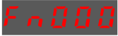
Step 2 Press [▲] key or [▼] key to select the function number Fn010

Step 3 Press [◄] key, and Panel Operator displays as below

Step 4 Press [M] key to reset the absolute encoder multi-turn data.

Step 5 Press [◄] key to return to the display of the Fn010.
Fn011 (Absolute encoder alarm reset)
The following are the steps to reset the absolute encoder alarm.
Step 1 Press [M] key several times to select the Utility Function Mode.
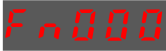
Step 2 Press [▲] key or [▼] key to select the function number Fn011.

Step 3 Press [◄] key, and Panel Operator displays as below.

Step 4 Press [M] key to reset the absolute encoder multi-turn data.

Step 5 Press [◄] key to return to the display of the Fn011.
Fn017 (Auto-tuning tool)
This utility function often use used for tuning, refers to the section 9.3.1 Auto-Tuning Tool.
Fn018 (PJOG operation)
This utility function often use used for trial operation, refers to the section 8.5 Program Jogging
4.2 ESView V4
4.2.1 Installation
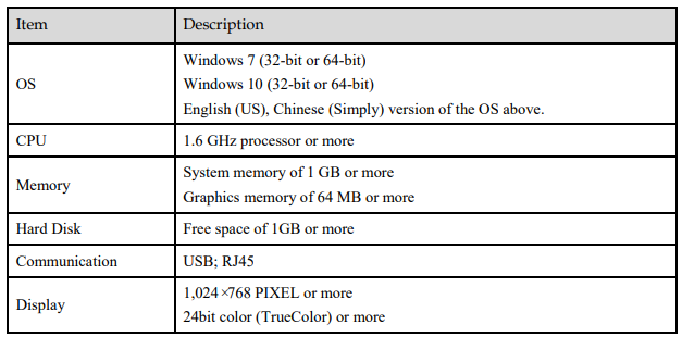
System Requirements
You need to provide for your own personal computer that meets the following basic hardware requirements.
Preparation
Please prepare the Windows operating system, communication cable, and a decompression software in advance.
Visit ESTUN official website www.estun.com to find and download ESView V4 on Technical Support > Download for getting the compressed file. For help, please contact ESTUN.
Turn on the power supply of PC and start Windows. (Close down other software running.)
Copy ESView V4 compressed file into an appropriate folder.
Disconnect if the Drive is connected to the PC with the cable.
Install Software
Close other running software before installing the software and confirm that the Windows user has administrator privileges.
Step 1 Extract the ESView V4 compressed file in an appropriate directory of your PC.
Step 2 Double click the ESView V4 installation program.
The installation program will automatically start, as shown in the Figure 4-3.
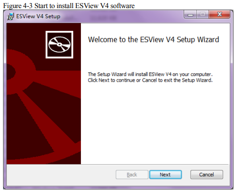
Step 3 Follow the instructions of the installation wizard to install ESView V4 to your PC.
Install USB Driver
After installing the ESView V4 software successfully, you may also need to install the USB driver. If you have successfully installed a USB drive, you can skip what is described in this section, otherwise follow the steps below to install the USB driver.

Step 1 After installing the ESView V4 software successfully, connect the Drive to the PC by using the USB connection cable.
Step 2 Open the main directory of ESView V4 software (default location is C:\ESView V4\), and extract the USB Drivers.rar compressed file to an appropriate directory of your PC.
Step 3 Open Device Manager.
For Win7 OS, select Start > Control Panel.
Click Device Manager on the displayed All Control Panel Items.
For Win10 OS, just right-click Start, and select Device Manager on the pop-up menu.
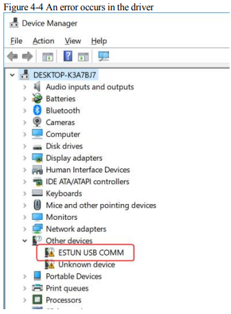
Step 4 An exclamatory mark attaches to the option Other devices > ESTUN USB COMM in Device Manager window, which indicates an error occurs in the driver and needs to update, as shown in Figure 4-4.
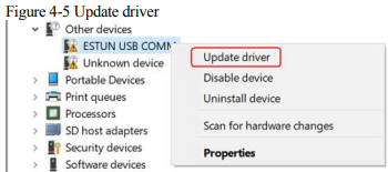
Step 5 Right-click ESTUN USB COMM, and select Update driver on the pop-up menu.
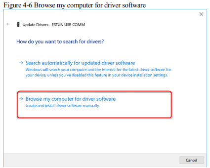
Step 6 Click Browse my computer for driver software on the Update Drivers dialog box
Step 7 Click Let me pick from a list of available drivers on my computer.

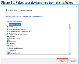
Step 8 Click Next
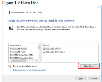
Step 9 Click Have Disk.
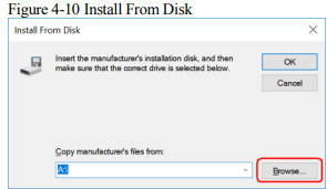
Step 10 Click Browse on the Install From Disk dialog box
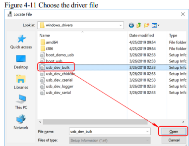
Step 11 Set the Look in as the directory of ESView V4 decompressed file \USB Drivers\windows_drivers on the Locate File dialog box.
Step 12 Choose usb_dev_bulk.inf, and then click Open.
Step 13 Click OK on the Install From Disk dialog box.
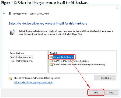
Step 14 Choose Generic Bulk Device, and then click Next.
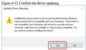
Step 15 Click Yes on the Update Driver Warning dialog box
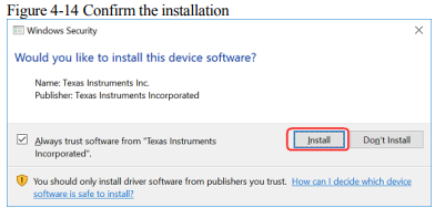
Step 16 Wait for a while, and then click Install on the Windows Security dialog box.
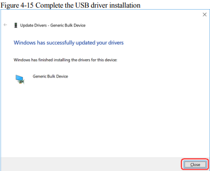
Step 17 The driver will be automatically installed to your PC, and then the installation result will be displayed. Click Close to complete the USB driver installation.
4.2.2 Starting ESView V4
Online Operation
The parameters only can be written into or read from the Drive under the online operation. It is recommended that you perform an online operation for the first time to set the Drive.
You need to connect the Drive to the PC by using the USB connection cable before the online operation.
Step 1 Connect the Drive to the PC by using the USB connection cable.
Step 2 Select Programs > ESView V4 > ESView V4 from the Windows Start Menu.
Also, you can find and click ESView V4 shortcut on the desktop of Windows.
Step 3 The Connect dialog box will be displayed.
If you had started ESView V4, select Home > Connect in the Menu Bar.
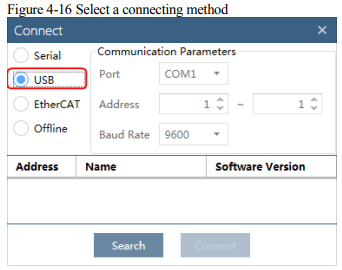
Step 4 Select USB.
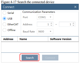
Step 5 Click Search.
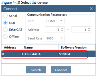
Step 6 Select the found device
Step 7 Click Connect
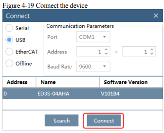
Step 8 The connected device will be displayed in the Device list on the left of the ESView V4 main windows.
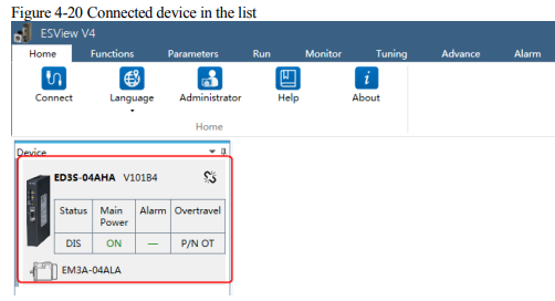
Now, you can make the necessary settings for the Drive or Motor in real time.

Offline Operation
You shall choose a Drive to manipulate on the computer under the offline operation. Since there is no online connection to a Drive, the functions that you can use are restricted.
Step 1 Select Programs > ESView V4 > ESView V4 from the Windows Start Menu.
Also, you can find and click ESView V4 shortcut on the desktop of Windows.
Step 2 The Connect dialog box will be displayed.
If you had started ESView V4, select Home > Connect in the Menu Bar.
Step 3 Select USB.
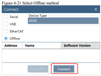
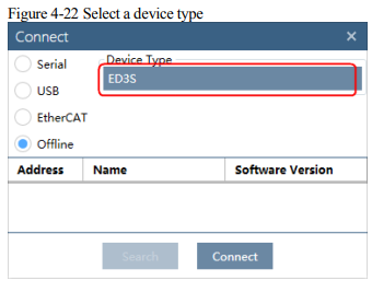
Step 4 Select the desired Device Type, e.g. ED3S
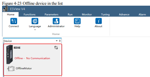
Step 5 The created device will be displayed in the Device list on the left of the ESView V4 main windows.

4.2.3 Edit Parameters
You can fulfill the following functions in Edit Parameters window.
Upload Parameters
Modify Parameters
Search Parameters
Download Parameters
Restore Parameters
Save Parameters
Follow the below procedure to open the Edit Parameters window.
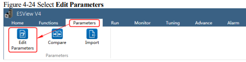
Step 1 Select Parameters > Edit Parameters in the Menu Bar of the ESView V4 main windows.
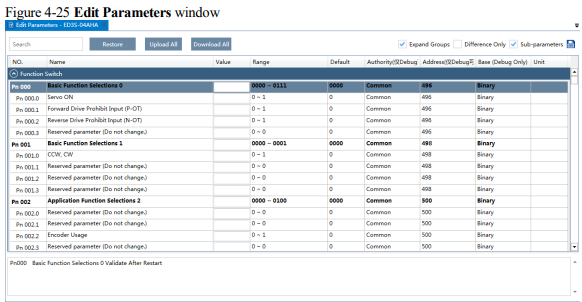
Step 2 The Edit Parameters window will be displayed in Function Display Area.
Upload Parameters
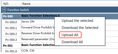
Upload All
In order to read all parameters from the Drive and fill them into Value column of the parameters list, you can:
− Click Upload All in the Edit Parameters window.

− Right-click the parameters list where cannot be edited, and select Upload All in the pop-up menu.
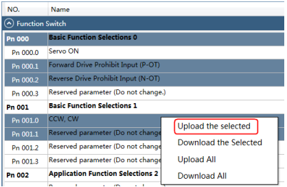
Upload the Selected
Drag the mouse to select the desired parameters, or you can hold Ctrl key and click the desired parameter, and then right-click a selected parameter, and select Upload the selected in the pop-up menu.

Modify Parameters
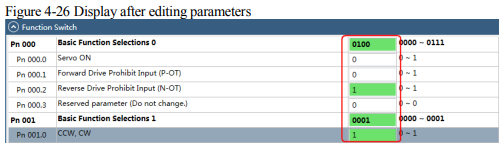
When the parameters have been uploaded from the device, you can modify them on the Value column. If a value has been modified, the background of the textbox can be changed, as shown in Figure 4-26.
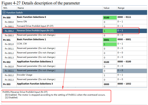
You can refer to the description displayed on the underside of the parameter list for the parameter modification.
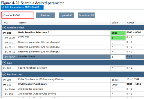
Search Parameters
Click Search input box on the Edit Parameters window, and type the keyword you want to search. The keyword, including NO, Name, Value, Range, Default, Unit, as well as description of each parameter. In order to search multiple items at once, add one or more space between keywords that lists all the parameters that match any of the keywords.
Download Parameters
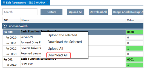
Download All
In order to write all parameters of the parameters list into the Drive, you can:
− Click Download All in the Edit Parameters window
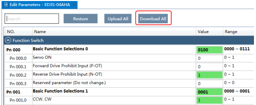
− Right-click the parameters list where cannot be edited, and select Download All in the pop-up menu.
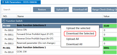
Download the Selected
Drag the mouse to select the desired parameters, or you can hold Ctrl key and click the desired parameter, and then right-click a selected parameter, and select Download the Selected in the pop-up menu.

Restore Parameters

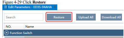
Step 1 Click Restore in the Edit Parameters window.
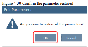
Step 2 Read the content on the warning dialog box and click OK
Step 3 ESView V4 will send the Restore Parameters command to the Drive, and then the Drive will execute the Restore Parameters.
Save Parameters
Follow the below procedure to save the current settings as an offline file into the PC.
Step 1 Click  in the Edit Parameters window.

Step 2 Choose the desired files in the Save As dialog box.
Step 3 Click Save.
4.2.4 Monitor
Device Status
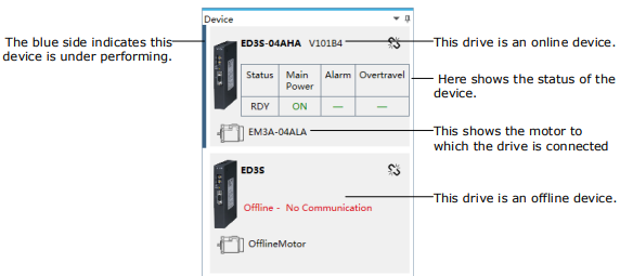
The Device list can display all the device you had connected or created (including online and offline), and their basic status.
IO Monitor
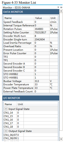
Use the Monitor function for displaying the main parameters of the device and the I/O signal information.
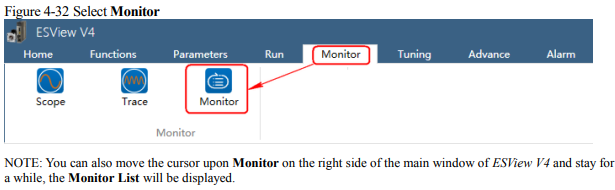
Step 1 Select Monitor > Monitor in the Menu Bar of the ESView V4 main windows.
Step 2 The Monitor List will display the information of DATA MONITOR and I/O MONITOR
No comments to display
No comments to display