
6. CiA402 Drive Profile
6.1 Conversion Factor Setting
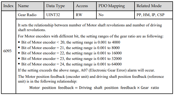
Gear Ratio (6093h)
The gear ratio indicates the Motor displacement (in encoder unit) corresponding to the driving shaft displacement of one reference unit.
The gear ratio is defined by the numerator (6091-01h) and denominator (6091-02h). It determines the relationship between the driving shaft displacement (in reference unit) and the Motor displacement (in encoder unit):

The Motor is connected with the load through the reduction wheel and other mechanical transmission mechanism. The gear ratio is calculated based on parameters such as the mechanical reduction ratio, mechanical size and Motor resolutions:




The resolutions of the Motor encoder with different bit are as follows:
The general incremental encoder outputs 10,000 pulses per 1 revolution
The resolver outputs 65536 pulses per 1 revolution
The 17-bit encoder outputs 131072 pulses per 1 revolution
The 20-bit encoder outputs 1048576 pulses per 1 revolution
The 23-bit encoder outputs 8388608 pulses per 1 revolution
Setting Example
Take the load ball screw as an example: Minimum reference unit fc=1 mm, Lead pB=10 mm/r, Reduction ratio n=5:1, 20-bit incremental encoder resolution P=1048576;
The gear ratio is calculated as follows:

Therefore, 6093-01h=524288, 6093-01h=1, which means that when the driving shaft displacement is 1, the Motor displacement is 524288.

6.2 Device Control
6.2.1 CiA402 State Machine
The Drive runs in the specified status only when it is instructed according to the flowchart defined in CiA402.
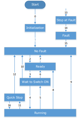
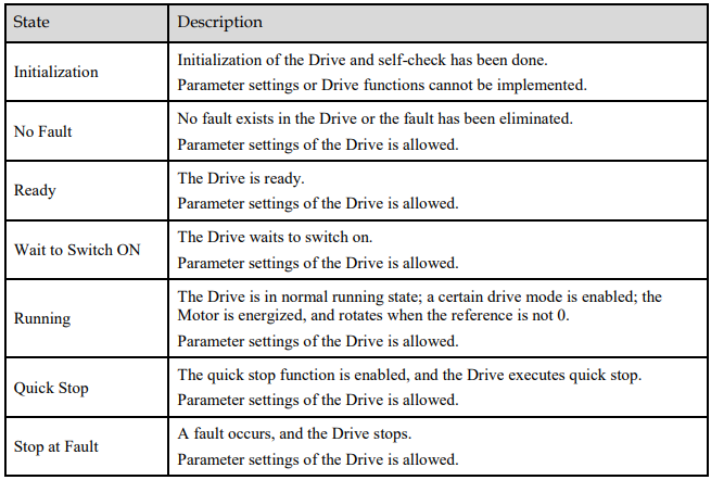
The states are described in the following table.

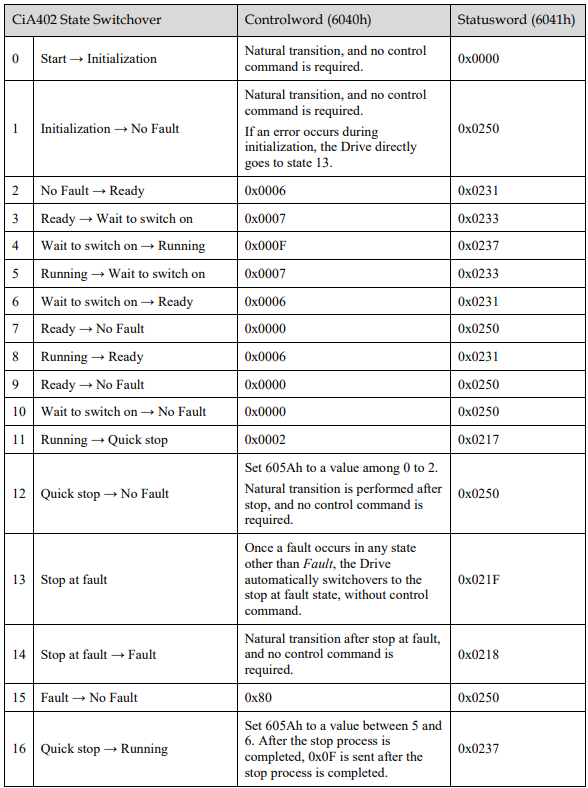
The control commands and state switchover are described as follows:
6.2.2 Stop Modes
The Drive supports 5 stop modes described as below sections.
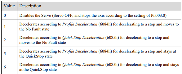
Quick Stop Option Code (605Ah)
This object determines what operation will be performed if a Quick Stop is executed

The meanings of Value are as follows:
605Bh (Shutdown Option Code)
This object defines the operation that is performed if there is a move from Operation Enable state to Ready state.

605Ch: Disable Operation Option Code
This object defines the operation that is performed if there is a move from Operation Enable state to Switched ON state.

The meanings of Value are as follows:

605Dh: Halt Option Code
This object defines the operation that is performed if bit 8 (Halt) in Controlword is active.

The meanings of Value are as follows:

605Eh: Fault Reaction Option Code
This object defines the operation that is performed when an alarm is detected in the Servo System.

The meaning of Value is as follows:

6.3 Control Modes
The Drive supports 8 control modes as defined in 6502h.

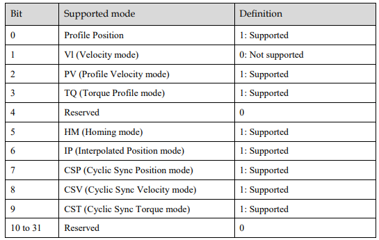
6.3.1 Modes of Operation
This object is used to select the operation mode. The Servo System gives the actual operation mode in the Modes of Operation Display object.

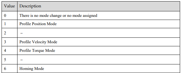
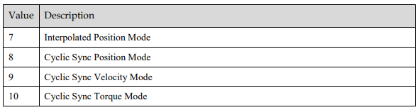
6.3.2 Modes of Operation Display
This object gives the current mode of operation.

6.3.3 Mode Change
Note the following when changing the control mode.
After changing from Position Control Mode (PP mode or CSP mode) to other modes, the unexecuted position command will be discarded.
A ramp stop command is executed when changing from Speed Control Mode (PV mode or CSV mode) or Torque Control Mode (PT mode or CST mode) to other modes. And then, changes to other modes after the stop has been completed.
It cannot be changed to other modes when the Servo is operating in the Homing Mode, except that the homing operation has been completed or interrupted (Fault or disabled).
Servo running status, after changing from other modes to CSP mode, CSV mode or CST mode, please send the command at least 1ms interval to avoid loss of instruction or error.
After changing the modes to Cyclic Sync Mode (CSP mode, CSV mode or CST mode), please wait 1 ms or more before sending the commands, in case losing command loss or error occurred.
6.3.4 Communication Cycle
The communication Cycle Time of all Control Modes (PP, PV, PT, HM, IP, CSP, CSV, and CST) supports an integer multiple of 125μs (e.g. 125μs, 250μs, 500μs, 1ms, and so on).
6.4 Position Control
6.4.1 Profile Position (PP) Mode
In this mode of operation, the host control uses the trajectory generator (an operation profile calculation function) inside the Drive to perform PTP positioning operation. It executes trajectory generator, position control, speed control, and torque control based on the target position, profile velocity, profile acceleration, profile deceleration, and other information.
Block Diagram
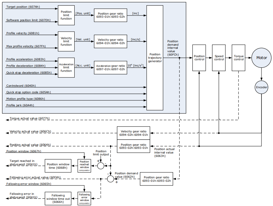
Speed Limit
The speed limit is determined by the smaller of 6080h value and 607F value
Relevant Objects
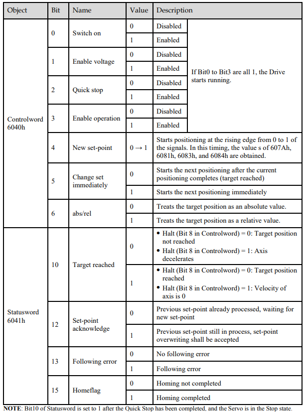

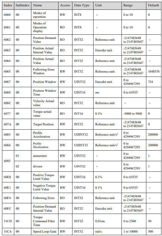
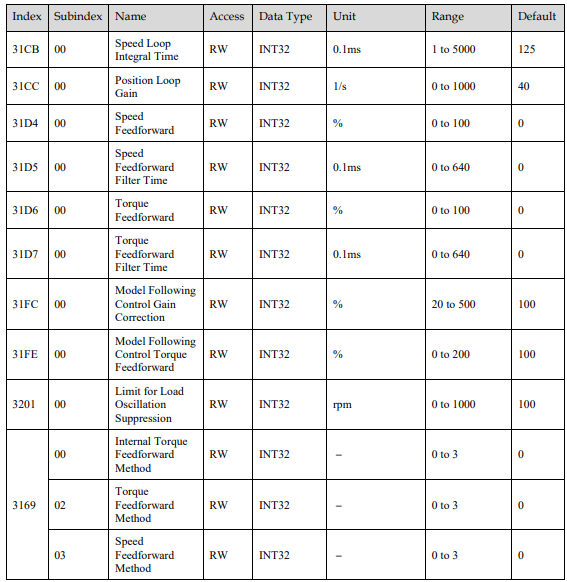
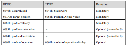
Recommended Configuration
6.4.2 Interpolated Position (IP) Mode
The Interpolated Position Mode is used to control multiple coordinated axes or to control a single axis that requires time interpolation of the set point data.
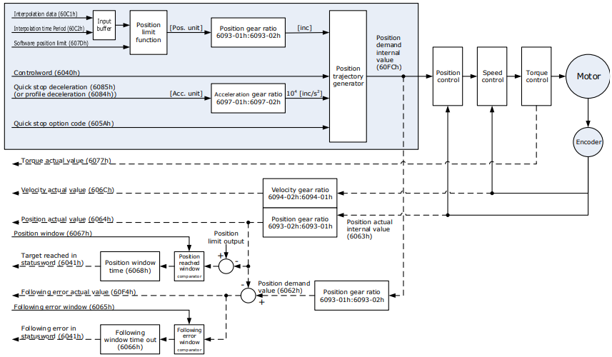
This mode normally uses a time (communications) synchronization mechanism to synchronize the Servo Drives. The Interpolation Time Period defines the update cycle of the Interpolation Data (i.e., the interpolation position). The interpolation processing in the Drive is based on this setting. The Interpolation Data is interpreted as an absolute value.
Block Diagram
Speed Limit
The speed limit is determined by the smaller of 6080h value and 607F value.
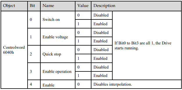
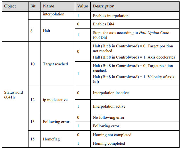
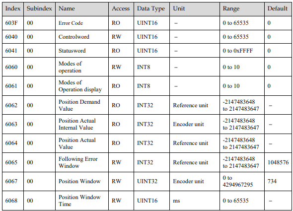
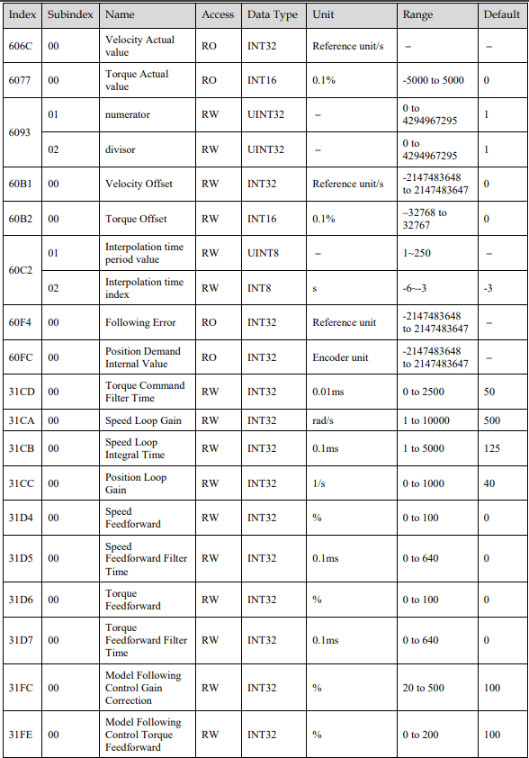
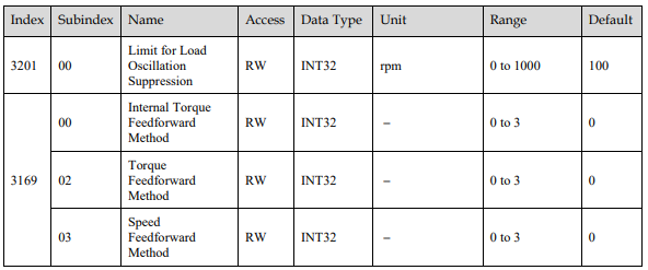
Relevant Objects
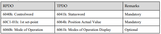
Recommended Configuration
6.4.3 Cyclic Synchronous Position (CSP) Mode
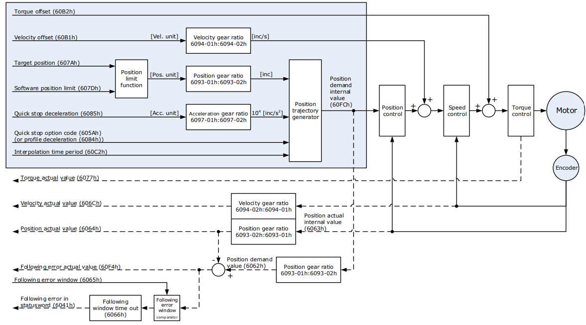
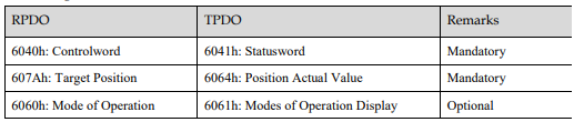
In this mode of operation, the host controller generates the position references and gives the target position in 607Ah to the Drive using cyclic synchronization. Position control, speed control, and torque control are performed by the Drive.
Block Diagram
Speed Limit
The speed limit is determined by the smaller of 6080h value and 607F value.
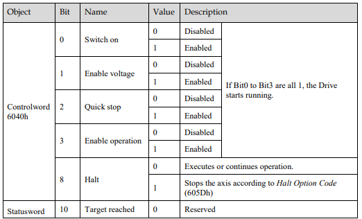
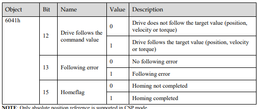
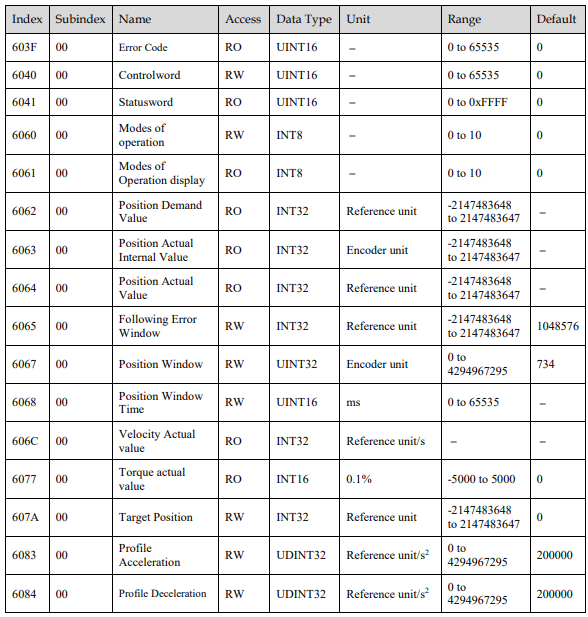
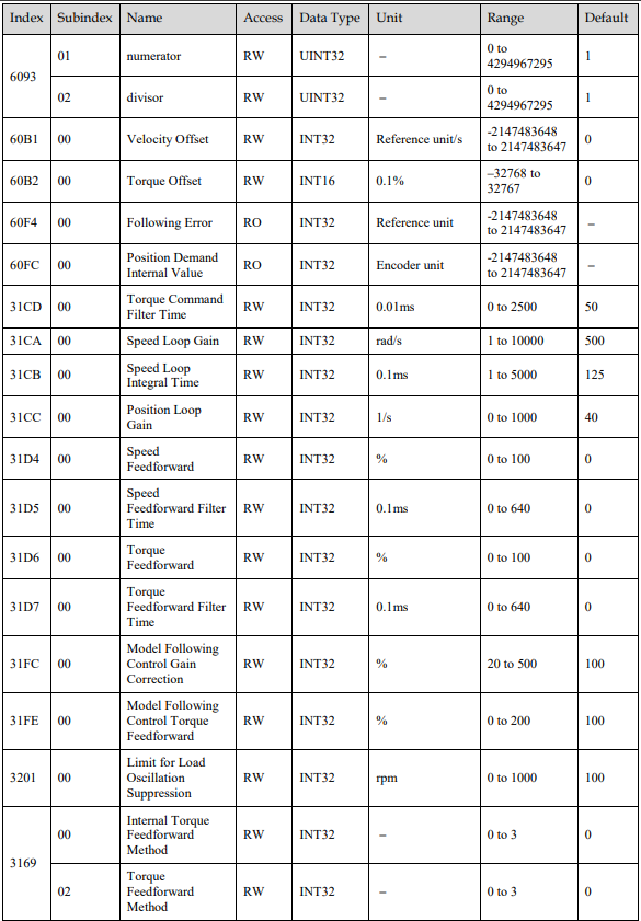
Relevant Objects

Recommended Configuration
6.5 Homing
6.5.1 Homing (HM) Mode
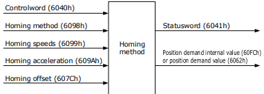
This mode searches for the home and determines the position relationship between home and zero.
Home: mechanical home reference point, that is, the encoder C-pulse.
Zero: absolute zero point in the machine.
After homing is completed, the Motor stops at the home. The relationship between home and zero is set in 607Ch.

When 607Ch=0, the zero is the same as the home.
Block Diagram
Speed Limit
The speed limit is determined by the smaller of 6080h value and 607F value.
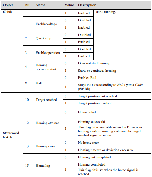
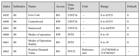
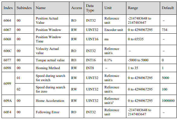
Relevant Objects

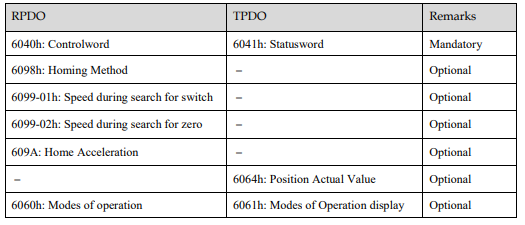
Recommended Configuration
6.5.2 Homing Methods

6098h = 1
Home: the Motor C-pulse signal
Deceleration point: negative limit switch (N-OT)
Deceleration point signal inactive at homing start:
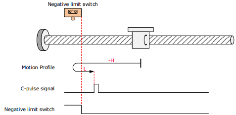
The N-OT signal is inactive initially, and the Motor starts homing in negative direction at high speed. After reaching the rising edge of the N-OT signal, the Motor decelerates and changes to run in positive direction at low speed.
After reaching the falling edge of the N-OT signal, the Motor stops at the first Motor C-pulse signal.
Deceleration point signal active at homing start
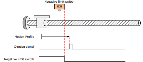
The N-OT signal is active initially, and the Motor directly starts homing in positive direction at low speed.
After reaching the falling edge of the N-OT signal, the Motor stops at the first Motor C-pulse signal.
6098h = 2
Home: the Motor C-pulse signal
Deceleration point: positive limit switch (P-OT)
Deceleration point signal inactive at homing start
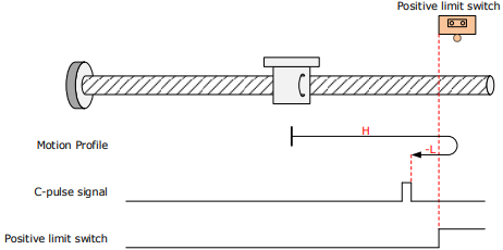
The P-OT signal is inactive initially, and the Motor starts homing in positive direction at high speed. After reaching the rising edge of the P-OT signal, the Motor decelerates and changes to run in negative direction at low speed.
After reaching the falling edge of the P-OT signal, the Motor stops at the first Motor C-pulse signal.
Deceleration point signal active at homing start
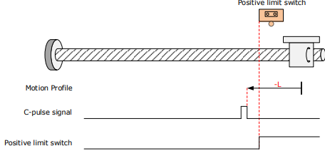
The P-OT signal is active initially, and the Motor directly starts homing in negative direction at low speed.
After reaching the falling edge of the P-OT signal, the Motor stops at the first Motor C-pulse signal.
6098h = 3
Home: the Motor C-pulse signal
Deceleration point: home switch (HmRef)
Deceleration point signal inactive at homing start:
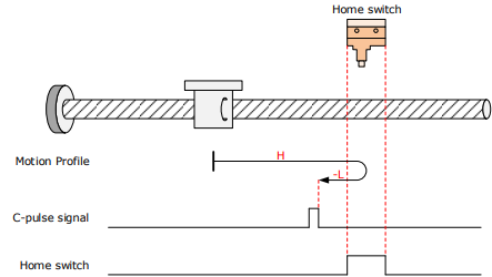
The HmRef signal is inactive initially, and the Motor starts homing in positive direction at high speed. After reaching the rising edge of the HmRef signal, the Motor decelerates and changes to run in negative direction at low speed.
After reaching the falling edge of the Hmref signal, the Motor stops at the first Motor C-pulse signal.
Deceleration point signal active at homing start:
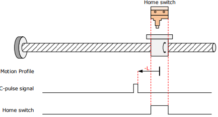
The HmRef signal is active initially, and the Motor directly starts homing in negative direction at low speed.
After reaching the falling edge of the HmRef signal, the Motor stops at the first Motor C-pulse signal.
6098h = 4
Home: the Motor C-pulse signal
Deceleration point: home switch (HmRef)
Deceleration point signal inactive at homing start:
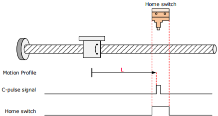
The HmRef signal is inactive initially, and the Motor directly starts homing in positive direction at low speed.
After reaching the rising edge of the HmRef signal, the Motor stops at the first Motor C-pulse signal.
Deceleration point signal active at homing start:
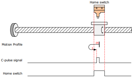
The HmRef signal is active initially, and the Motor starts homing in negative direction at high speed. After reaching the falling edge of the HmRef signal, the Motor decelerates and changes to run in negative direction at low speed.
After reaching the rising edge of the HmRef signal, the Motor stops at the first Motor C-pulse signal.
6098h = 5
Home: the Motor C-pulse signal
Deceleration point: home switch (HmRef)
Deceleration point signal inactive at homing start:
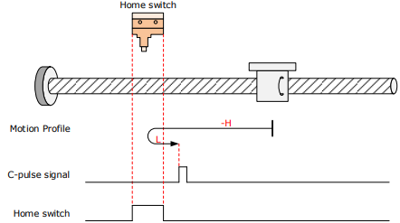
The HmRef signal is inactive initially. The Motor starts homing in negative direction at high speed. After reaching the rising edge of the HmRef signal, the Motor decelerates and changes to run in positive direction at low speed.
Deceleration point signal active at homing start:
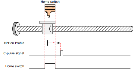
The HmRef signal is active initially, and the Motor directly starts homing in negative direction at low speed.
After reaching the falling edge of the HmRef signal, the Motor stops at the first Motor C-pulse signal.
6098h = 6
Home: the Motor C-pulse signal
Deceleration point: home switch (HmRef)
Deceleration point signal inactive at homing start:
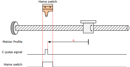
The HmRef signal is inactive initially, and the Motor directly starts homing in negative direction at low speed. After reaching the rising edge of the HmRef signal, the Motor stops at the first Motor C-pulse signal.
Deceleration point signal active at homing start:
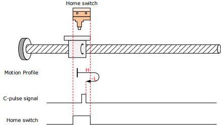
The HmRef signal is active initially, and the Motor starts homing in positive direction at high speed. After reaching the falling edge of the HmRef signal, the Motor decelerates and changes to run in negative direction at low speed.
After reaching the rising edge of the HmRef signal, the Motor stops at the first Motor C-pulse signal.
6098h = 7
Home: the Motor C-pulse signal
Deceleration point: home switch (HmRef)
Deceleration point signal inactive at homing start, not reaching positive limit switch:
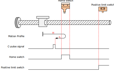
The HmRef signal is inactive initially, and the Motor starts homing in positive direction at high speed. If the Motor does not reach the limit switch, it decelerates and changes to run in negative direction at low speed after reaching the rising edge of the HmRef signal.
After reaching the falling edge of the HmRef signal, the Motor stops at the first Motor C-pulse signal.
Deceleration point signal inactive at homing start, reaching positive limit switch:
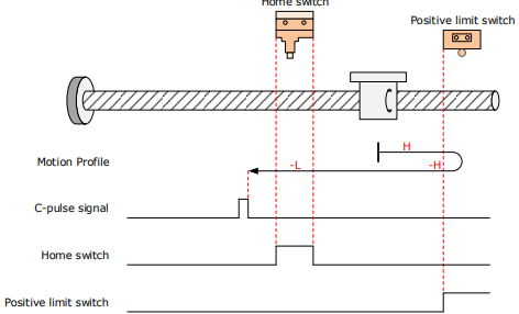
The HmRef signal is inactive initially, and the Motor starts homing in positive direction at high speed. If the Motor reaches the limit switch, it automatically changes to run in negative direction at high speed.
After reaching the rising edge of the HmRef signal, the Motor decelerates and continues to run in negative direction at low speed.
After reaching the falling edge of the HmRef signal, the Motor stops at the first Motor C-pulse signal.
Deceleration point signal active at homing start:
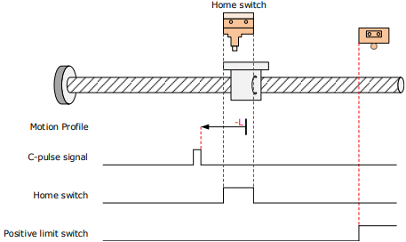
The HmRef signal is active initially, and the Motor directly starts homing in negative direction at low speed.
After reaching the falling edge of the HmRef signal, the Motor stops at the first Motor C-pulse signal.
6098h = 8
Home: the Motor C-pulse signal
Deceleration point: home switch (HmRef)
Deceleration point signal inactive at homing start, not reaching positive limit switch:
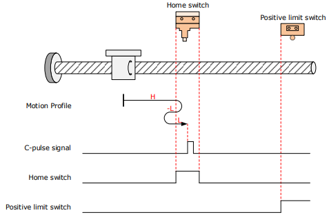
The HmRef signal is inactive initially, and the Motor starts homing in positive direction at high speed. If the Motor does not reach the limit switch, it decelerates and changes to run in negative direction at low speed after reaching the rising edge of the HmRef signal.
After reaching the falling edge of the HmRef signal, the Motor changes to run in positive direction at low speed, and stops at the first Motor C-pulse signal.
Deceleration point signal inactive at homing start, reaching positive limit switch:
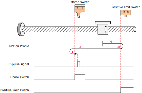
The HmRef signal is inactive initially, and the Motor starts homing in positive direction at high speed. If the Motor reaches the limit switch, it automatically changes to run in negative direction at high speed.
After reaching the rising edge of the HmRef signal, the Motor decelerates and continues to run in negative direction at low speed.
After reaching the falling edge of the HmRef signal, the Motor changes to run in positive direction at low speed, and stops at the first Motor C-pulse signal.
Deceleration point signal active at homing start:
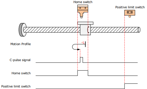
The HmRef signal is active initially, and the Motor directly starts homing in negative direction at low speed.
After reaching the falling edge of the HmRef signal, the Motor changes to run in positive direction at low speed.
After reaching the rising edge of the HmRef signal, the Motor stops at the first Motor C-pulse signal.
6098h = 9
Home: the Motor C-pulse signal
Deceleration point: home switch (HmRef)
Deceleration point signal inactive at homing start, not reaching positive limit switch:
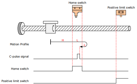
The HmRef signal is inactive initially, and the Motor starts homing in positive direction at high speed. If the Motor does not reach the limit switch, it decelerates and continues to run in positive direction at low speed after reaching the rising edge of the HmRef signal.
After reaching the falling edge of the HmRef signal, the Motor changes to run in negative direction at low speed, and stops at the first Motor C-pulse signal.
Deceleration point signal inactive at homing start, reaching positive limit switch:
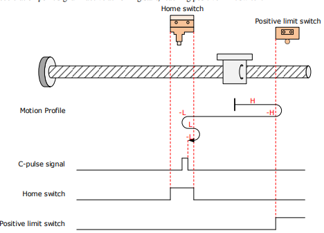
The HmRef signal is inactive initially, and the Motor starts homing in positive direction at high speed. If the Motor reaches the limit switch, it automatically changes to run in negative direction at high speed.
After reaching the rising edge of the HmRef signal, the Motor decelerates and resumes to run in positive direction at low speed.
After reaching the falling edge of the HmRef signal, the Motor changes to run in negative direction at low speed, and stops at the first Motor C-pulse signal.
Deceleration point signal active at homing start:
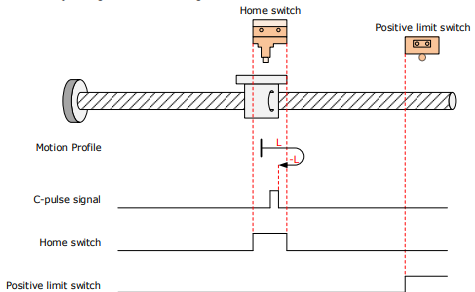
The HmRef signal is active initially, and the Motor directly starts homing in positive direction at low speed.
After reaching the falling edge of the HmRef signal, the Motor changes to run in negative direction at low speed.
After reaching the rising edge of the HmRef signal, the Motor stops at the first Motor C-pulse signal
6098h = 10
Home: the Motor C-pulse signal
Deceleration point: home switch (HmRef)
Deceleration point signal inactive at homing start, not reaching positive limit switch:
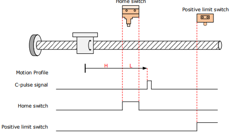
The HmRef signal is inactive initially, and the Motor starts homing in positive direction at high speed. If the Motor does not reach the limit switch, it decelerates and continues to run in positive direction at low speed after reaching the rising edge of the HmRef signal.
After reaching the falling edge of the HmRef signal, the Motor continues to run in positive direction at low speed, and stops at the first Motor C-pulse signal.
Deceleration point signal inactive at homing start, reaching positive limit switch:
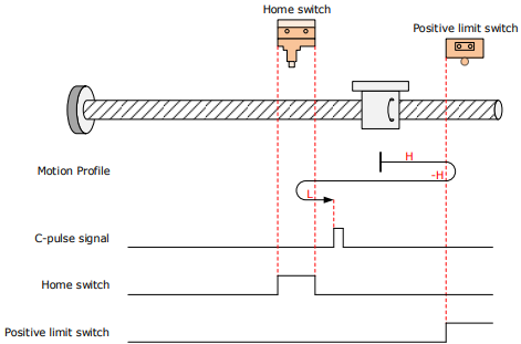
The HmRef signal is inactive initially, and the Motor starts homing in positive direction at high speed. If the Motor reaches the limit switch, it automatically changes to run in negative direction at high speed.
After reaching the falling edge of the HmRef signal, the Motor decelerates and resumes to run in positive direction at low speed.
After reaching the falling edge of the HmRef signal, the Motor stops at the first Motor C-pulse signal.
Deceleration point signal active at homing start:
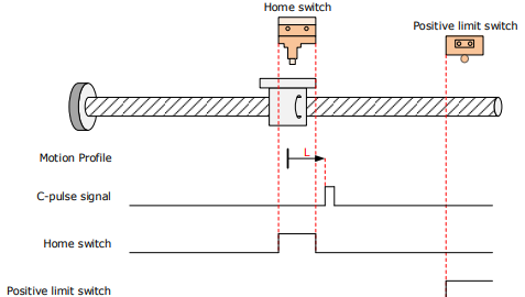
The HmRef signal is active initially, and the Motor directly starts homing in positive direction at low speed.
After reaching the falling edge of the HmRef signal, the Motor stops at the first Motor C-pulse signal.
6098h = 11
Home: the Motor C-pulse signal
Deceleration point: home switch (HmRef)
Deceleration point signal inactive at homing start, not reaching negative limit switch:
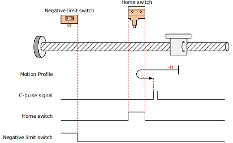
The HmRef signal is inactive initially, and the Motor starts homing in negative direction at high speed. If the Motor does not reach the limit switch, it decelerates and changes to run in positive direction at low speed after reaching edge of the HmRef signal.
After reaching the falling edge of the HmRef signal, the Motor stops at the first Motor C-pulse signal.
Deceleration point signal inactive at homing start, reaching negative limit switch:
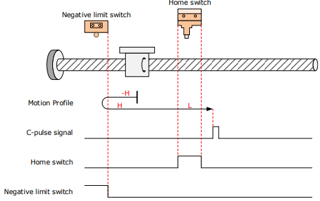
The HmRef signal is inactive initially, and the Motor starts homing in negative direction at high speed. If the Motor reaches the limit switch, it automatically changes to run in positive direction at high speed.
After reaching the rising edge of the HmRef signal, the Motor decelerates and continues to run in positive direction at low speed.
After reaching the falling edge of the HmRef signal, the Motor stops at the first Motor C-pulse signal.
Deceleration point signal active at homing start:
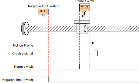
The HmRef signal is active initially, and the Motor directly starts homing in positive direction at low speed.
After reaching the falling edge of the HmRef signal, the Motor stops at the first Motor C-pulse signal.
6098h = 12
Home: the Motor C-pulse signal
Deceleration point: home switch (HmRef)
Deceleration point signal inactive at homing start, not reaching negative limit switch:
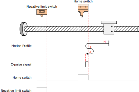
The HmRef signal is inactive initially, and the Motor starts homing in negative direction at high speed. If the Motor does not reach the limit switch, it decelerates and changes to run in positive direction at low speed after reaching the rising edge of the HmRef signal.
After reaching the falling edge of the HmRef signal, the Motor changes to run in negative direction at low speed, and stops at the first Motor C-pulse signal.
Deceleration point signal inactive at homing start, reaching negative limit switch:
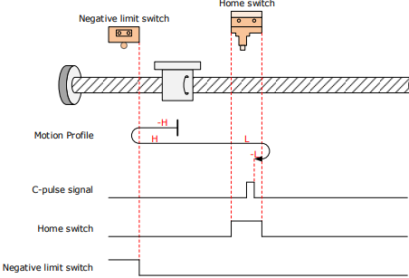
If the Motor reaches the limit switch, it automatically changes to run in positive direction at high speed.
After reaching the rising edge of the HmRef signal, the Motor decelerates and continues to run in positive direction at low speed.
After reaching the falling edge of the HmRef signal, the Motor changes to run in negative direction at low speed, and stops at the first Motor C-pulse signal.
Deceleration point signal active at homing start:
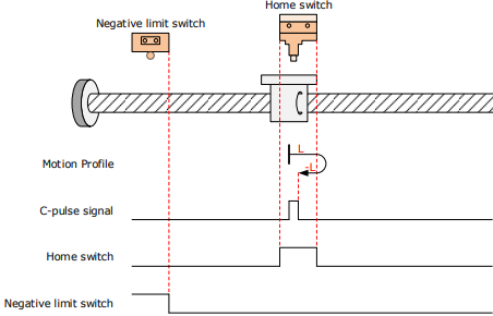
The HmRef signal is active initially, and the Motor directly starts homing in positive direction at low speed.
After reaching the falling edge of the HmRef signal, the Motor changes to run in negative direction at low speed.
After reaching the rising edge of the HmRef signal, the Motor stops at the first Motor C-pulse signal.
6098h = 13
Home: the Motor C-pulse signal
Deceleration point: home switch (HmRef)
Deceleration point signal inactive at homing start, not reaching negative limit switch:
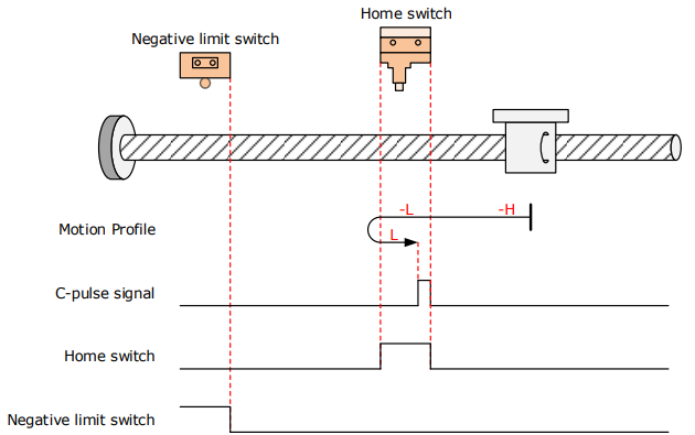
The HmRef signal is inactive, and the Motor starts homing in negative direction at high speed.
If the Motor does not reach the limit switch, it derelerates and continues to run in negative direction at low speed after reaching the rising edge of the HmRef signal.
After reaching the falling edge of the HmRef signal, the Motor changes to run in positive direction at low speed, and stops at the first Motor C-pulse signal.
Deceleration point signal inactive at homing start, reaching negative limit switch:
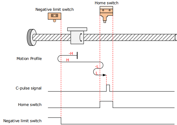
The HmRef signal is inactive initially, and the Motor starts homing in negative direction at high speed. If the Motor reaches the limit switch, it automatically changes to run in positive direction at high speed.
After reaching the rising edge of the HmRef signal, the Motor decelerates and changes to run in negative direction at low speed.
After reaching the falling edge of the HmRef signal, the Motor changes to run in positive direction at low speed, and stops at the first Motor C-pulse signal.
Deceleration point signal active at homing start:
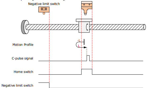
The HmRef signal is active initially, and the Motor directly starts homing in negative direction at low speed.
After reaching the falling edge of the HmRef signal, the Motor changes to run in positive direction at low speed.
After reaching the rising edge of the HmRef signal, the Motor stops at the first Motor C-pulse signal.
6098h = 14
Home: the Motor C-pulse signal
Deceleration point: home switch (HmRef)
Deceleration point signal inactive at homing start, not reaching negative limit switch:
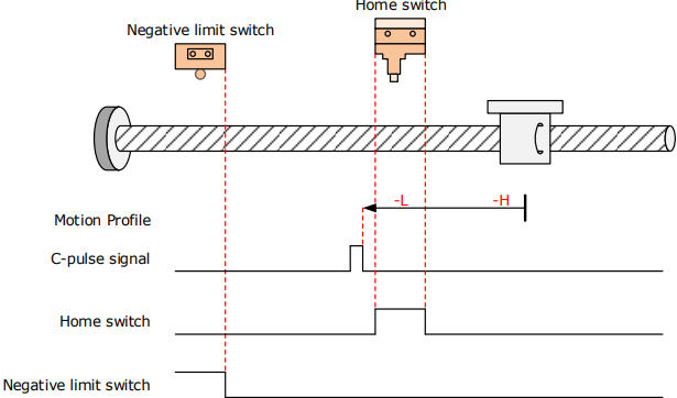
The HmRef signal is inactive initially, and the Motor starts homing in negative direction at high speed.
If the Motor does not reach the limit switch, it decelerates and continues to run in negative direction at low speed after reaching the rising edge of the HmRef signal.
After reaching the falling edge of the HmRef signal, the Motor continues to run in negative direction at low speed, and stops at the first Motor C-pulse signal.
Deceleration point signal inactive at homing start, reaching negative limit switch:
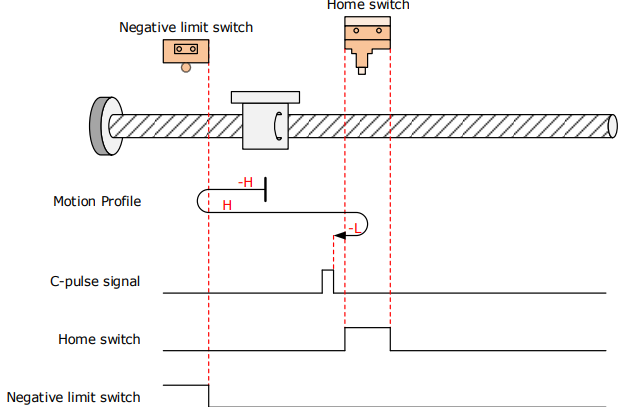
The HmRef signal is inactive initially, and the Motor starts homing in negative direction at high speed. If the Motor reaches the limit switch, it automatically changes to run in positive direction at high speed.
After reaching the rising edge of the HmRef signal, the Motor decelerates and changes to run in negative direction at low speed.
After reaching the falling edge of the HmRef signal, the Motor stops at the first Motor C-pulse signal.
Deceleration point signal active at homing start:
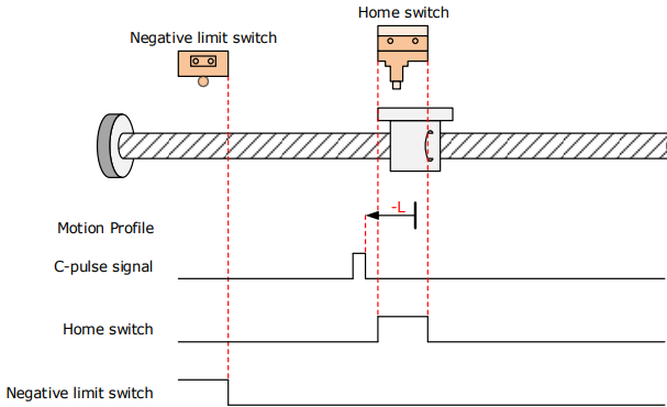
The HmRef signal is active initially, and the Motor directly starts homing in negative direction at low
speed. After reaching the falling edge of the HmRef signal, the Motor stops at the first Motor C-pulse signal.
6098h = 17
Home: negative limit switch (N-OT)
Deceleration point: negative limit switch (N-OT)
Deceleration point signal inactive at homig start:
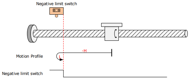
The N-OT signal is inactive initially, and the Motor starts homing in negative direction at high speed.
After reaching the rising edge of the N-OT signal, the Motor decelerates and changes to run in positive direction at low speed.
After reaching the falling edge of the N-OT signal, the Motor stops.
Deceleration point signal active at homig start:
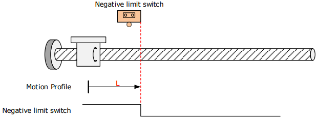
The N-OT signal is active initially, and the Motor directly starts homing in positive direction at low speed.
After reaching the falling edge of the N-OT signal, the Motor stops.
6098h = 18
Home: positive limit switch (P-OT)
Deceleration point: positive limit switch (P-OT)
Deceleration point signal inactive at homig start:
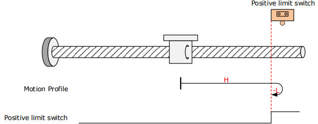
The P-OT signal is inactive initially, and the Motor starts homing in positive direction at high speed.
After reaching the rising edge of the P-OT signal, the Motor decelerates and changes to run in negative direction at low speed.
After reaching the falling edge of the P-OT signal, the Motor stops.
Deceleration point signal active at homig start:
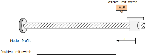
The P-OT signal is active initially, and the Motor directly starts homing in negative direction at low speed.
After reaching the falling edge of the P-OT signal, the Motor stops.
6098h = 19
Home: home switch (HmRef)
Deceleration point: home switch (HmRef)
Deceleration point signal inactive at homing start:
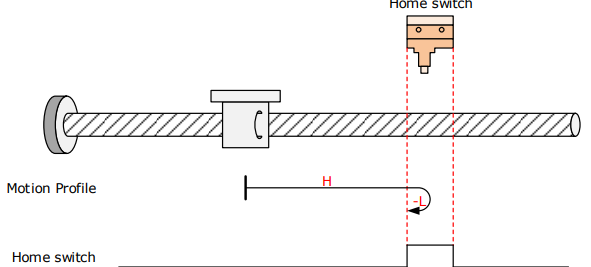
The HmRef signal is inactive initially, and the Motor starts homing in positive direction at high speed.
After reaching the rising edge of the HmRef signal, the Motor decelerates and changes to run in negative direction at low speed.
After reaching the falling edge of the HmRef signal, the Motor stops.
Deceleration point signal active at homing start:
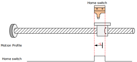
The HmRef signal is active initially, and the Motor directly starts homing in negative direction at low speed.
After reaching the falling edge of the HmRef signal, the Motor stops.
6098h = 20
Home: home switch (HmRef)
Deceleration point: home switch (HmRef)
Deceleration point signal inactive at homing start:
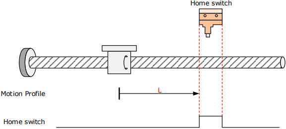
The HmRef signal is inactive initially, and the Motor starts homing in positive direction at low speed.
After reaching the rising edge of the HmRef signal, the Motor stops.
Deceleration point signal active at homing start:
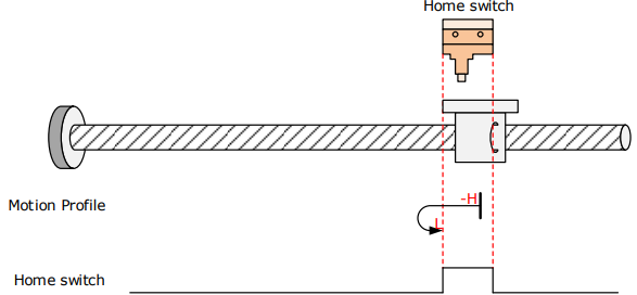
The HmRef signal is active initially, and the Motor starts homing in negative direction at high speed.
After reaching the falling edge of the HmRef signal, the Motor decelerates and changes to run in positive direction at low speed.
After reaching the rising edge of the HmRef signal, the Motor stops.
6098h = 21
Home: home switch (HmRef)
Deceleration point: home switch (HmRef)
Deceleration point signal inactive at homing start:
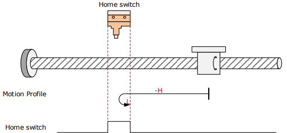
The HmRef signal is inactive initially, and the Motor starts homing in negative direction at high speed.
After reaching the rising edge of the HmRef signal, the Motor decelerates and changes to run in positive direction at low speed.
After reaching the falling edge of the HmRef signal, the Motor stops.
Deceleration point signal active at homing start:
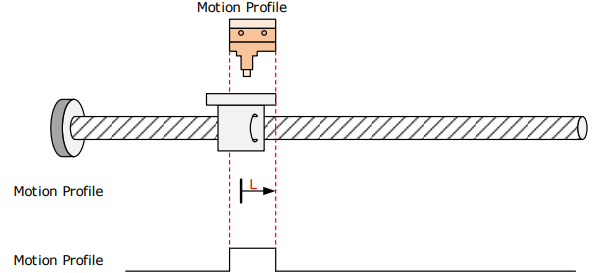
The HmRef signal is active initially, and the Motor directly starts homing in positive direction at low speed.
After reaching the falling edge of the HmRef signal, the Motor stops.
6098h = 22
Home: home switch (HmRef)
Deceleration point: home switch (HmRef)
Deceleration point signal inactive at homing start:
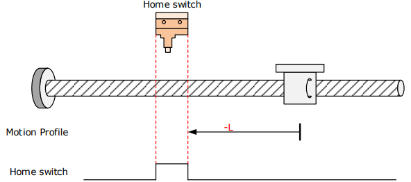
The HmRef signal is inactive initially, and the Motor directly starts homing in negative direction at low speed.
After reaching the rising edge of the HmRef signal, the Motor stops.
Deceleration point signal active at homing start:
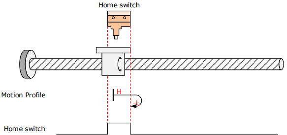
The HmRef signal is active initially, and the Motor starts homing in positive direction at high speed.
After reaching the falling edge of the HmRef signal, the Motor decelerates and changes to run in negative direction at low speed.
After reaching the rising edge of the HmRef signal, the Motor stops.
6098h = 23
Home: home switch (HmRef)
Deceleration point: home switch (HmRef)
Deceleration point signal inactive at homing start, not reaching positive limit switch:
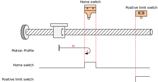
The HmRef signal is inactive initially, and the Motor starts homing in positive direction at high speed.
If the Motor does not reach the limit switch, it decelerates and changes to run in negative direction at low speed after reaching the rising edge of the HmRef signal.
After reaching the falling edge of the HmRef signal, the Motor stops.
Deceleration point signal active at homing start, reaching positive limit switch:
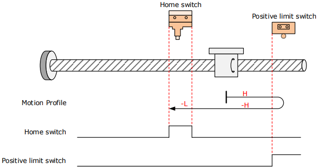
The HmRef signal is inactive initially, and the Motor starts homing in positive direction at high speed.
If the Motor reaches the limit switch, it automatically changes to run in negative direction at high speed.
After reaching the rising edge of the HmRef signal, the Motor decelerates and continues to run in negative direction at low speed.
After reaching the falling edge of the HmRef signal, the Motor stops.
Deceleration point signal active at homing start:
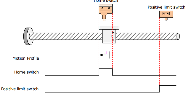
The HmRef signal is active initially, and the Motor directly starts homing in negative direction at low speed.
After reaching the falling edge of the HmRef signal, the Motor stops.
6098h = 24
Home: home switch (HmRef)
Deceleration point: home switch (HmRef)
Deceleration point signal inactive at homing start, not reaching positive limit switch
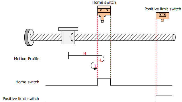
The HmRef signal is inactive initially, and the Motor starts homing in positive direction at high speed.
If the Motor does not reach the limit switch, it decelerates and changes to run in negative direction at low speed after reaching the rising edge of the HWsignal.
After reaching the falling edge of the HmRef signal, the Motor changes to run in positive direction at low speed, and stops at the rising edge of the HmRef signal.
Deceleration point signal inactive at homing start, reaching positive limit switch:
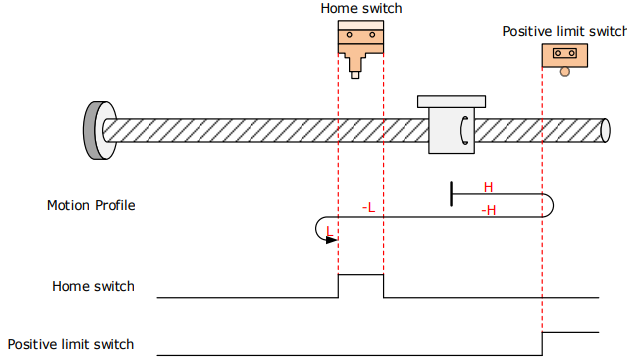
The HmRef signal is inactive initially, and the Motor starts homing in positive direction at high speed.
If the Motor reaches the limit switch, it automatically changes to run in negative direction at high speed.
After reaching the rising edge of the HmRef signal, the Motor decelerates and continues to run in negative direction at low speed.
After reaching the falling edge of the HmRef signal, the Motor changes to run in positive direction at low speed, and stops at the rising edge of the HmRef signal.
Deceleration point signal active at homing start
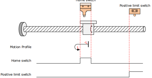
The HmRef signal is active initially, and the Motor starts homing in negative direction at low speed.
After reaching the falling edge of the HmRef signal, the Motor changes to run in positive direction at low speed.
After reaching the rising edge of the HmRef signal, the Motor stops.
6098h = 25
Home: home switch (HmRef)
Deceleration point: home switch (HmRef)
Deceleration point signal inactive at homing start, not reaching positive limit switch:
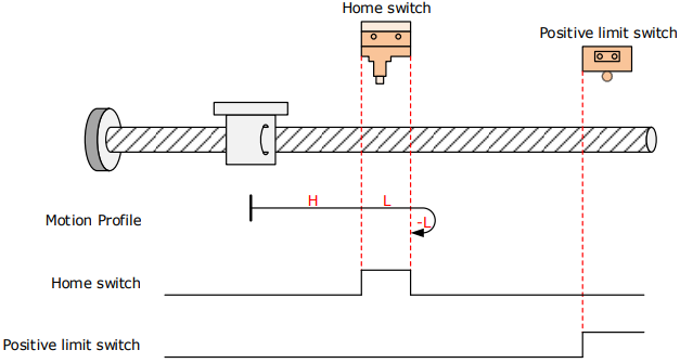
The HmRef signal is inactive initially, and the Motor starts homing in positive direction at high speed.
If the Motor does not reach the limit switch, it decelerates and continues to run in positive direction at low speed after reaching the rising edge of the HmRef signal.
After reaching the falling edge of the HmRef signal, the Motor changes to run in negative direction at low speed, and stops at the rising edge of the HmRef signal.
Deceleration point signal inactive at homing start, reaching positive limit switch:
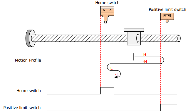
The HmRef signal is inactive initially, and the Motor starts homing in positive direction at high speed.
If the Motor reaches the limit switch, it automatically changes to run in negative direction at high speed.
After reaching the rising edge of the HmRef signal, the Motor decelerates and resumes to run in positive direction at low speed.
After reaching the falling edge of the HmRef signal, the Motor changes to run in negative direction at low speed, and stops at the rising edge of the HmRef signal.
Deceleration point signal active at homing start:
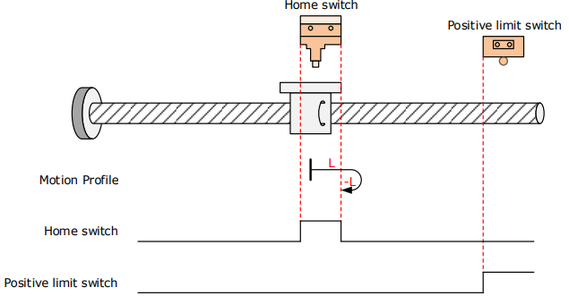
The HmRef signal is active initially, and the Motor directly starts homing in positive direction at low speed.
After reaching the falling edge of the HmRef signal, the Motor changes to run in negative direction at low speed.
After reaching the rising edge of the HmRef signal, the Motor stops.
6098h = 26
Home: home switch (HmRef)
Deceleration point: home switch (HmRef)
Deceleration point signal inactive at homing start, not reaching positive limit switch
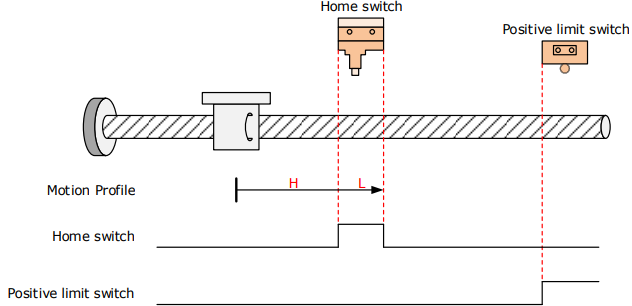
The HmRef signal is inactive initially, and the Motor starts homig in positive direction at high speed.
If the Motor does not reach the limit switch, it decelerates and continues to run in positive direction at low speed after reaching the rising edge of the HmRef signal.
After reaching the falling edge of the HmRef signal, the Motor stops.
Deceleration point signal inactive at homing start, reaching positive limit switch
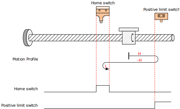
The HmRef signal is inactive initially, and the Motor starts homing in positive direction at high speed.
If the Motor reaches the limit switch, it automatically changes to run in negative direction at high speed.
After reaching the rising edge of the HmRef signal, the Motor decelerates and resumes to run in positive direction at low speed.
After reaching the falling edge of the HmRef signal, the Motor stops.
Deceleration point signal active at homing start:
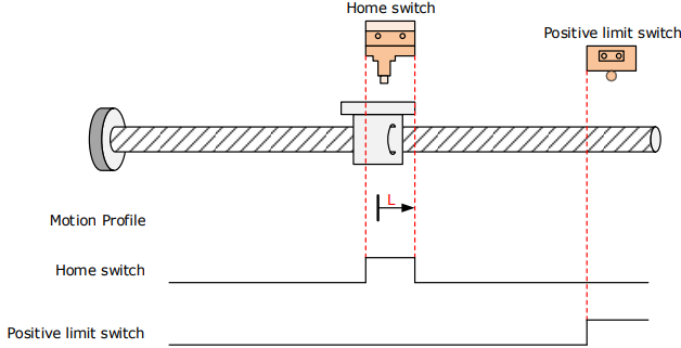
The HmRef signal is active initially, and the Motor directly starts homing in positive direction at low speed.
After reaching the falling edge of the HmRef signal, the Motor stops.
6098h = 27
Home: home switch (HmRef)
Deceleration point: home switch (HmRef)
Deceleration point signal inactive at homing start, not reaching negative limit switch
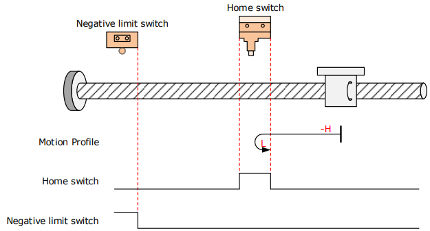
The HmRef signal is inactive initially, and the Motor starts homing in neagative direction at high speed.
If the Motor does not reach the limit switch, it decelerates and changes to run in positive direction at low speed after reaching the rising edge of the HmRef signal.
After reaching the falling edge of the HmRef signal, the Motor stops.
Deceleration point signal inactive at homing start, reaching negative limit switch:
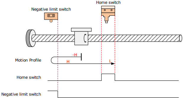
The HmRef signal is inactive initially, and the Motor starts homing in negative direction at high speed.
If the Motor reaches the limit switch, it automatically changes to run in positive direction at high speed.
After reaching the rising edge of the HmRef signal, the Motor decelerates and continues to run in positive direction at low speed.
After reaching the falling edge of the HmRef signal, the Motor stops
Deceleration point signal active at homing start:
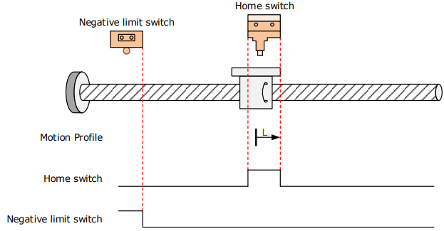
The HmRef signal is active initially, and the Motor directly starts homing in positive direction at low speed.
After reaching the falling edge of the HmRef signal, the Motor stops.
6098h = 28
Home: home switch (HmRef)
Deceleration point: home switch (HmRef)
Deceleration point signal inactive at homing start, not reaching negative limit switch
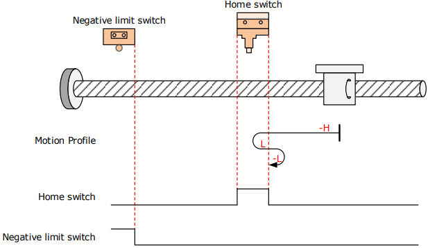
The HmRef signal is inactive initially, and the Motor starts homing in negative direction at high speed.
If the Motor does not reach the limit switch, it decelerates and changes to run in positive direction at low speed after reaching the rising edge of the HmRef signal.
After reaching the falling edge of the HmRef signal, the Motor changes to run in negative direction at low speed, and stops at the rising edge of the HmRef signal.
Deceleration point signal inactive at homing start, reaching negative limit switch
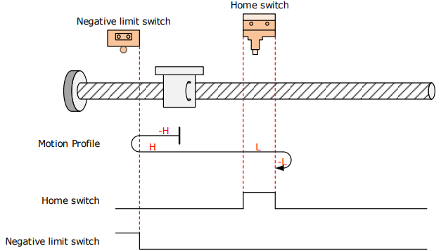
The HmRef signal is inactive initially, and the Motor starts homing in negative direction at high speed.
If the Motor reaches the limit switch, it automatically changes to run in positive direction at high speed.
After reaching the rising edge of the HmRef signal, the Motor decelerates and continues to run in positive direction at low speed.
After reaching the falling edge of the HmRef signal, the Motor changes to run in negative direction at low speed, and stops at the rising edge of the HmRef signal.
Deceleration point signal active at homing start:
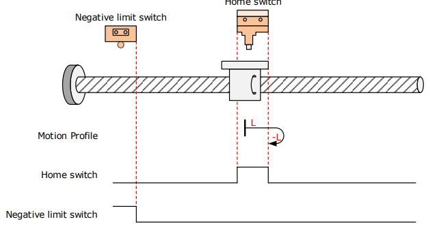
The HmRef signal is active initially, and the Motor directly starts homing in positive direction at low speed.
After reaching the falling edge of the HmRef signal, the Motor changes to run in negative direction at low speed.
After reaching the rising edge of the HmRef signal, the Motor stops.
6098h = 29
Home: home switch (HmRef)
Deceleration point: home switch (HmRef)
Deceleration point signal inactive at homing start, not reaching negative limit switch:
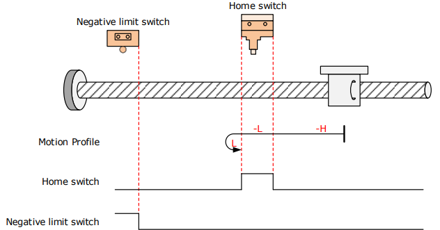
The HmRef signal is inactive initially, and the Motor starts homing in negative direction at high speed.
If the Motor does not reach the limit switch, it decelerates and continues to run in negative direction at low speed after reaching the rising edge of the HmRef signal.
After reaching the falling edge of the HmRef signal, the Motor changes to run in positive direction at low speed, and stops at the rising edge of the HmRef signal.
Deceleration point signal inactive at homing start, reaching negative limit switch
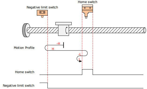
The HmRef signal is inactive initially, and the Motor starts homing in negative direction at high speed.
If the Motor reaches the limit switch, it automatically changes to run in positive direction at high speed.
After reaching the rising edge of the HmRef signal, the Motor decelerates and changes to run in negative direction at low speed.
After reaching the falling edge of the HmRef signal, the Motor changes to run in positive direction at low speed, and stops at the rising edge of the HW signal
Deceleration point signal active at homing start:
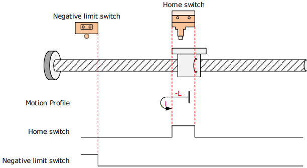
The HmRef signal is active initially, and the Motor directly starts homing in negative direction at low speed.
After reaching the falling edge of the HmRef signal, the Motor changes to run in positive direction at low speed.
After reaching the rising edge of the HmRef signal, the Motor stops.
6098h = 30
Home: home switch (HmRef)
Deceleration point: home switch (HmRef)
Deceleration point signal inactive at homing start, not reaching negative limit switch:
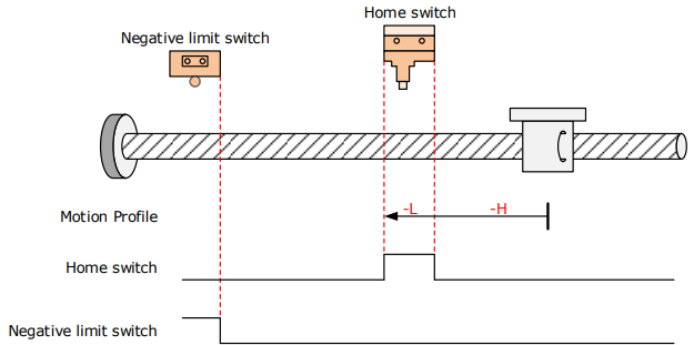
The HmRef signal is inactive initially, and the Motor starts homing in negative direction at high speed.
If the Motor does not reach the limit switch, it decelerates and continues to run in negative direction at low speed after reaching the rising edge of the HmRef signal.
After reaching the falling edge of the HmRef signal, the Motor stops.
Deceleration point signal inactive at homing start, reaching negative limit switch:
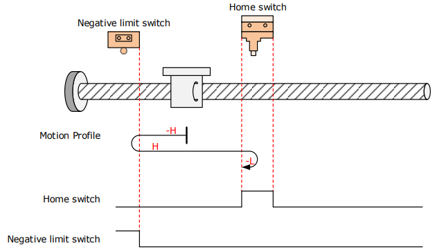
The HmRef signal is inactive initially, and the Motor starts homing in negative direction at high speed.
If the Motor reaches the limit switch, it automatically changes to run in positive direction at high speed.
After reaching the rising edge of the HmRef signal, the Motor decelerates and changes to run in negative direction at low speed.
After reaching the falling edge of the HmRef signal, the Motor stops.
Deceleration point signal active at homing start:
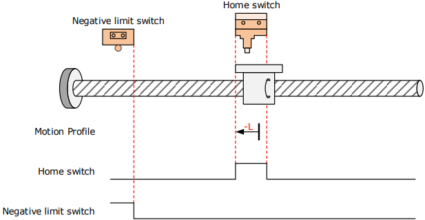
The HmRef signal is active initially, and the Motor directly starts homing in negative direction at low speed.
After reaching the falling edge of the HmRef signal, the Motor stops
6098h = 33
Home: the Motor C-pulse signal
Deceleration point: None
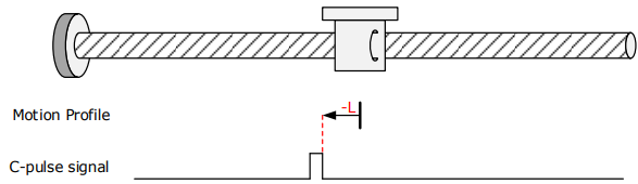
The Motor runs in negative direction at low speed, and stops at the first Motor C-pulse signal.
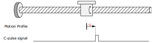
6098h = 34
Home: the Motor C-pulse signal
Deceleration point: None
6098h=35
Home: the current position
Deceleration point: None

The current position is the home. The Motor starts homing after the homing signal is triggered. (Control word 6040h: 0x0F → 0x1F)
6.6 Velocity Control
6.6.1 Profile Velocity (PV) Mode
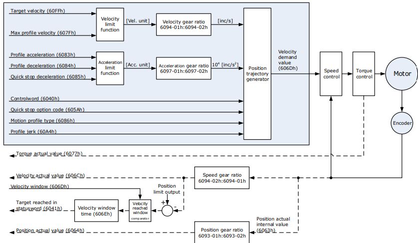
In this mode of operation, the host controller gives the target speed, acceleration, and deceleration to the Drive. Speed control and torque control are performed by the Drive.
Block Diagram
Speed Limit
The speed limit is determined by the smaller of 6080h value and 607F value.
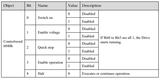
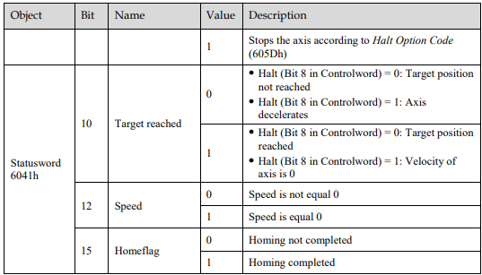
Relevant Objects
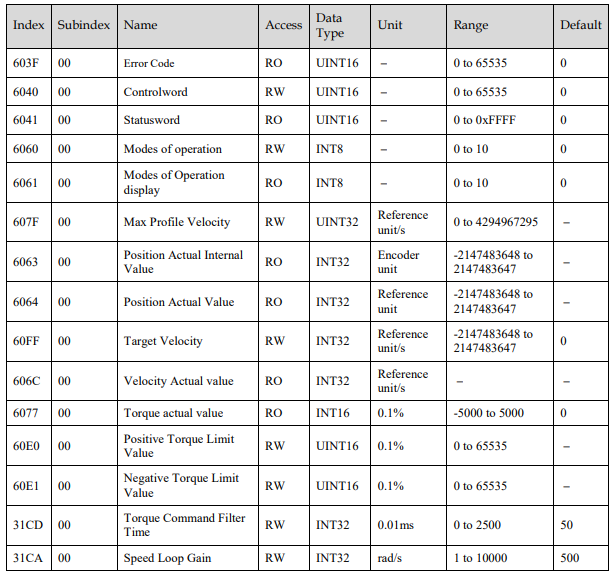
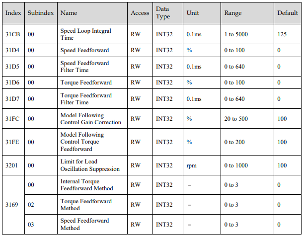
Recommended Configuration
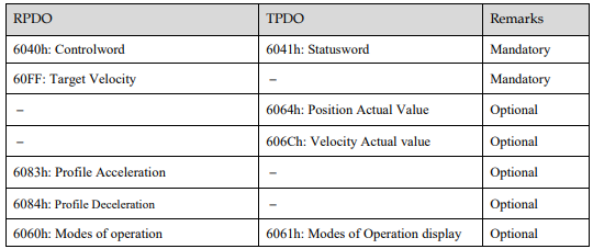
6.6.2 Cyclic Synchronous Velocity (CSV) Mode
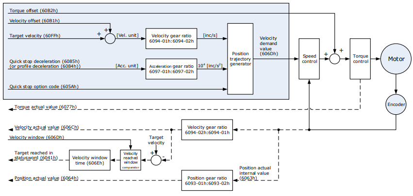
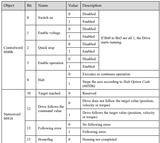
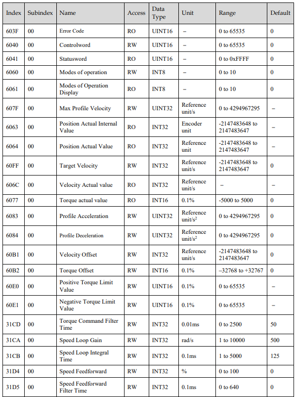
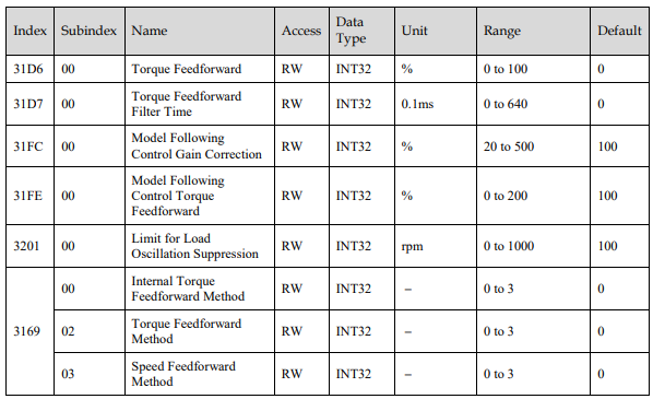
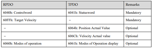
In this mode of operation, the host controller gives the target speed in 60FFh to the Drive using cyclic synchronization. Speed control and torque control are performed by the Drive.
Block Diagram
Speed Limit
The speed limit is determined by the smaller of 6080h value and 607F value.
Relevant Objects

Recommended Configuration
6.7 Torque Control
6.7.1 Profile Torque (PT) Mode
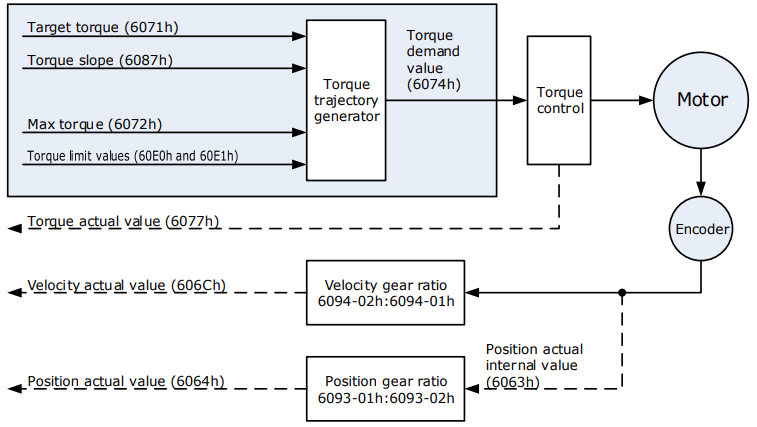
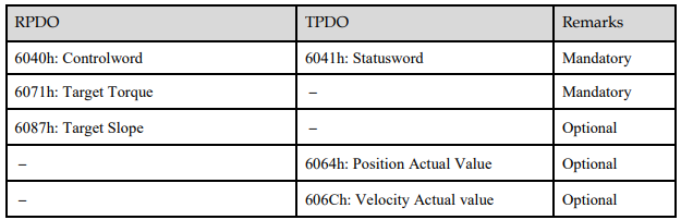
In this mode of operation, the host controller gives the target torque in 6071h and torque slope in 6087h to the Drive. Torque control is performed by the Drive. The Drive regulates the speed when the speed reaches the limit.
Block Diagram
Speed Limit
The speed limit is determined by the smaller of 6080h value and 607F value.
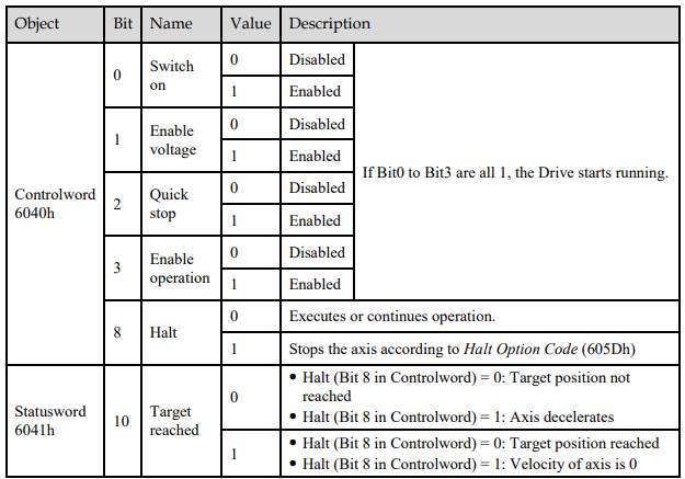
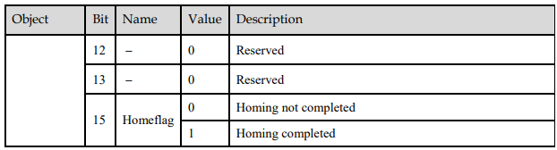
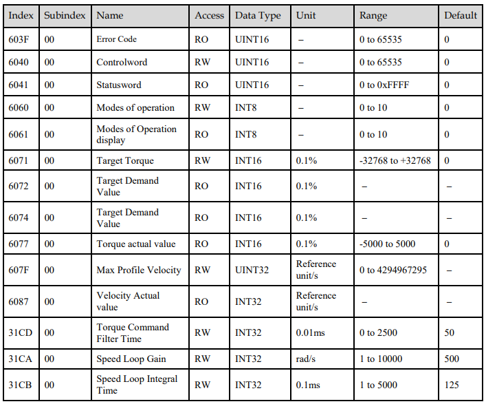
Relevant Objects
Recommended Configuration

6.7.2 Cyclic Synchronous Torque (CST) Mode
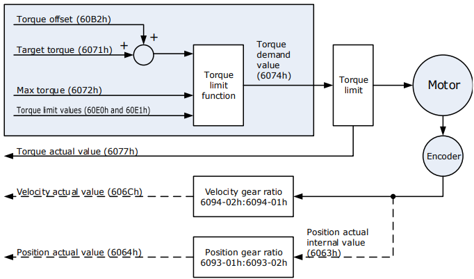
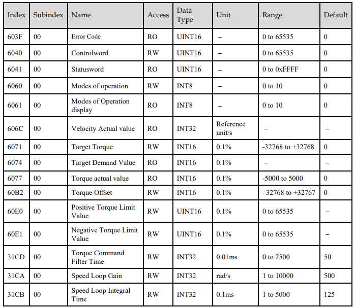
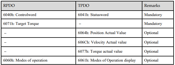
In this mode of operation, the host controller gives the target torque in 6071h to the Drive using cyclic synchronization. Torque control is performed by the Drive. The Drive regulates the speed when the speed reaches the limit.
Block Diagram
Speed Limit
The speed limit is determined by the smaller of 6080h value and 607F value.
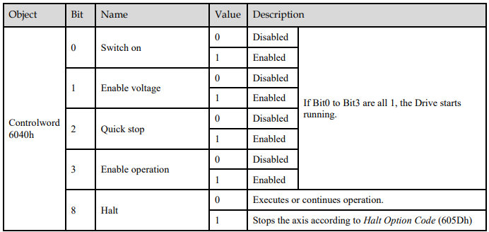
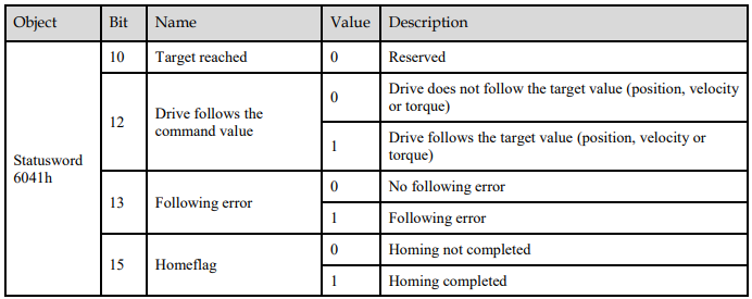
Relevant Objects
Recommended Configuration
6.8 Torque Limits
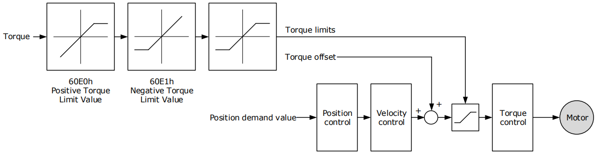
The following figure shows the block diagram for the torque limits. The torque is limited by the objects 60E0h and 60E1h.
Positive Torque Limit Value (60E0h)
This object sets the positive torque limit. Set the value in units of 0.1% of the Motor rated torque.
The positive torque limit value is the smaller of 6072h and 60E0h

Negative Torque Limit Value (60E1h)
This object sets the negative torque limit. Set the value in units of 0.1% of the Motor rated torque.
The negative torque limit value is the smaller of 6072h and 60E1h.

6.9 Digital and Remote I/O Signals
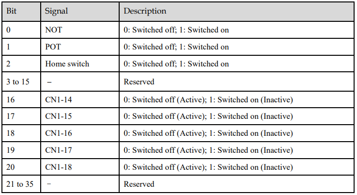
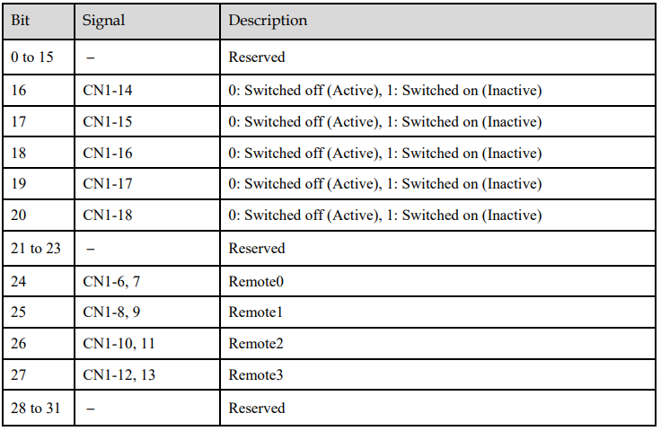
Digital Inputs (60FDh)
This object gives the status of the digital inputs to CN1 on the Drive.


Digital Outputs (60FEh)
This object controls the status of both general-purpose output signals and remote output signals from CN1 on the Drive. 60FE-01h is used to control the status of the output signals. 60FE-02h determines which output signals in subindex 1 are enabled.
The Bit16 to Bit19 in 60FE-01h can only assign to the general-purpose output signals on CN1, and set the Bit mask (60EF-02h) to 1 for enabling them. And then, according to the settings of Pn509 and Pn510 to allocate the desired signals, also you can choose whether to reverse them by the setting of Pn516 and Pn517.
For the bits transmitted on the bus, you also need to set Pn512 and Pn513 to enable it.
The Bit24 to Bit27 in 60FE-01h can assign to the remote output signals on CN1, and according to the setting of Pn511 to allocate the desired signals, using as a remote IO for the master station.


6.10 Touch Probe
You can latch the feedback position with the following trigger events.
Trigger with Touch Probe Input 1 (EXT1 signal)
Trigger with Touch Probe Input 2 (EXT2 signal)
Trigger with encoder zero signal (phase C)
The following two touch probe latches can be used at the same time.
Touch Probe Input 1
− Latch control object: 60B8h (bits 0 to 7)
− Latch status object: 60B9h (bits 0 to 7)
− The latched position is always stored in touch probe 1 position value (60BAh and 60BBh).
− Trigger signal: Encoder zero signal or EXT1 signal
Touch Probe Input 2
− Latch control object: 60B8h (bits 8 to 15)
− Latch status object: 60B9h (bits 8 to 15)
− The latched position is always stored in touch probe 2 position value (60BCh and 60BDh).
− Trigger signal: Encoder zero signal or EXT2 signal
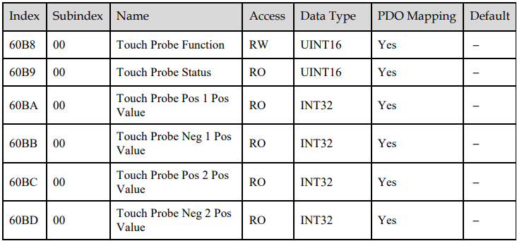
The relevant objects used in this function are as following:
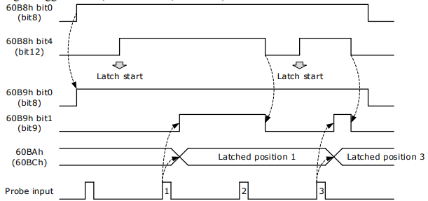
The examples of execution procedure for a Touch Probe are as following:
Single Trigger Mode (60B8h bit1=0, or bit9=0)
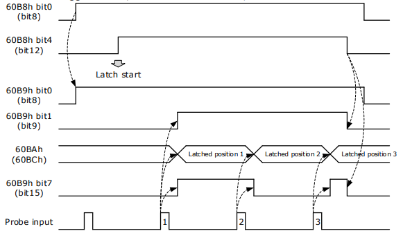
Continuous Trigger Mode (60B8h bit1=1, or bit9=1)
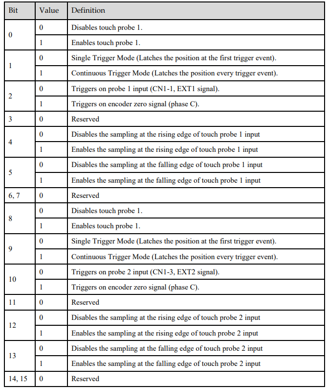
60B8h: Touch Probe Function
This object sets the touch probes.

The data description is as following.
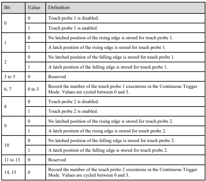
60B9h: Touch Probe Status
This object gives the status of the touch probes.

60BAh: TouchProbePos1PosValue
This object gives the latched position of the rising edge for touch probe 1.

60BBh: TouchProbeNeg1PosValue
This object gives the latched position of the falling edge for touch probe 1.

60BCh: TouchProbePos2PosValue
This object gives the latched position of the rising edge for touch probe 2.

60BDh: TouchProbeNeg2PosValue
This object gives the latched position of the falling edge for touch probe 2.

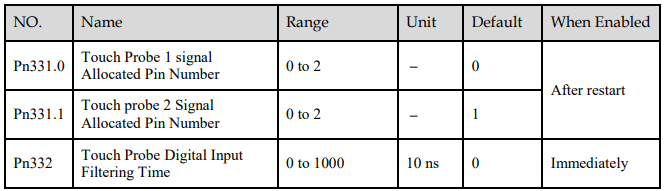
Pn331, Pn332
You can allocate the touch probe functions by Pn331, and set Touch Probe Digital Input Filtering Time by Pn332. The relevant parameters are as following:
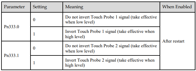
Pn333
You can select whether to invert the Touch Probe 1 and Touch Probe 2 signals through the parameter Pn333. In General, it needs to be set according to the actual input signal level.
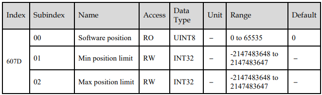
6.11 Soft Limit Function
This object defines the absolute positions of the limits to the target position (position demand value). Every target position is checked against these limits.
The limit positions are specified in user-defined position reference units, the same as for target positions, and are always relative to the machine home position.
The limit values are corrected internally for the home offset as given below. The target positions are compared with the corrected values.
Corrected minimum position limit = Min position limit – Home offset (607Ch)
Corrected maximum position limit = Max position limit – Home offset (607Ch)
The software position limits are enabled at the following times:
When homing is completed
When an absolute encoder is connected
The software limits are enabled if Min position limit < Max position limit.
No comments to display
No comments to display