
2. Installation
2.1 Installation Precautions
Installation Near Sources of Heat
⚫ Implement measures to prevent temperature increases caused by external heat sources so that the ambient temperature of the Drive is within the specified limits.
Installation Near Sources of Vibration
⚫ Install a vibration absorber on the installation surface of the Drive so that the Drive will not be subjected to vibration.
Other Precautions
⚫ Never install the Drive in a location subject to high temperatures, high humidity, water drops, cutting oil, excessive dust, excessive dirt, excessive iron powder, corrosive gases, or radioactivity.
2.2 Mounting Types and Orientation
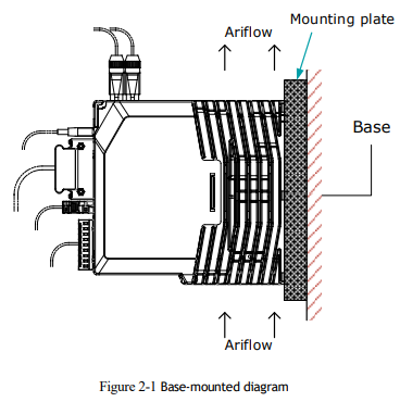
The Drives are based mounted and should be fitted to a non-painted metal surface. Mount the Drive vertically, as is shown in Figure 2-1.
Mount the Drives so that the Display Panel is facing toward the operator. Prepare two or three mounting holes for the Drive and mount it securely in the mounting holes (The number of mounting holes depends on the size of the Drive).
2.3 Mounting Hole Dimensions
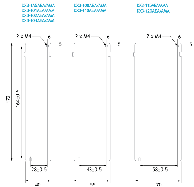
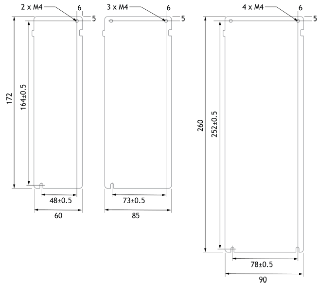
Use all mounting holes to securely mount the Drive to the mounting surface.
To mount the Drive, use a screwdriver that is longer than the depth of the Drive.
Wiring diagram for mounting holes of 200VAC units.
Wiring diagram for mounting holes of 400VAC units
2.4 Mounting Interval
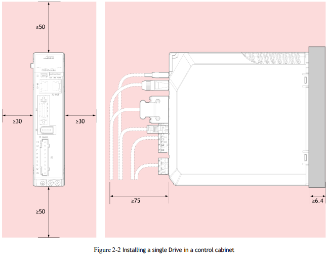
Installing One Drive in a Control Cabinet
When installing a single Drive use Figure 2-2 as a reference for free space around the installation.
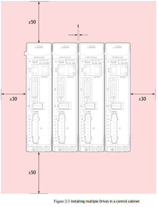
Installing multiple Drives in a Control Cabinet
When installing multiple Drives use Figure 2-3 as a reference for free space around the installation

No comments to display
No comments to display