
6. CANopen Communication
6.1 Wiring and Connection
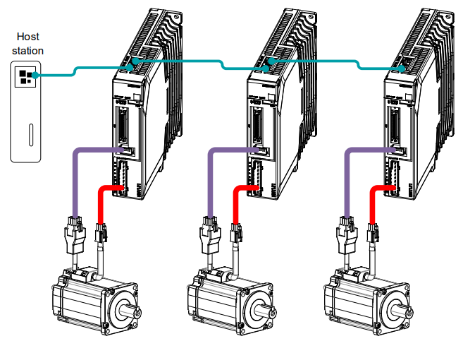
Connection diagram
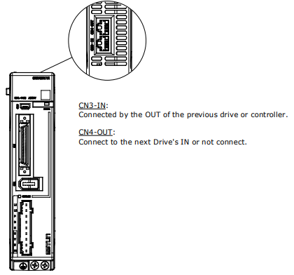
Terminal arrangement
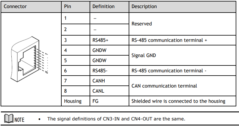
Signal Definition
The external communication connection terminals (CN3-IN and CN4-OUT) are of RJ45 connectors. The interface line as the master or controller is connected from CN3-IN, and CN4-OUT is connected to the CN3- IN terminal of next drive (slave).
Wiring Instructions
When wiring the CANopen communication, following precarious shall be taken.
⚫ Do not short connect pin 1 and pin 2.
⚫ Use UTPs (at least 2 pairs) with shielding layer.
One pair of UTPs is connected to CANL and CANH; the other is connected to ISO_GND.
⚫ The shielding layer is generally grounded reliably at a single point.
⚫ To prevent signal reflection, it is recommended to connect two 120Ω (1%, 1/4W) terminal matched
resistors at both ends of the bus.
⚫ It is recommended that the CAN bus networking node is ≤16.
The wiring diagram is shown below.

6.2 CANopen Overview
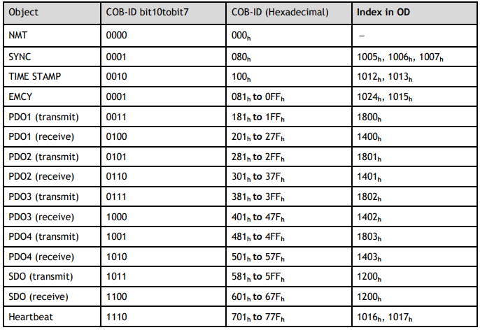
6.2.1 CAN Identifier List
6.2.2 Service Data Objects (SDO)
SDO is used to visit the object dictionary of a device. A visitor is called a client. The CANopen device whose object dictionary is visited and required to supply the asked service is called server. CANopen messages from a client and servo all contain 8 bits (not all of them are meaningful). A request from a client must be confirmed by a server.
There are 2 methods of transferring SDO:
⚫ Expedited transfer contains 4 bytes at maximum
⚫ Segmented transfer: contains more than 4 bytes
Basic structure of SDO:

SDO read/write structure:
SDO message format for parameter read/write operation:
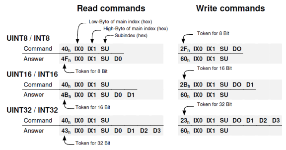
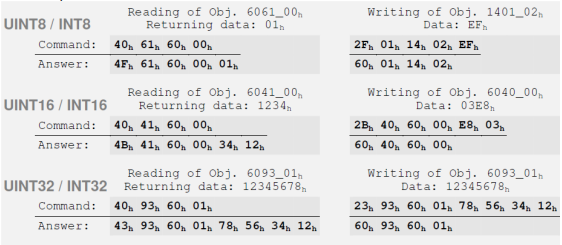
For example:
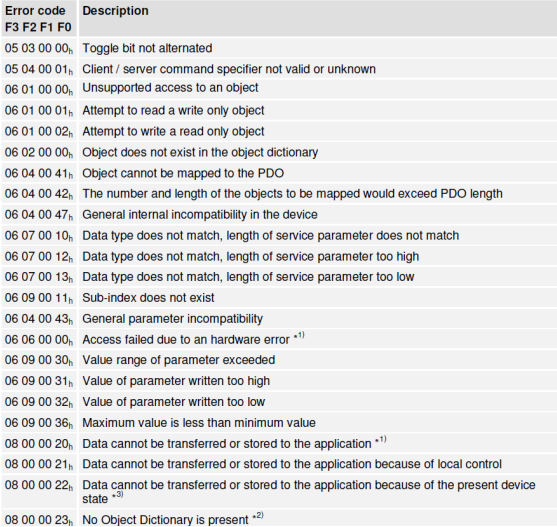
Format of SDO read/write error message:

Error code is defined as follows:
6.2.3 Process Data Objects (PDO)
PDO is applied to transferring real time data which will be conveyed from a producer to one or multiple clients. Data transferring will be limited to 1 to 8 bytes. There is no hand-shake restriction in PDO communication, which means data has been redefined, so clients could process the received data for a very short time. PDO content will be only defined by its CAN ID, assuming producers and clients know PDO content from its CAN ID.
2 objects in the object dictionary are used for each PDO.
⚫ PDO communication parameter: It contains COB-ID, transferring type, restriction time and cycle of timer used by PDO.
⚫ PDO mapping parameter: It contains a list of objects in the object dictionary. These objects are mapped into PDO, including their data length in bits. Producers and clients must know this mapping to explain the content of PDO.
The content of PDO’s message is predefined or configured when the network initializes. Mapping application objects into PDO is described in object dictionary. If a device (producer and client) supports dynamic mapping, SDO could be used to configure PDO’s mapping parameter. Our servo drive supports dynamic PDO mapping. There are 2 rules for PDO mapping to follow:
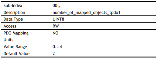
⚫ Each PDO could be mapped into 4 objects.
⚫ The length of each PDO will be no more than 64 bits.
PDO mapping process
1. Set the sub-index of PDO coordinated mapping parameter (e.g., 1600 h or 1A00 h) as o.
2. Revise the sub-index from 1 to 4 of PDO coordinated mapping parameter (e.g., 1600 h or 1A00 h).
3. Set the sub-index 0 of PDO coordinated mapping parameter (e.g., 1600 h or 1A00 h) as legal Number (number of PDO’s mapping objects)
4. PDO mapping completed.
Ways to transmit PDO
⚫ Synchronous (synchronization by receiving SYNC object)
Cycle: Transmission triggered after every 1 to 240 SYNC messages.
⚫ Asynchronous
Transmission triggered by special object event regulated in sub-object protocol.
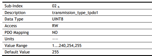
Definition of transmission type of PDO

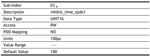
One PDO could set a frozen time which is the shortest time interval between 2 continuous PDO. It could prevent the bus from being occupied by amount of data with high priority. Frozen time is defined by 16-bit unsigned integer number and its unit is 100us
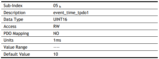
One PDO could set a timing period. When the regulated time is violated, a PDO transmit could be triggered without a trigger bit. Object timing period is defined as 16-bit unsigned integer and its unit is 1ms.
PDO mapping example
Map the 3 objects to PDO1 (transmit). PDO1 (transmit) is required to be asynchronous periodic type with period time as much as 10ms and frozen time as much as 2ms.

Step 1 Clear number_of_mapped_objects
number_of_mapped_objects(1A00 h: 00 h)= 0
Step 2 Set the parameter for mapping objects
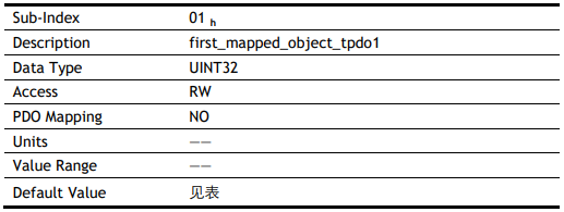
Index =6041 h Subin. = 00h Length = 10 h ⇒ 1st_mapped_object(1A00 h: 01 h)= 60410010 h
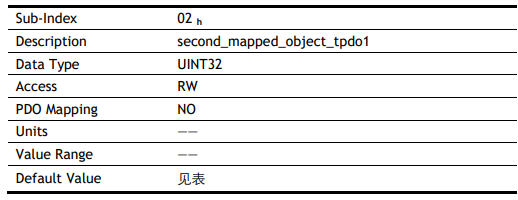
Index =6061 h Subin. = 00h Length = 08 h ⇒ 2nd_mapped_object(1A00 h: 02 h)= 60610008 h
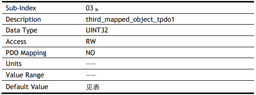
Index =60FD h Subin. = 00h Length = 20 h ⇒ 3rd_mapped_object(1A00 h: 03 h) = 60FD0020 h
Step 3 Set number_of_mapped_objects
number_of_mapped_objects(1A00 h: 00 h)= 3
Step 4 Set PDO communication parameter
PDO1 (transmit) is asynchronous periodical type ⇒ transmit_type (1800 h: 02 h)= FF h
Frozen time 2ms(20×100us) ⇒ inhibit_time (1800 h: 03 h)= 14 h
Period time 10ms(10×1ms) ⇒ event_time (1800 h: 05 h)= 0A h
Step 5 PDO mapping completed.
PDO Parameters
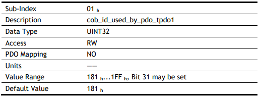
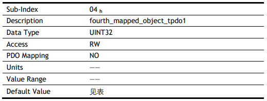
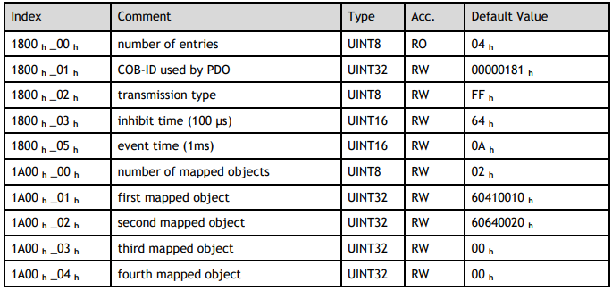
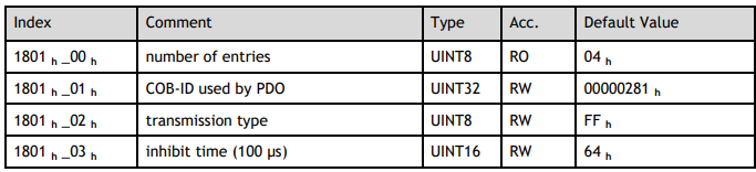
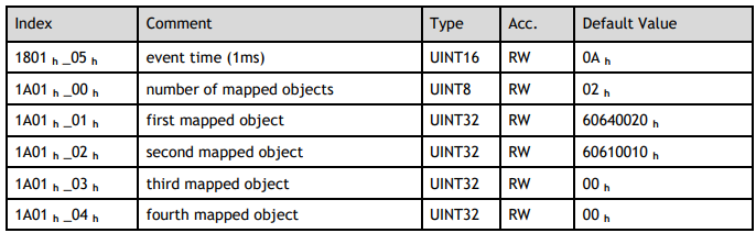
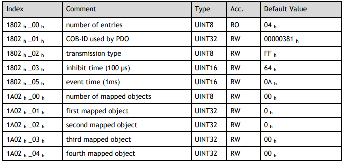
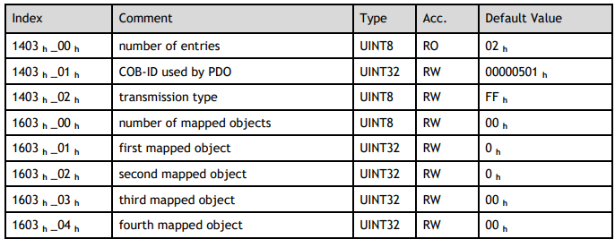
Drive contains 4 transmit PDOs and 4 receive PDOs. The detailed communication parameter and mapping parameter of the first transmit/receive PDO is as below and those of the rest 3 transmit/receive PDO are the same as the first PDO.


T-PDO1
T-PDO2
T-PDO3
T-PDO4
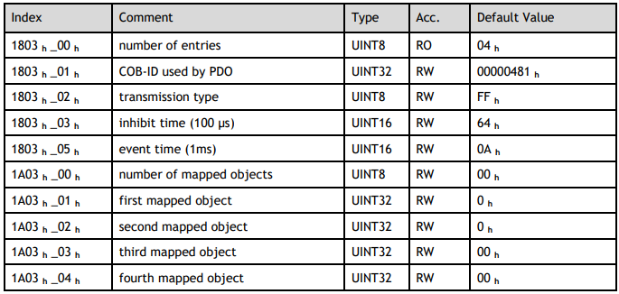
If transmit type is 254 (if PDO content has changed, such PDO is triggered to send), use of the following object can shield parts of PDO changers. Only when the un-shield bit has changed, PDO occurs. If you want shielding any bit, the corresponding bit of object write to 0.
tpdo_1_transmit_mask

tpdo_2_transmit_mask

tpdo_3_transmit_mask

tpdo_4_transmit_mask

R-PDO1
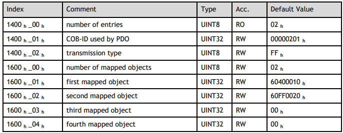
R-PDO2
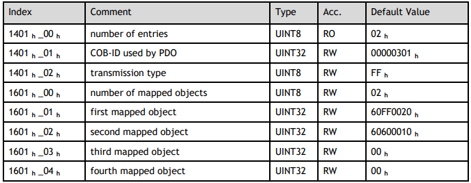
R-PDO3
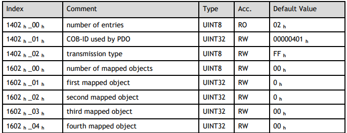
R-PDO4
6.2.4 SYNC Message
Synchronization object is used for controlling data synchronize transmit. For example, starting synchronously several axes. The transmission of synchronous message is based on Producer Customer model.
All the nodes of synchronous PDO can receive (at the same time) the message as customer and synchronize other node.
No comments to display
No comments to display