
7. Trial Operation
7.1 Preparations for Trial Operation
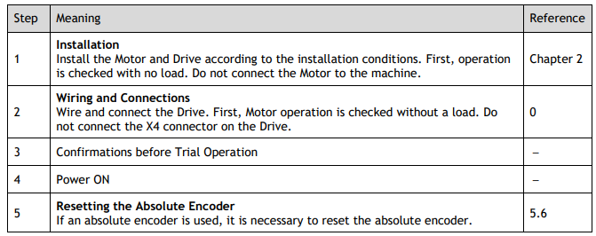
The procedure for trial operation is given below.
7.2 Inspections and Confirmations
To ensure a safe and correct trial operation, check the following items before you start trial operation.
⚫ Make sure that the Drive and Motor are installed, wired, and connected correctly.
⚫ Make sure that the correct power supply voltage is supplied to the Drive.
⚫ Make sure that there are no loose parts in the Motor mounting.
⚫ If you are using a Motor with an Oil Seal, make sure that the oil seal is not damaged. Also make sure that oil has been applied.
⚫ If you are performing trial operation on a Motor that has been stored for an extended period of time, make sure that all Motor inspection and maintenance procedures have been completed.
⚫ If you are using a Motor with a Holding Brake, make sure that the brake is released in advance. To release the brake, you must apply the specified voltage of 24 VDC to the brake, for details see the section 3.6.4 Holding Brake Wiring.
7.3 Motor Operation without a Load
You use jogging for trial operation of the Motor without a load.
Jogging is used to check the operation of the Motor without connecting the Drive to the host controller.
The Motor is moved at the preset jogging speed.

7.3.1 Preparations
Always check the following before you execute jogging.
⚫ The main circuit power supply must be ON.
⚫ There must be no alarms.
⚫ The Servo must not be in Safe State.
⚫ The servo must be OFF.
⚫ The jogging speed must be set considering the operating range of the machine.
7.3.2 Applicable Tools
⚫ Use the Panel Operator of the Drive
⚫ Use Motion Perfect V5.3 or above (Recommended)
7.3.3 JOG Operation
Use the Panel Operator of the Drive
Before performing the JOG operation by using the Panel Operator, you shall check and set the relevant parameters properly.
For the method of checking and setting parameters by using the Panel Operator, refers to the section 4.1.4 Parameter Setting Mode
Functions can be selected or adjusted by setting parameters. There are two types of parameters.
⚫ Function Parameters: the functions allocated to each digit of the Panel Operator can be selected.
⚫ Adjustment Parameters: a parameter is set to a value within the specified range of the parameter.
For a description of the parameter settings, please refer to the section Chapter 1
Function Parameters Setting
The example below shows how to change parameter Pn003 (Application Function Selections 3) from 0000 to 1032.
Step 1 Press [M] key several times to select the Parameter Setting Mode.
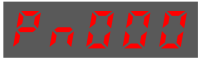
Step 2 Press [▲] key or [▼] key to select the parameter Pn003.
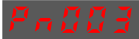
Step 3 Press [◄] key to display the current value of Pn003.
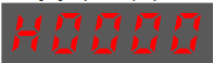
Step 4 Press and hold [◄] key for 1 second or more, and then a flashing decimal point will appear at the bottom right of the 5th digit.

Step 5 Press [▲] key twice, changing the value of the 5th digit from 0 to 2.
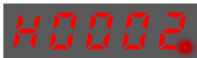
Step 6 Press [◄] key once, moving the flashing decimal point to the 4th digit.

Step 7 Press [▲] key three times, changing the value of the 4th digit from 0 to 3.
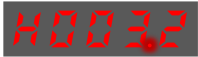
Step 8 Press [◄] key twice, moving the flashing decimal point to the 2nd digit.
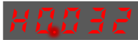
Step 9 Press [▲] key once, changing the value of the 2nd digit from 0 to 1.
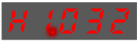
Step 10 Press and hold the [] key for 1 second or more to return to the display of the Pn003 parameter value or press the [M] key to return to the display of the Pn003.
----End

Adjustment Parameters Setting
The example below shows how to change parameter Pn102 (Speed Loop Gain) from 100 to 85.
Step 1 Press [M] key several times to select the Parameter Setting Mode.
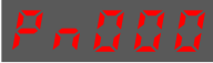
Step 2 Press [▲] key or [▼] key to select the parameter Pn102.
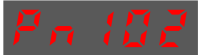
Step 3 Press [◄] key to display the current value of Pn102.
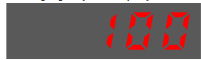
Step 4 Press [▲] key or [▼] key to change the value to 00085.
Press and hold [▲] key or [▼] key to jump the setting value quickly.

Step 5 Press [◄] key or [M] key to return to the display of Pn102.
----End
IMPORTANT
Panel Operator can only display 5 digits. The value of some adjustment parameters will be 6 digits or more. The display of the parameter values is as follows (take the display of parameter value -41943040 as an example).
The example below shows how to change parameter Pn504 (Deviation Counter Overflow Alarm) from
41943040 to 42943240.
Step 6 Press [M] key several times to select the Parameter Setting Mode.
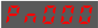
Step 7 Press [▲] key or [▼] key to select the parameter Pn504.
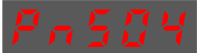
Step 8 Press [◄] key to display the bottom four digits of the current value of Pn504.

Step 9 Press and hold [◄] key for 1 second or more, and then a flashing decimal point will appear at the bottom right of the 5th digit.
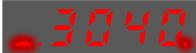
Step 10 Press [◄] key twice, moving the flashing decimal point to the 3rd digit.
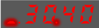
Step 11 Press [▲] key twice, changing the value of the 3rd digit from 0 to 2.
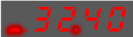
Step 12 Press [◄] key four times, moving the flashing decimal point to the 3rd of middle four digits.
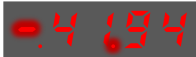
Step 13 Press [▲] key once, changing the value of the 3rd digit from 1 to 2.
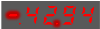
Step 14 Press and hold [◄] key for 1 second or more to return to the display of the Pn504 parameter value or 8press the [M] key to return to the display of the Pn504.
----End
7.5.6 Monitor Mode
The Monitor Mode can be used for monitoring the reference values, I/O signal status, and Drive internal status.
The Monitor Mode can be selected during Motor operation.
Select Monitor Mode
The example below shows how to display the contents of monitor number Un003 (when the Motor rotates at 100).
Step 1 Press [M] key several times to select the Monitor Mode
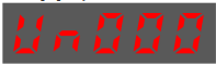
Step 2 Press [▲] key or [▼] key to select the monitor number Un003.
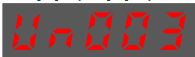
Step 3 Press [◄] key to display the data of Un003.
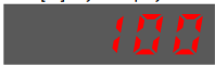
Step 4 Press [◄] key to return to the display of Un003.
The following are the steps to run the Motor between the two programmed operation patterns (PJOG0 and PJOG1).
Step 5 Press [M] key several times to select the Utility Function Mode.
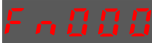
Step 6 Press [▲] key or [▼] key to select the function number Fn018.
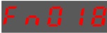
Step 7 Press [◄] key, and Panel Operator displays as below.
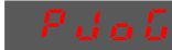
Step 8 Press [M] key to execute this operation, and Panel Operator displays as below.

Step 9 Press [◄] key to return to the display of the Fn018.
----End
No comments to display
No comments to display