
About this Manual
Purpose
This manual provides the information required for the Selection, Wiring, Connection, Settings, Trial Operation, Tuning and Functions of the DX3 Servo Drive (referred to as DX3).
Read and understand this manual to ensure correct usage of the product.
Terms and Abbreviations
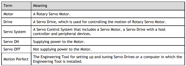
Terms that may be used in this manual are defined as follows.
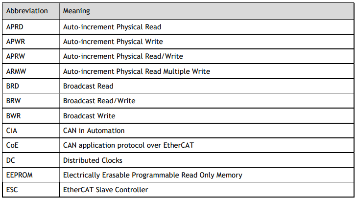
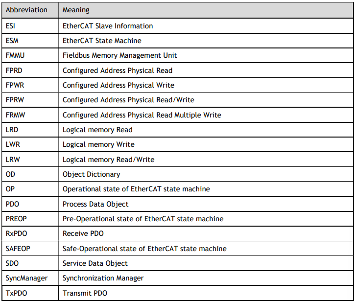
Abbreviations that may be used in describing EtherCAT or CANopen are defined as follows.
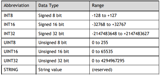
Abbreviations that may be used in describing data types and ranges are defined as follows.
Symbols
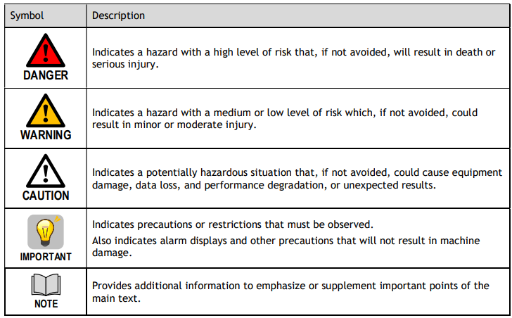
The symbols that may be found in this document are defined as follows.
The names of reverse signals (ones that are taken effect when low) are written with a forward slash (/) before the signal abbreviation. For example:
S-ON = /S-ON P-CON = /P-CON
Parameters are referenced as PnXXX where XXX refers to a unique number. Some parameters have multiple functions encoded within a single parameter. For these parameters, sub-indices are used to reference the multiple functions.
For example:
Pn112 Speed Feedforward - is a single value without any sub-indices.
Pn000 Basic Function Selection 0 - is made up of 4 sub-indexes describing different functions.
- Pn000.0 Servo ON
- Pn000.1 Forward Drive Prohibit Input (P-OT)
- Pn000.2 Reverse Drive Prohibit Input (N-OT)
- Pn000.3 Reserved parameter (Do not change)
No comments to display
No comments to display