
5. Status Display
The Status indicators on the Drive show the status of the EtherCAT network and the servo control.
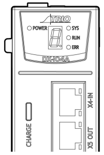
The POWER LED indicates power is present to the Control board.
The CHARGE LED indicates the voltage level on the Main circuit.
The seven-segment display shows the status of the motor control.
The LEDs integrated into the RJ45 connectors and the LEDs labeled SYS, RUN and ERR are network status indicators.
5.1 Motor Control Status Display
When the Drive is powered on the seven-segment display will show the Servo Status.
The display will cycle through a multi-digit code. The start of the sequence is the display separator, a hyphen and the decimal point. This is followed by a 2 or 3 digit code, each digit is displayed for 1 second and this sequence will continually cycle. For example, if the status is showing:
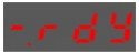
Then the sequence would be:

Some states have additional information; for example, if the drive has an active alarm, the sequence would be:

This shows the state as Servo Alarm State (FLt) and the alarm code (A01) each separated by the display separator.
5.1.1 Code
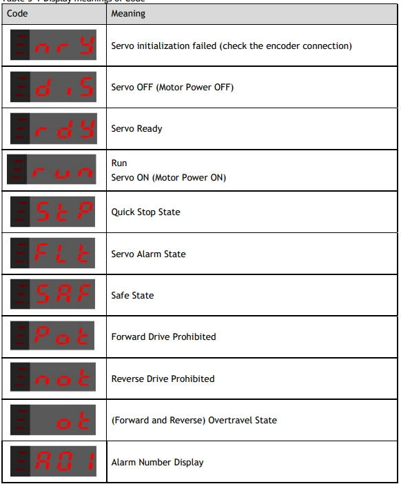
The table below described the different Code sequences shown on the Drive.
Table 5-1 Display meanings of Code
5.2 Network Status Indicators
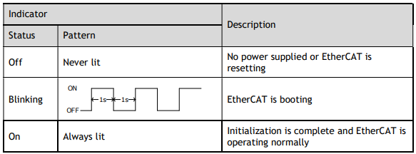
There are 3 indicator lamps on the panel Operator of the Drive to indicate the communication status of EtherCAT: SYS, RUN and ERR.
SYS Indicator
The SYS indicator shows the system status of EtherCAT communications.
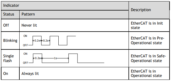
RUN Indicator
The RUN indicator shows the status of EtherCAT communications.
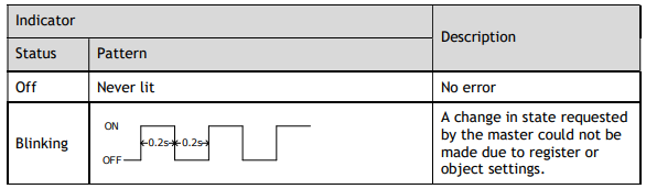
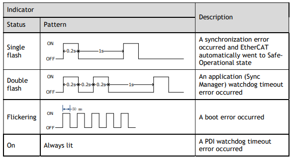
ERR Indicator
The ERR indicator shows the error status of EtherCAT communications.
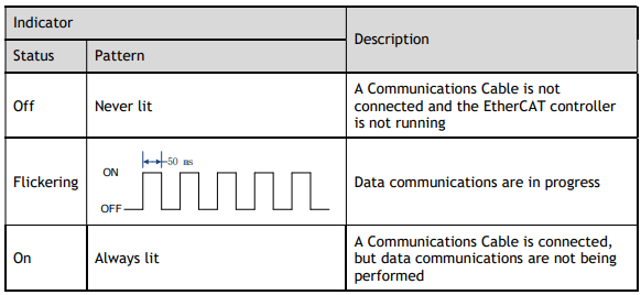
5.2.1 RJ45 LEDs
The Link/Activity indicators show whether Communications Cables are connected to the X4-IN and X5-OUT connectors and whether communications are active.
No comments to display
No comments to display