
6. IEC 61131-3 PROGRAMMING
IEC 61131-3 and Motion Perfect
This help file covers program using IEC 61131 languages using Trio Motion Technology’s Motion Perfect v3 application when used in conjunction with a compatible Trio 4 range of Motion Coordinator. The system supports several of the IEC 61131-3 defined languages providing both editing and debugging support.
Controller and Project Trees
IEC 61131 tasks are shown in the Controller and Project trees on the same level as a TrioBASIC program. This is because each represents an executable item which runs on a single controller process. All programs and spy lists in a task are shown as sub-items to the task in the tree.
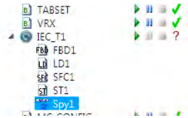 The tree items have context menus to allow the user to perform associated operations.
CONTEXT MENUS
IEC TASK
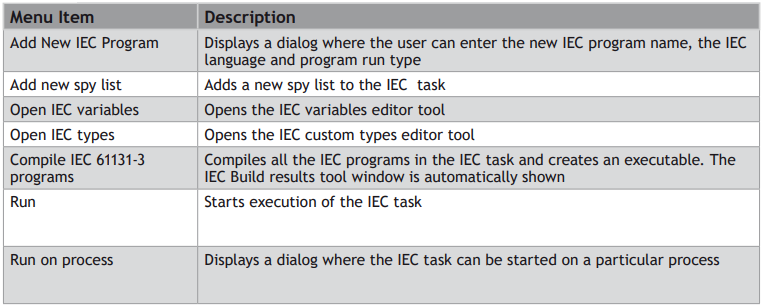
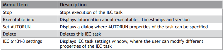
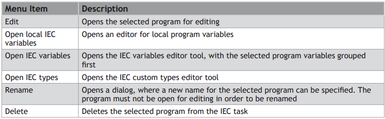
IEC PROGRAM
IEC SPY LIST

DOUBLE CLICK ACTION
Double clicking on any IEC program or Spy List in the tree will open it for viewing or editing.
Languages
Motion Perfect v3 supports the following IEC 61131-3 defined languages:
• Ladder Diagram (LD)
• Structured Text (ST)
• Function Block Diagram (SFD)
• Sequential Function Chart (SFC)
Each of the languages has its own editor and can interact with the IEC 61131 environment shared between all programs running on the sane IEC 61131 task.
The IEC 61131 Environment
TASKS
Trio 4 range of Motion Coordinators run programs in a pre-emptive multitasking environment with a limited number of processes. Normally IEC 61131 programs run on a single process (called a task) although it is possible to run more than one task in which case one process per task is used. Each task has its own IEC environment which holds “Task Variables” for that task.
VARIABLES
IEC variables are defined as “Local” which only apply to a single program or “Task” which apply to all the variables in a task.
“Task Variables” are not shared between different tasks. IEC 61131 programs which need to share
“Task Variables” must all be run in the same task.
Run all IEC 61131 programs should be run in the same task unless there is a compelling reason to do otherwise.
During debugging variables can be monitored using task based “Spy Lists”, more than one of which can be defined for the each task.
COMPILATION
When an IEC 61131 program is compiled, all the programs in that task are compiled into a single executable entity which can be executed on the controller and controlled using the usual Motion Perfect RUN/STOP/ AUTORUN etc. functionality.
Adding a New IEC 61131 Program
ADDING VIA THE “ADD NEW PROGRAM” MENU
A new IEC 61131 program can be added to a Motion Perfect project in one of two ways:
1. From the context menu associated with the “Programs” item in the Controller or Project tree, select “New...”
1. From Program main menu, select “New Program...”
The “Add New Program” dialog will be displayed.
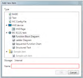
If IEC 61131 task is selected, this will add a new empty IEC task to the project.
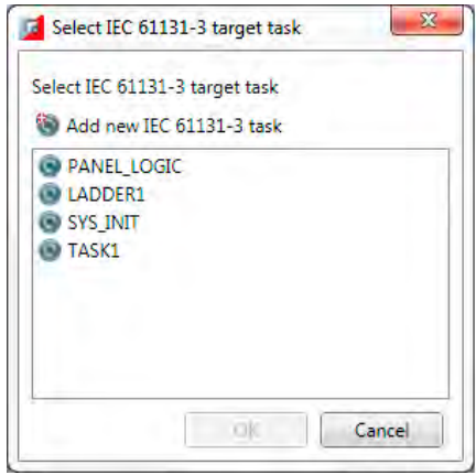
If one of the IEC 61131 program types is selected the “Select Task” dialog is displayed.
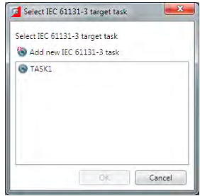
This allows the user to create the program on an existing task (by selecting the task from the list) or a new one (by clicking the “Add New” button).
After selecting a task an closing the dialog the “Add Program” dialog will be displayed.
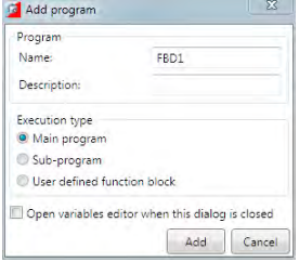
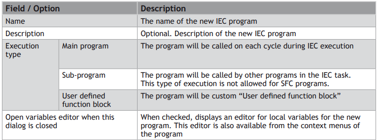
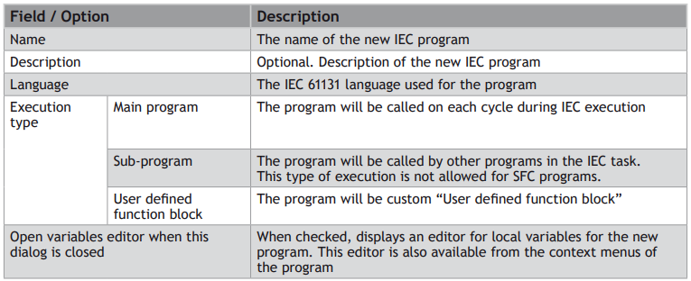
The fields and options in this dialog are as follows:
ADDING TO AN EXISTING IEC 61131 TASK
To add a program to an existing IEC task right click on the task in the Controller or Project tree. This will display the “Add Program” dialog.
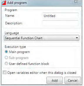
The fields and options in this dialog are as follows:
Editing Programs
To Edit an IEC program; double click on its entry in the Controller or Project Tree.
All IEC editors support standard edit operations, like CUT,COPY and PASTE. All of the editors support printing, which is available from the toolbar buttons.
When editing a larger program, it is sometimes useful to mark some pieces of code, so the user can easily navigate through the program. For this purpose, all IEC editors support Bookmarks.
All editors also support Find and Replace functionality. Find and replace window is accessible by pressing the “Ctrl+F” key combination on the keyboard.
All of the editors support drag and drop operations( from other IEC editors, from the variables tool and from spy lists ). All of the editors, except SFC editor, support drag and drop of function blocks from the toolbox.
For information on editing a specific type of IEC program see one of the following:
• Editing ST Programs
• Editing LD Programs
• Editing FBD Programs
• Editing SFC Programs
Editing LD Programs
IEC 61131-3 LD language is a graphical programming language. Ladder logic is a programming language that represents a program by a graphical diagram based on the circuit diagrams of relay logic hardware.
The language itself can be seen as a set of connections between logical checkers (contacts) and actuators (coils). If a path can be traced between the left side of the rung and the output, through asserted (true or “closed”) contacts, the rung is true and the output coil storage bit is asserted (1) or true. If no path can be traced, then the output is false (0) and the “coil” by analogy to electro-mechanical relays is considered “deenergized”.
Ladder logic has contacts that make or break circuits to control coils.
Each rung of ladder language typically has one coil at the far right.
—( )— A regular coil, energized whenever its rung is closed.
—[ ]— A regular contact, closed whenever its corresponding coil or an input which controls it
The “coil” (output of a rung) may represent a physical output which operates some device connected to the controller, or may represent an internal storage bit for use elsewhere in the program.
Double-clicking on a contact or a coil displays a dialog for selecting the input/output for the element.
Double-clicking on a function/function block displays a dialog for selecting the function/functional block for the element.
The editor contents can be zoomed in and out via the toolbar buttons, or using the shortcut combinations “Ctrl +” for zoom in and “Ctrl -” for zoom out.
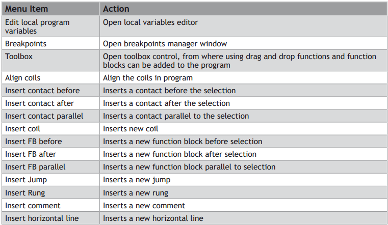
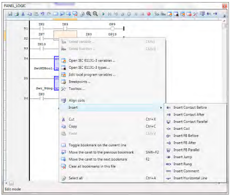
The LD editor context menu has the following functionality:

Editing ST Programs
IEC 61131-3 ST language is a text-based programming language. It supports most of the traditional procedural programming language paradigms. t is a high level language that is block structured and syntactically resembles Pascal. All of the languages share IEC 61131 Common Elements. The variables and function calls are defined by the common elements so different languages can be used in the same program.
Complex statements and nested instructions are supported:
• Iteration loops (REPEAT-UNTIL; WHILE-DO)
• Conditional execution (IF-THEN-ELSE; CASE)
• Functions (SQRT(), SIN())
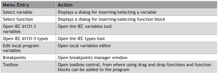
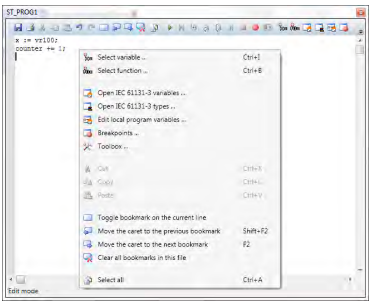
The ST editor’s context menu has the following commands:
Editing FBD Programs
IEC 61131-3 FBD language is a graphical programming language. The FBD editor is a powerful graphical tool that enables you to enter and manages Function Block Diagrams according to the IEC 61131-3 standard.
The editor supports advanced graphic features such as drag and drop, object resizing and connection lines routing features, so that you can rapidly and freely arrange the elements of your diagram. It also enables you to insert in a FBD diagram graphic elements of the LD (Ladder Diagram) language such as contacts and coils
A functional block diagram is a block diagram that describes a function between input variables and output variables. A function is described as a set of elementary blocks. Input and output variables are connected to blocks by connection lines. An output of a block may also be connected to an input of another block: Inputs and outputs of the blocks are wired together with connection lines, or links. Single lines may be used to connect two logical points of the diagram:
An input variable and an input of a block
An output of a block and an input of another block
An output of a block and an output variable
The connection is oriented, meaning that the line carries associated data from the left end to the right end. The left and right ends of the connection line must be of the same type.
Double-clicking on a contact or a coil displays a dialog for selecting the input/output for the element.
Double-clicking on a function/function block displays a dialog for selecting the function/functional block for the element.
The editor contents can be zoomed in and out via the toolbar buttons, or using the shortcut combinations “Ctrl +” for zoom in and “Ctrl -” for zoom out.
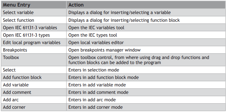
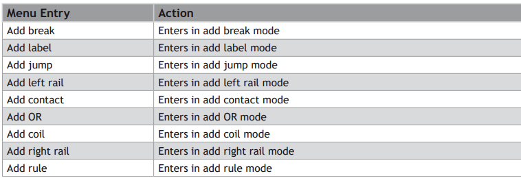
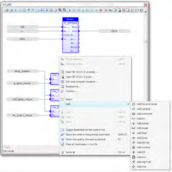
The FBD editor context menu has the following functionality:
Editing SFC Programs
IEC 61131-3 SFC language is a graphical programming language. Main components of SFC are:
• Steps with associated actions
• Transitions with associated logic conditions
• Directed links between steps and transitions
Steps in an SFC diagram can be active or inactive. Actions are only executed for active steps. A step can be active for one of two motives: (1) It is an initial step as specified by the programmer (2) It was activated during a scan cycle and not deactivated since
The editor contents can be zoomed in and out via the toolbar buttons, or using the shortcut combinations “Ctrl +” for zoom in and “Ctrl -” for zoom out.
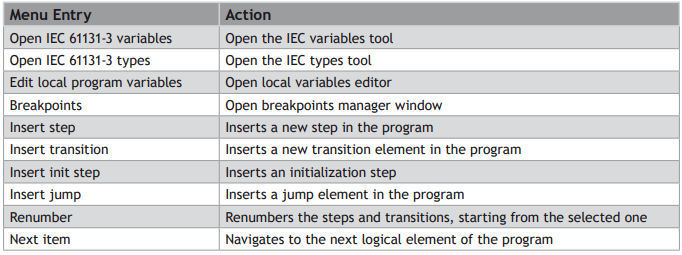
The SFC editor context menu has the following functionality:
SFC programs are divided into 2 levels:
LEVEL 1
level 1 is the main SFC chart, which describes the steps and transitions and is edited by the SFC editor.
A step represents a stable state. It is drawn as a square box in the SFC chart. At runtime a step can be either active or inactive. All actions linked to the steps are executed depending on the activity of the step. Initial steps represent the initial situation of the chart when program is started. There must be at least one initial step in each SFC chart.They are marked with a double line.
Transitions represent a condition the changes the program activity from one step to another. It is marked by a small horizontal line that crosses a link drawn between the two steps. The condition must be a BOOL expression. Transitions define the dynamic behaviour of the SFC chart, according to the following rules:
A transition in crossed if:
• its condition is TRUE.
• and if all steps linked to the top of the transition (before) are active.
When a transition is crossed:
• all steps linked to the top of the transition (before) are de-activated.
• all steps linked to the bottom of the transition (after) are activated.
DIVERGENCES
It is possible to link a step to several transitions and thus create a divergence. The divergence is represented by a horizontal line. Transitions after the divergence represent several possible changes in the situation of the program.
All conditions are considered as exclusive, according to a left to right priority order. It means that a transition is considered as FALSE if at least one of the transitions connected to the same divergence on its left side is TRUE
LEVEL 2
level 2 is the code for the actions, transitions and text for notes for level 1 elements
Each level 1 step has 5 level 2 elements, which can be open for editing by double-clicking on the corresponding element.
1. Actions – Simple actions entered as text
2. P1 actions, that can be programmed in ST,LD or FBD, are executed only once when the step becomes active
3. N actions, that can be programmed in ST,LD or FBD, are executed on each cycle while the step is active
4. P0 actions, that can be programmed in ST,LD or FBD, are executed only once when the step becomes inactive
5. Text notes
While a level 2 item is open for editing, the contents of the parent level 1 SFC program is locked for editing. This is done to prevent renumbering or deleting of the parent level 1 element, for which the level 2 editor is open. Once the editing of the level 2 element is complete, and the user closes the child editor, the SFC editor is unlocked and its normal operation is restored.
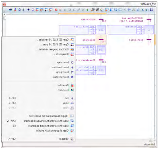
When editing a level 2 SFC program, an additional combo box will appear in the status bar of the program editor

From this combo box the language of the level 2 element can be chosen. The default is ST. When the language is changed, a prompt will appear, notifying that the current contents of the program will be cleared.
IEC Types Editor
The types editor tool is an editor, where the user can define, delete and modify custom types. It is a tab panel, which has 3 tabs : one for the IEC structures, one for the IEC enumerated types and one for the IEC bit fields.
STRUCTURES TAB
The structures tab displays the custom structure types:
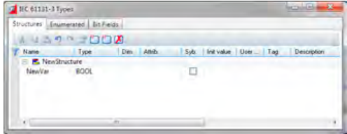
The description of the fields available for editing is the same as for the variables editor tool.
To add a new structure, press the “Insert new structure” button. To delete an existing structure, select it and press the “Delete” key on the keyboard, or press the “Remove” button.
Double-click on a selected structure displays the “Type properties” dialog, where a type name, comment and description can be edited.
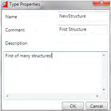
To add a new field in an existing structure, press the “Insert” key on the keyboard, or press the “Insert new variable” button. To delete an existing field in a structure, select it and press the “Delete” key on the keyboard, or press the “Remove” button.
ENUMERATED TAB
The enumerated tab displays the custom enumerated types:
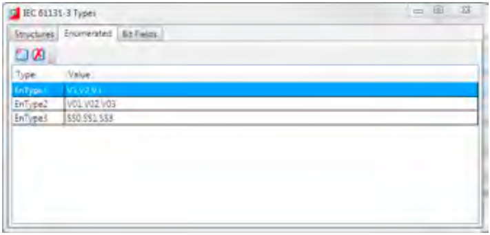
This tab editor has 2 columns:

To add a new enumerated type, press the “Add new IEC type” button. To remove an existing enumerated type, select it and press the “Remove” button.
To edit the name of an existing enumerated type, double-click on the selected type’s Name column in the editor.
To edit the enumerated values, double-click on the selected type’s Value column.
1. BIT-FIELDS TAB
The bit-fields tab displays the custom bit-field types:
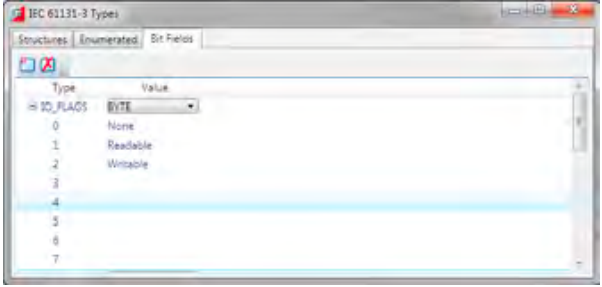
This tab editor has 2 columns:
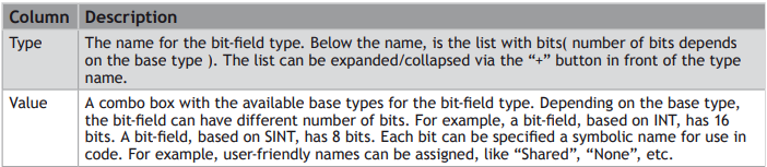
To add a new bit-field type, press the “Add new IEC type” button. To remove an existing bit-field type, select it and press the “Remove” button.
To edit the name of an existing bit-field type, double-click on the selected type’s Type column in the editor.
To change the base type of the selected bit-field type, use the combo box with available types.
To edit the bit-field names, double-click on the selected bit-field bit in the value column.
Program Local Variables
All IEC programs have local variables, which are “private” to the programs only. User defined function block programs, have also input and output variables, which are also local program variables.
The editor for the local variables, provides an easy way of adding/removing and setting properties of local variables.

For normal IEC programs, only the “Private variables” are available. For FBD programs additional sections for “Input Variables” and “Output Variables” are available.
Variable Editor
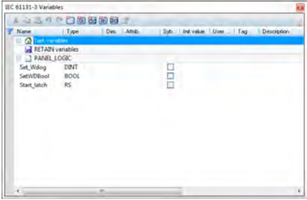
The Variable Editor displays all the variables that are in use in the IEC task. The variables are grouped in variables groups. There are 2 predefined variables groups – the “Task” and “Retain” variables. Then for each IEC program in the IEC task, a variable group with the same name as the program exists.
Variables in the “Task” group are accessible from all programs. The values of the variables in the “Retain” group are stored upon IEC execution stop and are restored upon next start of the IEC executable. The variables in the rest of the groups are “private” for the corresponding program.
A new variable can be added, by selecting the corresponding group, and pressing the “Insert” key on the keyboard. A new variable will be inserted in the selected group and will have default name, type, initial value, etc.
The variable has the following properties, which are separated as columns in the variables editor:
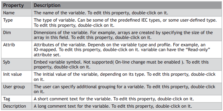
Each variable has a set of properties attached. The properties editing dialog is displayed, when a variable is selected and the properties toolbar button is pressed, of from the context menu for the selected variable.
VARIABLE PROPERTIES EDITING
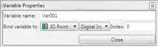
The Variables Properties dialog provides an editable text box, where the user can change the name of the variable and its mapping (if any) physical memory or I/O on the controller, by selecting one of the binding methods.


Selecting or Inserting a Variable
This applies to ST, LD and FBD programs.
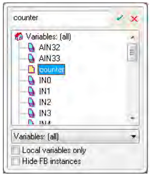
When the “Select variable” command is chosen from the context menu, a popup dialog appears in which the user can select an existing variable to replace the variable in the current selection, or to create a new variable. Type the name of the variable into the edit box and, if the variable already exists in the current scope, it will be selected. Pressing the Enter key, or the small green check on the dialog will replace the variable with the selected one. If a variable with the typed name does not already exist, a prompt will appear for creating this variable, setting its type and group.
Selecting or Inserting a Function Block
This applies to ST, LD and FBD programs.
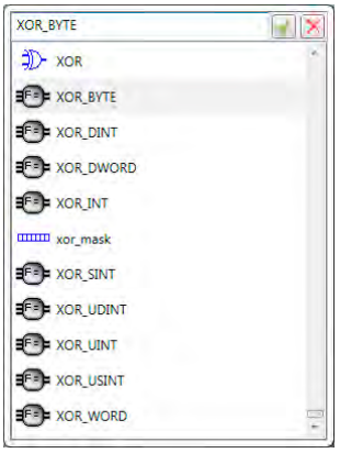
When the “Select function” command is chosen from the context menu, a popup dialog appears, where the user can select from a list of available functions and function blocks. Type the name or symbol of the function/function block into the edit box and if it exists, it will be selected in the list. Pressing the Enter key or the small green check box will replace/insert the selected function in the editor with the selected one from the list box.
Compiling
When the “Build” command is executed, the “IEC 61131-3 Compilation” tool is automatically displayed. It contains a list with the build results from compiling the IEC task into an executable.
If the project compilation have been successful, there should be no errors, and the executable is downloaded on the controller.
If any errors occurred, the error description is displayed as a hint, so the error can be removed by the user.
Double-clicking on an item opens the source editor, relevant to the item. In the example below, doubleclicking on the second line( Variable, constant expression or function call expected), will open an editor for the “LADDER1” program, and will position the caret on line 1, column 9 (which is the source of the error).
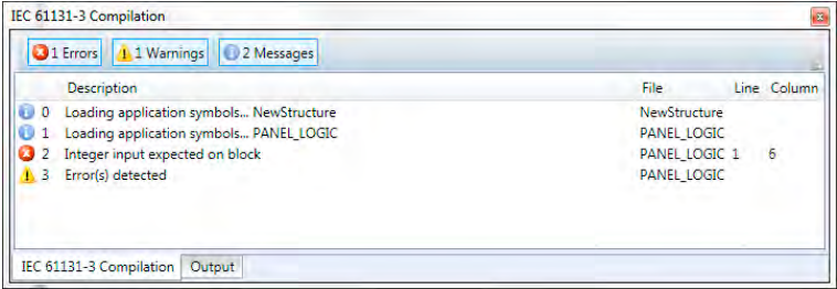
To show and hide different types of messages, the user can use the “Errors”, “Warnings” and “Messages” buttons respectively.
Running and Debugging a Program
When an IEC task is compiled, it can be executed by several ways:
1. From the toolbar of the IEC item in the project tree
2. From the context menu of the IEC item in the project tree
3. From the toolbar of some of the IEC programs, belonging to that IEC task
4. From the command line, by typing “RUN ”
5. From a BASIC program, using RUN basic command
It is possible that an IEC task can be started more than once (e.g. from a BASIC program) but this is not a typical scenario. Motion Perfect’s support for IEC programs is designed in a way that only one instance of an IEC task can be debugged at a time. Different IEC tasks can be debugged simultaneously, however, when connecting to a controller with more than one instance of the same IEC task running, Motion Perfect will prompt to which instance the debugger should connect.
It is also possible to set an IEC task to automatically start when the controller boots up, from the context menu of the IEC task, selecting the command “Set AUTORUN”, or using the standard command RUNTYPE.
Spy List window
A spy list window can be opened for each spy list, defined in the IEC task by double-clicking on the spy list in the project tree, or from its context menu.
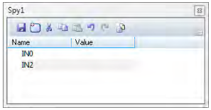
The Spy List is a list of variables and their values:

To add a new variable directly to the list of variables, drag and drop from an open editor, or the variables editor, or the structures editor. Alternatively press the “Insert” key on the keyboard or click on the Add Variable button in the toolbar, which will pop-up a dialog allowing the user to select the variable from a list.
To remove a variable from the list, select the variable, and press the “Delete” key on the keyboard.
As spy lists are part of the IEC task, when variables are added to, or removed from a spy list, the IEC task has to be recompiled.
IEC Settings
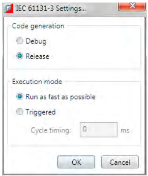
The IEC Settings dialog can be accessed from the context menu of task in the Controller or Project Tree. It allows the user to adjust what type of code is generated and how it is run.
CODE GENERATION
The Code Generation setting controls which type of code is produced:
• Debug Code: allows the user to use Spy Lists to view variables and to step through the code in order to debug it. The generated code is larger and will run more slowly than the release code.
• Release Code: contains no debugging information.
EXECUTION MODE
This determines how the code is executed:
• Run as fast as possible: Cycles are executed with the fastest possible speed of the hardware platform.
• Triggered: Cycles are executed with respect to the specified cycle time. The cycle time is the time between 2 consecutive cycles, in milliseconds. If for example, the user wants to execute code twice each second, the cycle timing should be specified as 500 ms( here the time needed for executing the instructions is ignored. In real-world scenarios, more precise timing might be needed )
No comments to display
No comments to display