
3. Wiring
3.1 Main Circuit Wiring
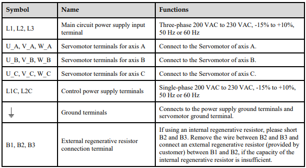
3.1.1 Names and Functions
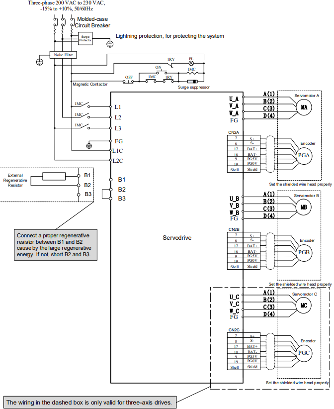
3.1.2 Wiring Example
3.2 Inputs and Outputs
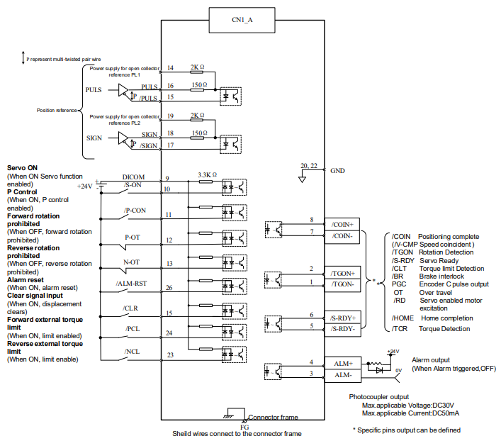
3.2.1 Wiring Example

3.2.2 Terminal Layout
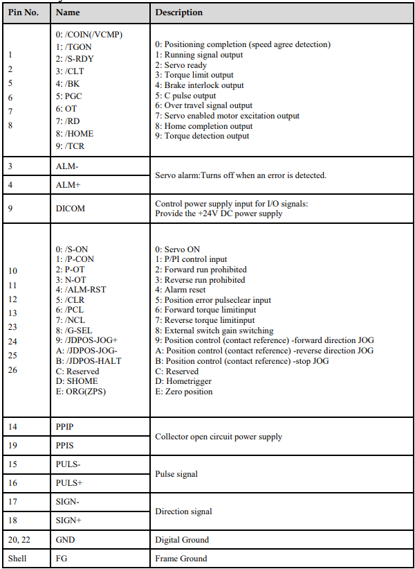

3.2.3 Names and Functions
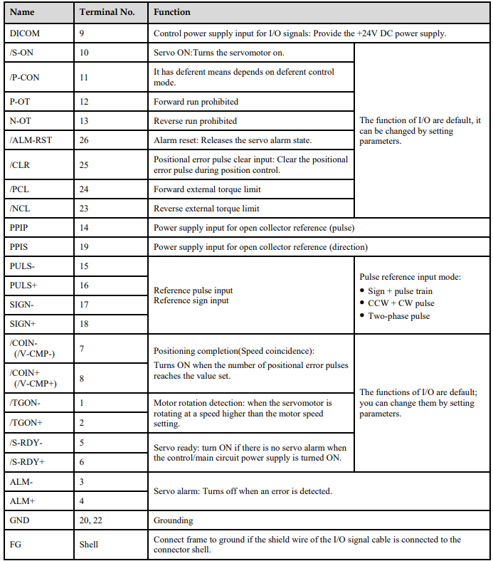
3.2.4 I/O Circuits
Sequence Input Circuits
Examples for Relay Circuits and Open-Collector Circuits are as shown in the following figure
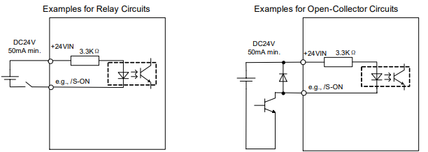
Select a low-current relay for the relay circuits, or a faulty contact may be caused
Encoder Output Circuits
The signals of the encoder pulses (PAO+, PAO-, PBO+, PBO-) and origin signal pulses (PCO+, PCO-) are output by the bus drive circuits. The circuits are usually used in the host controller for forming a position control system, which connects a encoder output circuit to line-receiver circuit.
For details ahout the encoder circuit, see the section 3.3 Encoder Wiring.
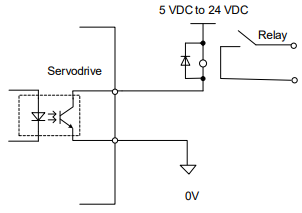
Sequence Output Circuits
Photocoupler output circuits are used for the ALM (Servo Alarm), /P-CON (Position Complted), /BK (Brake Interlock) and other sequence output signals.

3.3 Encoder Wiring
3.3.1 Wiring Diagram
Incremental Encoder
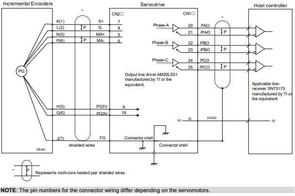
Absolute Encoder
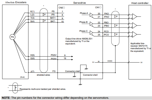
Incremental Encoder
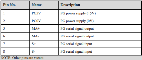
Absolute Encoder
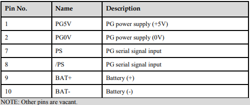
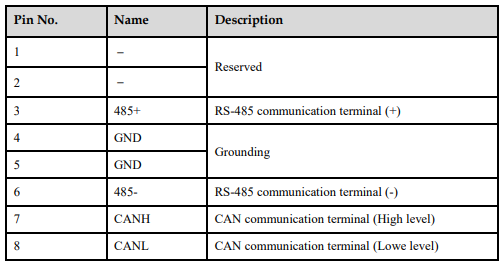
3.4 Communication Wiring
3.5 Wiring for Noise Control
3.5.1 Noise Control
The servodrive uses high-speed switching elements in the main circuit. It may receive "switching noise"from these high-speed switching elements.
To prevent malfunction due to noise, take the following actions:
Position the input reference device and noise filter as close to the Servodrive as possible.
Always install a surge absorber in the relay, solenoid and electromagnetic contactor coils.
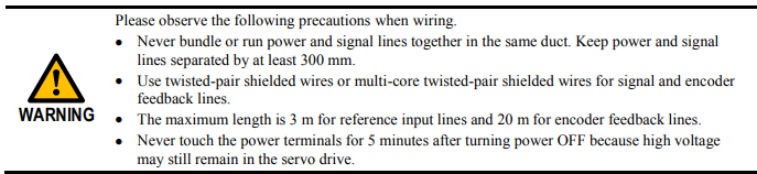
The distance between a power line (servomotor main circuit cable) and a signal line must be at least 30 cm.Do not put the power and signal lines in the same duct or bundle them together.
Do not share the power supply with an electric welder or electrical discharge machine. When the servo drive is placed near a high-frequency generator, install a noise filter on the input side of the power supplyline. As for the wiring of noise filter, see the seciton Noise Filter.
For proper grounding technique, see the section Correct Grounding.
Noise Filter
Please install a noise filter in the appropriate place to protect the servo drive from external noise interference.
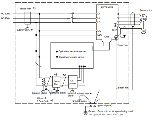
When using a noise filter, always observe the following wiring instructions:
For a ground ground wire to be connected to the casing, use a thick wire with a thickness of at least 3.5 mm2 (preferably, plain stitch cooper wire).
For wires indicated by P↕, use twisted-pair cables whenever possible.
Correct Grounding
Take the following grounding measures to prevent the servo drive from malfunctioning due to noise.
Grounding the Motor Frame
If the servomotor is grounded via the machine, a switching noise current will flow from the servo drive main circuit through the servomotor stray capacitance.
Always connect servomotor frame terminal FG to the servodrive ground terminal. Also be sure to ground the ground terminal
Noise on the I/O Signal Line
If the I/O signal line receives noise, ground the 0 V line (SG) of the reference input line. If the main circuit wiring for the motor is accommodated in a metal conduit, ground the conduit and its junction box. For all grounding, ground at one point only.
Precautions on installing on the control panel
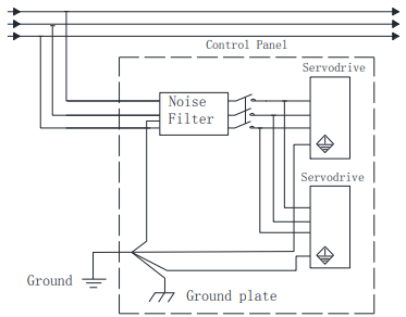
When the servo drive is installed on the control panel, a piece of metal plate should be fixed. It is used for fixing the servo drive and other peripheral devices. The noise filter should be installed on the metal plate, and closed to the hole drill through power lines on control panel. Use screws to fix the noise filter to the metal plate. The grounding terminals of noise filter connects to the grounding terminals of control panel.
Servo drive should be fixed on a piece of metal plate. Make sure the heat sink towards ground. The grounding terminals of servo drive connect to the grounding terminals of control panel.
3.5.2 Precautions on Connecting Noise Filter
Noise Filter Brake Power Supply
Use the noise filter Manufactured by SCHAFFNER at the brake power input for servomotors with holding brakes.
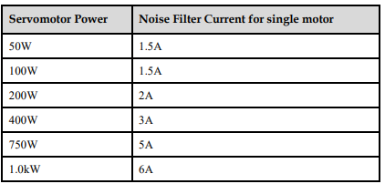
Relationship between servo drive power and noise filter current:

Precautions on Using Noise Filters
Do not put the input and output lines in the same duct or bundle them together.
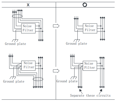
Separate the noise filter ground wire from the output lines.
Do not accommodate the noise filter ground wire, output lines and other signal lines in the same duct or bundle them together.
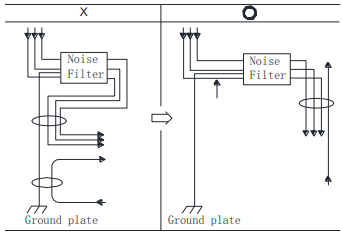
Connect the noise filter ground wire directly to the ground plate. Do not connect the noise filter ground wire to other ground wires.
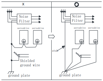
If a noise filter is located inside a control panel, connect the noise filter ground wire and the ground wires from other devices inside the control panel to the ground plate for the control panel first, then ground these wires.
No comments to display
No comments to display