
6. CANopen Communication
6.1 Wiring and Connection
The terminal layout of CN3 and CN4 is as follwing:
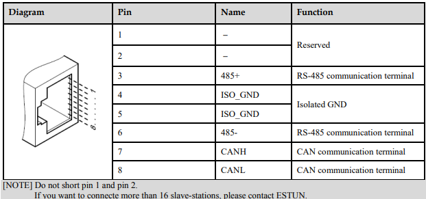
CN3 is always the input terminal of communication cable and CN4 is always the output terminal of communication cable. (If connection to another communication node is necessary, the cable will connect CN4 to next communication node. If not, a terminal resistor could be applied at CN4). When multiple ED3M devices are connected, it is forbidden to connect the CN3 terminals of different drives directly.
For example, a network is composed of one PLC, three ProNet drives called A, B and C. The cabling network is as below:
PLC → CN3 of drive A,CN4 of drive A → CN3 of drive B,CN4 of drive B → CN3 of drive C, CN4 of drive C → 120Ω resistor.
The two ends of the CAN cable have to be terminated by a resistor of 120Ω (1%, 1/4W) as below.

Please select the bus cable with double twisted pair cables and shielding layer, one pair for connecting CAN-L and CAN-H, another pair for grounding.
6.2 Messages Description
CAL supplies all network management service and message transferring protocol with defining the content of object or type of object for communication. It defines how instead of what, which is the strength of CANopen.
CANopen is developed based on CAL. It applies CAL protocol subsets for communication and service and creates a solution to DCS. CANopen could freely extend the node function to simplicity or complex while the network nodes are accessible and available to each other.
The key concept of CANopen is object dictionary. This way of object description is also applied to other fieldbus system like Profibus and Interbus-S. CANopen communication could access to all the parameter of drivers through object dictionary. Please notice object dictionary is not one part of CAL, instead of which it is realized in CANopen.
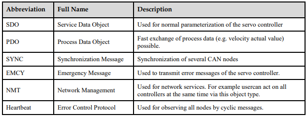
CANopen communication defines several types of objects as below
CAN employs data frames for transferring data between the host (controller) and the nodes on the bus. The following figure presents the structure of the data frame.

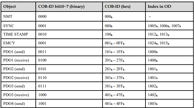
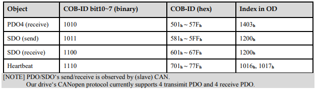
Our drivers doesn’t support remote frame currently. The detail of COB-ID is as below

6.2.1 CAN identifier list
6.2.2 SDO
SDO is used to visit the object dictionary of a device. Visitor is called client. The CANopen device whose object dictionary is visited and required to supply the asked service is called server. CANopen messages from a client and servo all contain 8 bits (Not all of them are meaningful). A request from a client must be confirmed by a server
There are 2 method of conveying SDO:
Expedited transfer: contains 4 bytes at maximum
Segmented transfer: contains more than 4 bytes
Basic structure of SDO:

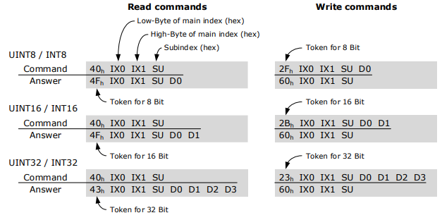
SDO read/write command structure:
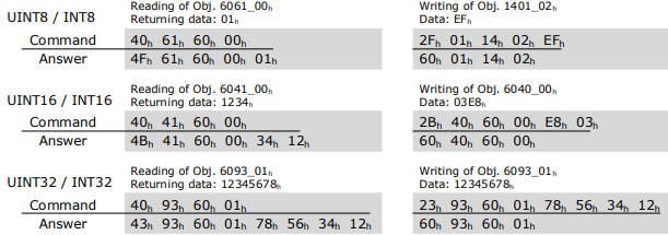
For example:
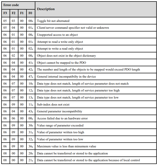
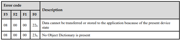
SDO-error messages:

6.2.3 PDO
PDO is applied to transferring real time data which will be conveyed from a producer to one or multiple clients. Data transferring will be limited to 1 to 8 bytes. There is no hand-shake restriction in PDO communication, which means data has been redefined, so clients could process the received data for vary short time. PDO content will be only defined by its CAN ID, assuming producers and clients know PDO content from its CAN ID.
Objects Description
Two objects in object dictionary are used for each PDO.
PDO communication parameter: It contains COB-ID, transferring type, restriction time and cycle of timer used by PDO.
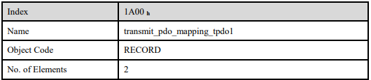
PDO mapping parameter: It contains a list of objects in the object dictionary. These objects are mapped into PDO, includes their data length in bits. Producers and clients must know this mapping to explain the content of PDO.
The content of PDO’s message is predefined or configured when the network initializes. Mapping application object into PDO is described in object dictionary. If a device (producer and client) support dynamic mapping, SDO could be used to configure PDO’s mapping parameter. Our servo drive supports dynamic PDO mapping. There are 2 rules for PDO mapping to follow.
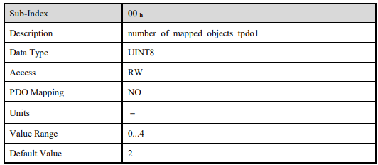
Each PDO could be mapped into 4 objects.
The length of each PDO will be no more than 64 bits.
Mapping Process
1. Set the sub-index of PDO coordinated mapping parameter (1600 h, 1601 h, 1A00 h or 1A01 h) as o.
2. Revise the sub-index from 1 to 4 of PDO coordinated mapping parameter (1600 h, 1601 h, 1A00 h or 1A01 h).
3. Set the sub-index 0 of PDO coordinated mapping parameter(1600 h ,1601 h,1A00 h or 1A01 h ) as legal number( number of PDO’s mapping objects)
4. PDO mapping was completed.
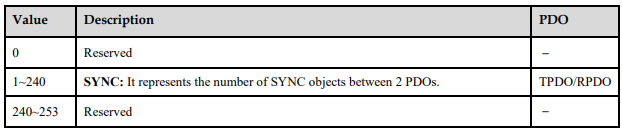
Transmit Type
Synchronous (Synchronization by receiving SYNC object)
Cycle: Transmit triggered after every 1 to 240 SYNC messages.
Asynchronous
Transmit triggered by special object event regulated in sub-object protocol.
Transmit Type List

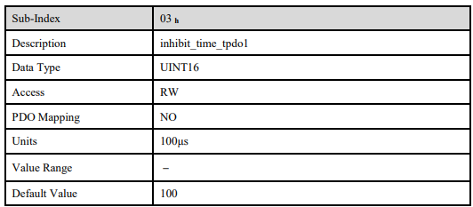
One PDO could set a frozen time which is the shortest interval time between 2 continuous PDO. It could prevent the bus from being occupied by amount of data with high priority. Frozen time is defined by 16 bit unsigned integer number and its unit is 100us.
One PDO could set a timing period. When the regulated time is violated, a PDO transmit could be
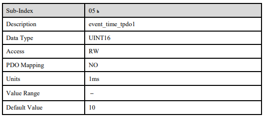
triggered without a trigger bit. Object timing period is defined as 16 bit unsigned integer and its unit is 1ms.
Mapping Case
Map the 3 objects to PDO1 (transmit). PDO1 (transmit) is required to be asynchronous periodic type with period time as much as 10ms and frozen time as much as 2ms.

1. Clear number_of_mapped_objects
number_of_mapped_objects(1A00 h: 00 h)= 0
2. Set the parameter for mapping objects
Index =6041 h Subin. = 00h Length = 10 h ⇒ 1st_mapped_object(1A00 h: 01 h)= 60410010 h
Index =6061 h Subin. = 00h Length = 08 h ⇒ 2st_mapped_object(1A00 h: 02 h)= 60610008 h
Index =60FD h Subin. = 00h Length = 20 h ⇒ 3st_mapped_object(1A00 h: 03 h) = 60FD0020 h
3. Set number_of_mapped_objects
number_of_mapped_objects(1A00 h: 00 h)= 3
4. Set PDO communication parameters
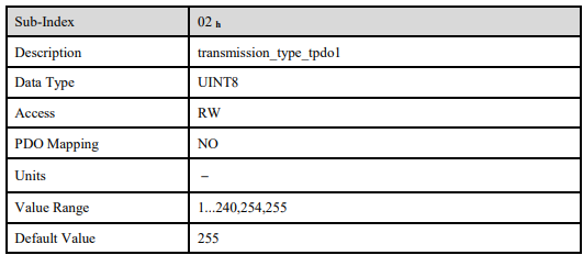
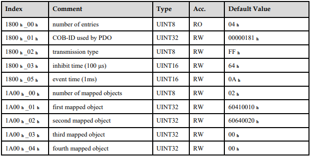
PDO1 (transmit) is asynchronous periodical type ⇒ transmission_type (1800 h: 02 h)= FF h
Frozen time 2ms(20×100us) ⇒ inhibit_time (10A0 h: 03 h)= 14 h
Period time: 10ms(10×1ms) ⇒ event_time (1800 h: 05 h)= 0A h
5. PDO mapping was completed.
PDO Parameter
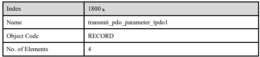
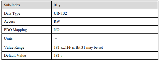
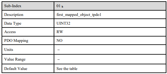
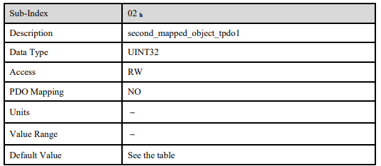
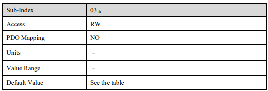
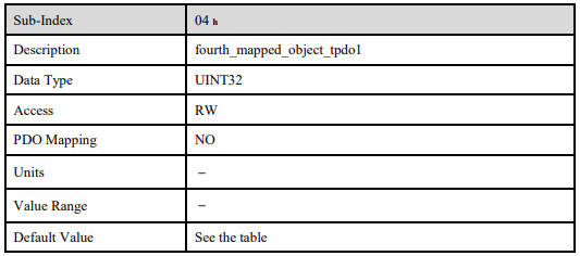
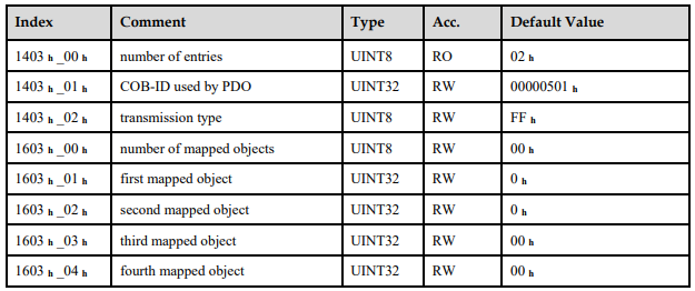
ED3M drive contains 4 transmit PDOs and 4 receive PDOs. The detailed communication parameter and mapping parameter of the first transmit/receive PDO is as below and those of the rest 3 transmit/receive PDO are the same as the first PDO.


T-PDO1
T-PDO2
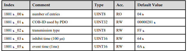
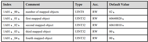
T-PDO3
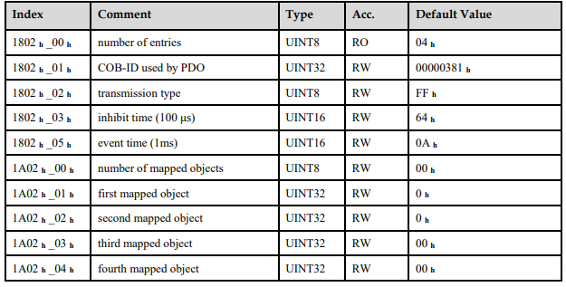
T-PDO4
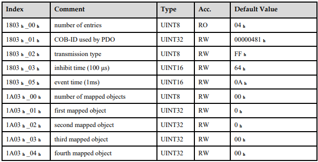
If transmit tye is 254 (if PDO content has changed,trigger will be sent by PDO),using the following object can shield parts of PDO changers.Only when the un-shield bit has changed,PDO is occur.If wants shielding any bit, the corresponding bit of object write to 0.
tpdo_1_transmit_mask

tpdo_2_transmit_mask

tpdo_3_transmit_mask
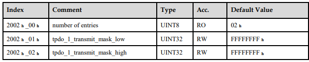
tpdo_4_transmit_mask

R-PDO1
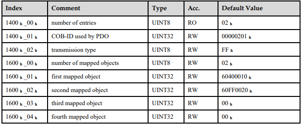
R-PDO2

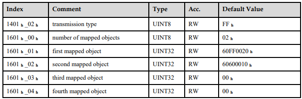
R-PDO3
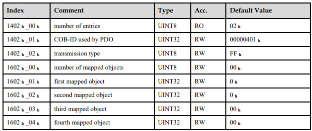
R-PDO4
6.2.4 SYNC Message
Synchronization object is used for controlling data synchronize transmit. For example: starting synchronously several axises. The transmition of synchronous message is based on Producer Customer model. All the nodes of synchronous PDO can receive (at the same time) the message as customer and synchronize other node.
CANopen suggests a COB-ID with highest priority to ensure that synchronized signal could be transmitted properly. Without transferring data, SYNC message could be as short as possible.
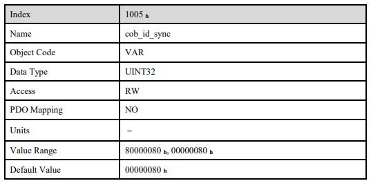
The identifier the servo controller receives SYNC messages are fixed to 080h. The identifier can be read via the object cob_id_sync.
6.2.5 Emergency Message
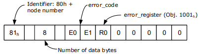
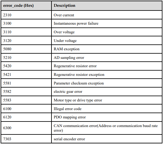
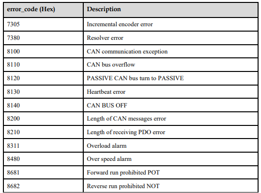
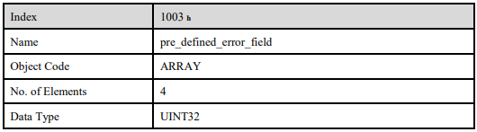
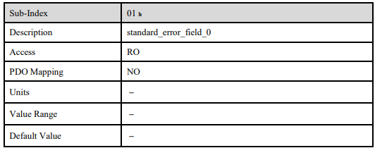
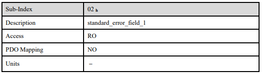
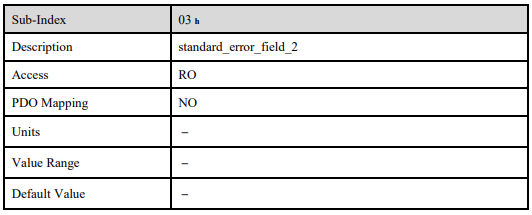
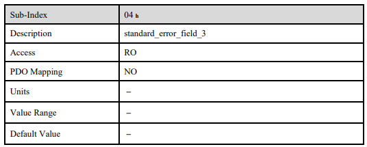
When an alarm occurs to drive, CANopen will initiate an Emergency message to inform the current drive type and error code to clients. Error code displayed on panel can be read on low byte of 603Fh object.
The structure of Emergency message:
Alarm Codes
Relevant Parameters

6.2.6 HEARTBEAT Message
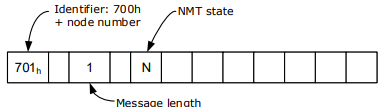
Structure
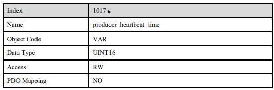
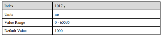
Relevant Parameter
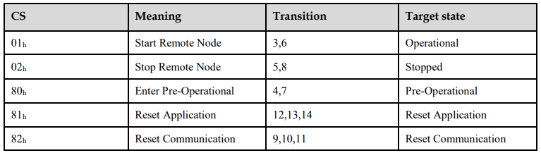
6.2.7 Network management (NMT service)
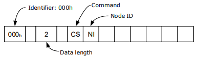
Structure
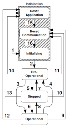
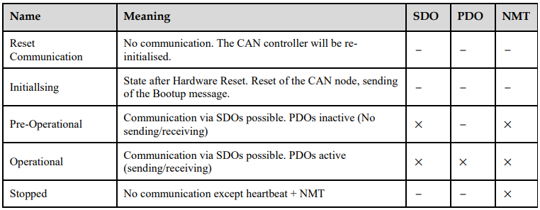
NMT-State machine

6.3 Conversion Factors (Factor Group)
Servo controllers will be used in a huge number of applications: As direct drive, with gear or for linear drives. To allow an easy parameterization for all kinds of applications, the servo controller can be parameterized in such a way that all values like the demand velocity refer to the driven side of the plant. The necessary calculation is done by the servo controller.
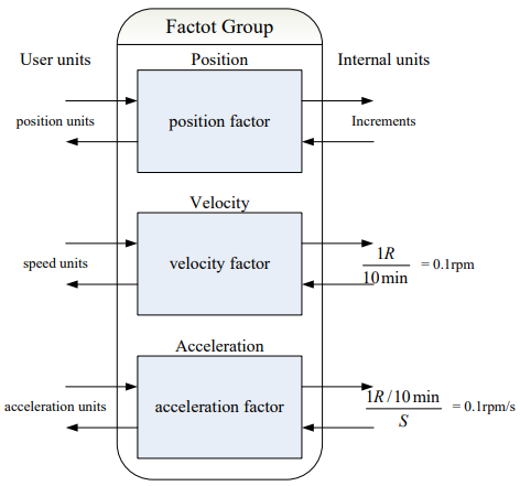
The default setting of the Factor Group is as follows:
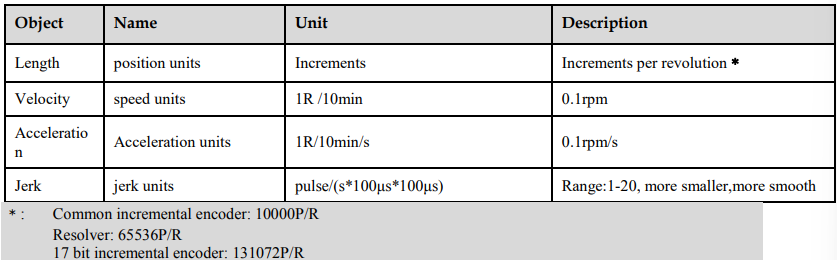

6.3.1 Relevant parameters

6.3.2 Position factor
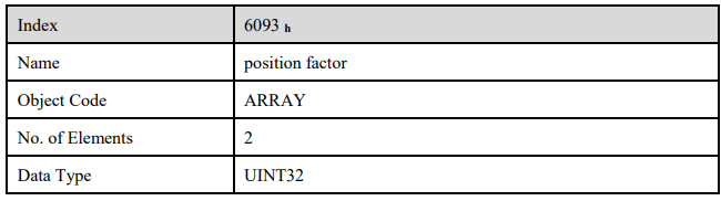
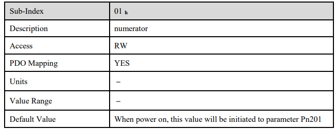
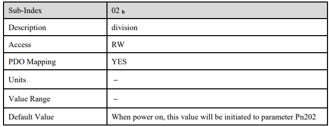
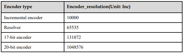
The object position factor converts all values of length of the application from Position units into the internal unit increments (encoder resolution equals 1 Revolution). It consists of numerator and divisor:
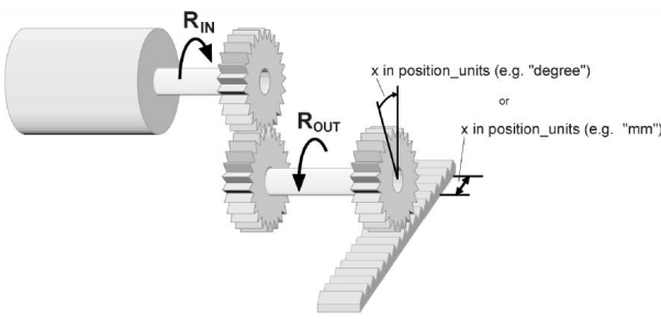
To calculate the position factor the following values are necessary:
gear_ratio
Ratio between revolutions on the driving side (RIN) and revolutions on the driven side (ROUT).
feed_constant
Ratio between revolutions on the driven side (ROUT) and equivalent motion in position_units (e.g. 1 rev = 360°)
The calculation of the position_factor is done with the following equation:

6.3.3 Velocity factor
The object velocity factor converts all speed values of the application from speed_units into the internal unit revolutions 0.1rpm. It consists of numerator and divisor
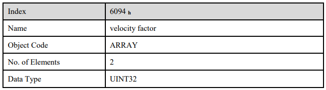
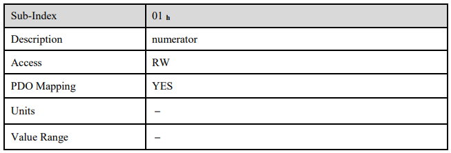

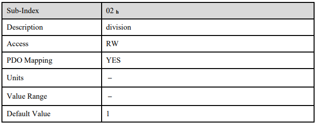
In principle the calculation of the velocity factor is composed of two parts: A conversion factor from internal units of length into position_units and a conversion factor from internal time units into user defined time units (e.g. from seconds to minutes). The first part equals the calculation of the position_factor. For the second part another factor is necessary for the calculation:
time_factor_v
Ratio between internal and user defined time units. (z.B. 1 min = 1/10 10 min)
gear_ratio
Ratio between revolutions on the driving side (RIN) and revolutions on the driven side (ROUT).
feed_constant
Ratio between revolutions on the driven side (ROUT) and equivalent motion in position_units (e.g. 1 R = 360°)
The calculation of the velocity factor is done with the following equation:

6.3.4 Acceleration factor
The object acceleration_factor converts all acceleration values of the application from acceleration_units into the internal unit (0.1rpm) . It consists of numerator and divisor:
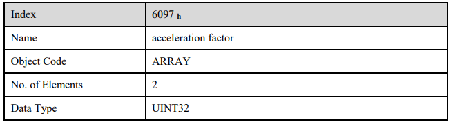
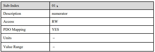

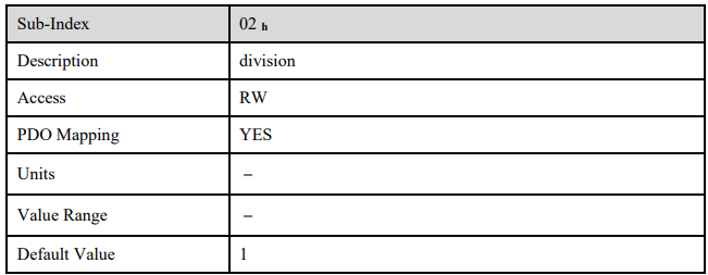
The calculation of the acceleration_factor is also composed of two parts: A conversion factor from internal units of length into position_units and a conversion factor from internal time units squared into user defined time units squared (e.g. from seconds2 to minutes2). The first part equals the calculation of the position_factor. For the second part another factor is necessary for the calculation.
time_factor_a
Ratio between internal time units squared and user defined time units squared (z.B.: 1min2 = 1min*min = 60s*1min =60/10 10min/s)
gear_ratio
Ratio between revolutions on the driving side (RIN) and revolutions on the driven side (ROUT).
feed_constant
Ratio between revolutions on the driven side (ROUT) and equivalent motion in position_units (e.g. 1 R = 360°)
The calculation of the acceleration_factor is done with the following equation:

6.4 Position Control Function
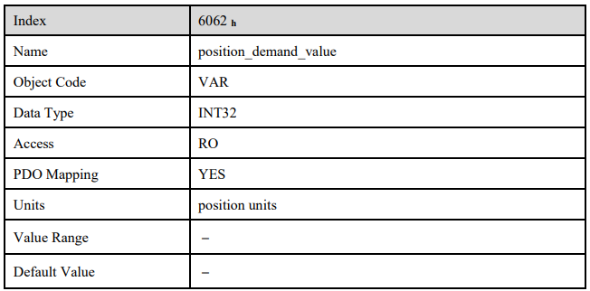
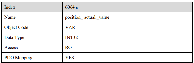
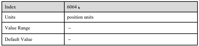
This chapter describes all parameters which are required for the position controller. The desired position value (position_demand_value) of the trajectory generator is the input of the position controller. Besides this the actual position value (position_actual_value) is supplied by the angle encoder (resolver, incremental encoder, etc.). The behaviour of the position controller can be influenced by parameters.
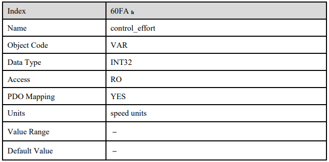
It is possible to limit the output quantity (control_effort) in order to keep the position control system stable. The output quantity is supplied to the speed controller as desired speed value. In the Factor Group all input and output quantities are converted from the application-specific units to the respective internal units of the controller
The following subfunctions are defined in this chapter:
6.4.1 Following error)
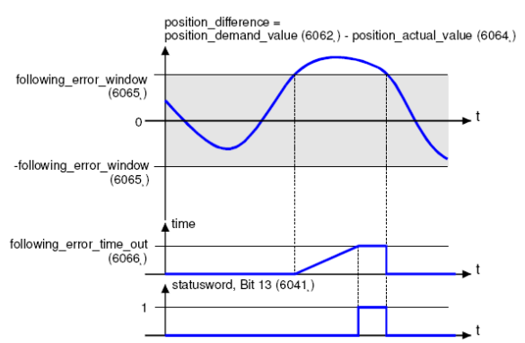
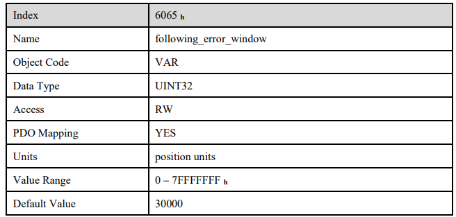
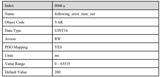
The deviation of the actual position value (position_actual_value) from the desired position value (position_demand_value) is named trailing error. If for a certain period of time this trailing error is bigger than specified in the trailing error window (following_error_window) bit 13 (following_error) of the object statusword will be set to 1.
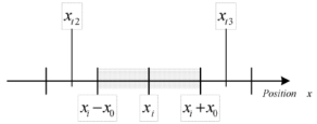
The permissible time can be defined via the object following_error_time_out.. Figure above shows how the window function is defined for the message "following error".The range between xi-x0 and xi+x0 is defined symmetrically around the desired position (position_demand_value) xi. For example the positions xt2 and xt3 are outside this window (following_error_window). If the drive leaves this window and does not return to the window within the time defined in the object following_error_time_out then bit 13 (following_error) in the statusword will be set to 1.
6.4.2 Position Reached
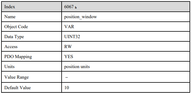
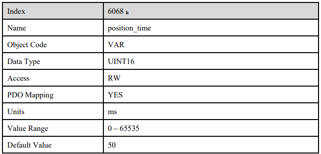
This function offers the chance to define a position window around the target position (target_position). If the actual position of the drive is within this range for a certain period of time – the position_window_time – bit 10 (target_reached) will be set to 1 in the statusword.
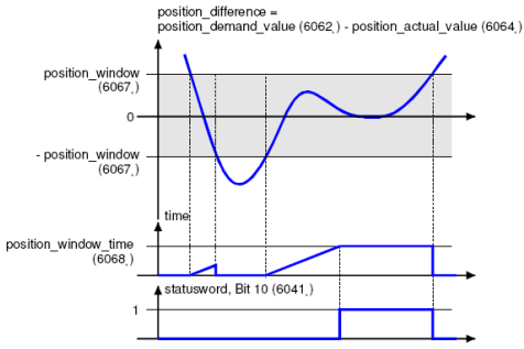
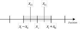
Figure below shows how the window function is defined for the message ”position reached”. The position range between xi-x0 and xi+x0 is defined symmetrically around the target position (target_position) xi. For example the positions xt0 and xt1 are inside this position window (position_window). If the drive is within this window a timer is started. If this timer reaches the time defined in the object position_window_time and the drive uninterruptedly was within the valid range between xi-x0 and xi+x0, bit 10 (target_reached) will be set in the statusword. As far as the drive leaves the permissible range, bit 10 is cleared and the timer is set to zero.
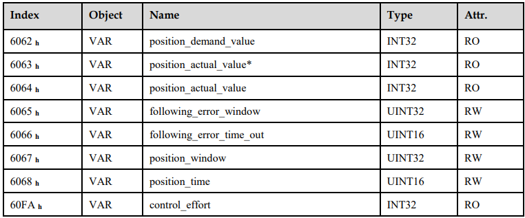
6.4.3 Relevant Parameters
6.5 State machine
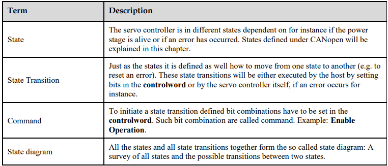
Using CANopen the complete control of the servo is done by two objects. Via the controlword the host is able to control the servo, as the status of the servo can be read out of the statusword. The following items will be used in this chapter:
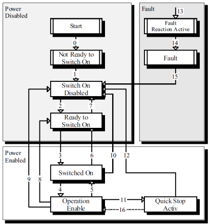
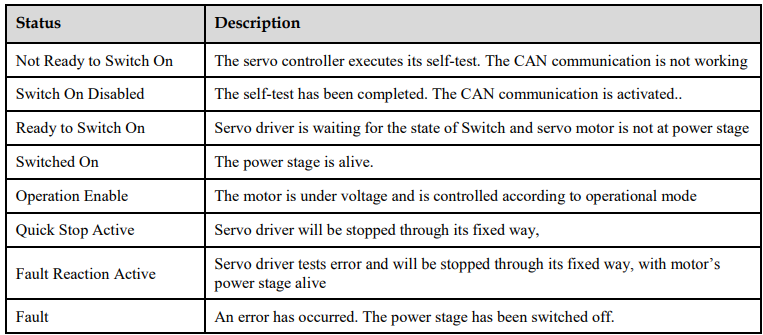
The state diagram can be divided into three main parts: "Power Disabled" means the power stage is switched off and "Power Enabled" the power stage is active. The area "Fault" contains all states necessary to handle errors of the controller. The most important states have been highlighted in the Figure: After switching on the servo controller initializes itself and reaches the state SWITCH_ON_DISABLED after all. In this state CAN communication is possible and the servo controller can be parameterized (e.g. the mode of operation can be set to "velocity control"). The power stage remains switched off and the motor shaft is freely rotatable. Through the state transitions 2, 3 and 4 – principally like the controller enable under CANopen - the state OPERATION_ENABLE will be reached. In this state the power stage is live and the servo controller controls the motor according to the parameterized mode of operation. Therefore previously ensure that the servo controller has been parameterized correctly and the according demand value is zero. The state transition 9 complies with disabling the power stage, i.e. the motor is freely rotatable.
6.6 Relevant Parameters of Device Control

6.6.1 Controlword
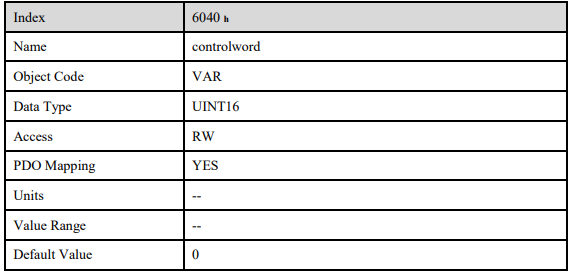
Controlword bit description is as below:

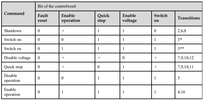
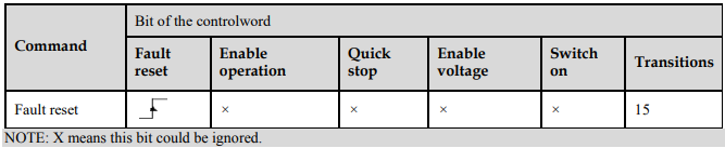
Bit0 ~ 3 and Bit7
Transmit of status machine is triggered by 5 bits coordinated control code as below
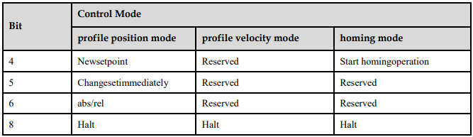
Bit4, 5, 6, 8
The definition of this 4 bit is different in different control mode.
Other bits
All reserved.
6.6.2 Statusword
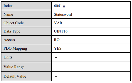
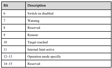
Explanation of statusword bit is as below:
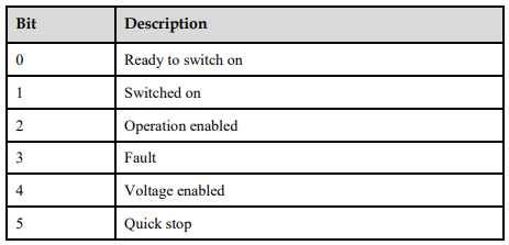
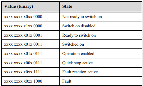
Bit0 ~ 3, Bit5, and Bit6
The combination of this bit indicates the status of drives
Bit4: Voltage enabled
Main power is on when this bit is 1.
Bit5: Quick stop
Driver will follow setting (605A h: quick_stop_option_code) to halt when this bit is 0.
Bit7: Warning
Driver detects alarm when this bit is 1.
Bit9: Warning
Servo can deal with Controlword when this bit is 1 and CANOPEN is enabled.
Bit10: Target reached
In different control modes the meaning of this bit is different.
In profile position mode, when set position is reached, this bit is set. When Halt is booted, speed is reduced to 0 and this bit will be set. When new position is set, this bit will be cleared.
In profile Velocity Mode, when the speed reaches the targeted speed, this bit will be set. When Halt is booted and speed is reduced to 0, this bit is set.
Bit11: Internal limit active
When this bit is 1, it indicates that internal torque has surpassed the set value,or reached the max.forward/reverse run.It can be confirmed by reading object 60FDh (digital inputs) .
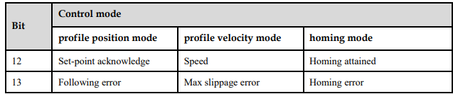
Bit12, 13
These 2 bits mean different in different control mode.
Other bits
All reserved.
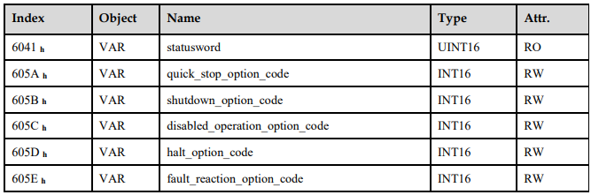
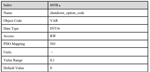
6.6.3 Shutdown_option_code
The object shutdown_option_code determines the behaviour if the state transition 8 (from OPERATION ENABLE to READY TO SWITCH ON) will be executed.

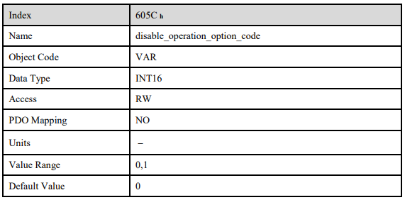
6.6.4 Disable_operation_option_code
The object disable_operation_option_code determines the behaviour if the state transition 5 (from OPERATION ENABLE to SWITCHED ON) will be executed.

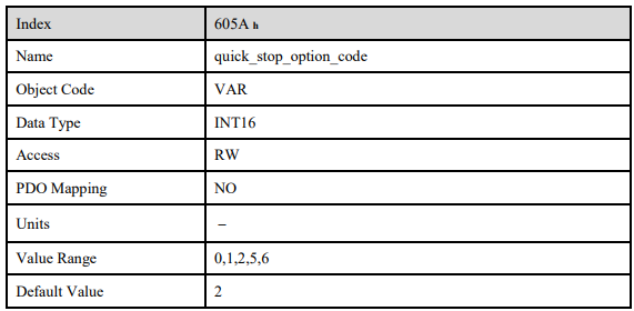
6.6.5 Quick_stop_option_code
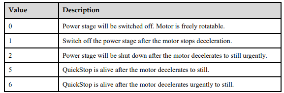
The object quick_stop_option_code determines the behaviour if a Quick Stop will be executed.
6.6.6 Halt_option_code
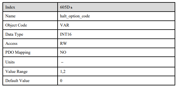
Halt_option_code determines how to stop when bit.8 (halt) of controlword is set to 1.

6.6.7 Fault_reaction_option_code
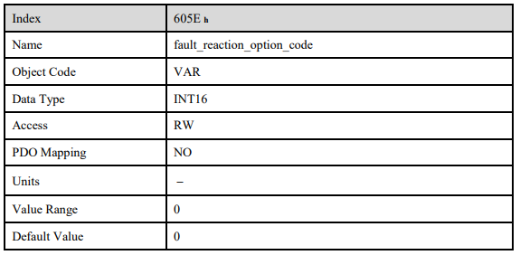
When an error is occurred, fault_reation_option_code determines how to stop.

No comments to display
No comments to display