
4. Panel Operator
4.1 Basic Operation
4.1.1 Functions on Panel Operator
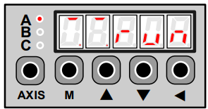
The panel operator is a built-in operator that consists of display section and keys located on the front
panel of the servo drive.
Parameter setting, status display ,and execution of utility function are enabled using the panel operator.
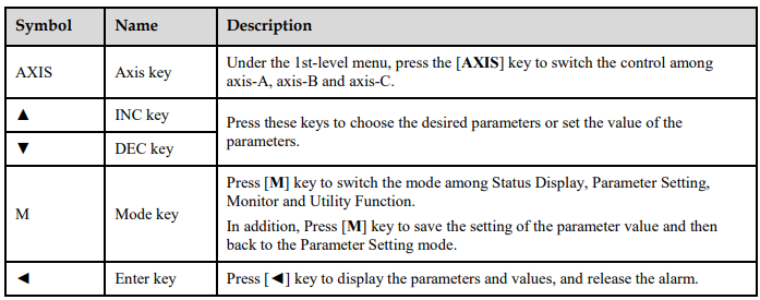
The names and functions of the keys on the panel operator are shown as follows:
4.1.2 Axis Switching
Since the Servodrive only can set and monitor only one axis at a time, the use can press the [AXIS] key to switch the control into another axis. The indicator lamp behind each axis can show the work status:
Lit indicates the axis is controlled at present.
Not lit indicates the axis is not controlled at present.
Blinking indicates an alarm occurred in the axis not controlled at present.
4.1.3 Mode Switching
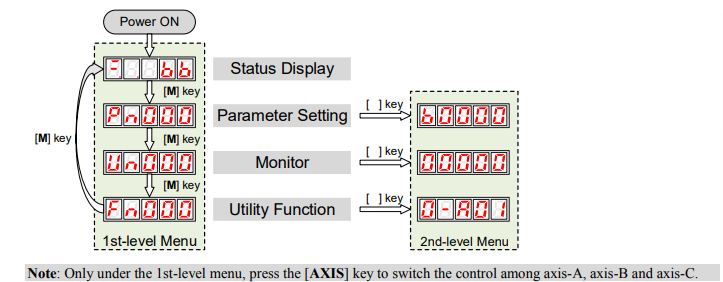
As is shown in the following figure, press [M] key can switch the mode among Status Display, Parameter Setting, Monitor and Utility Function in turns.
4.2 Status Display
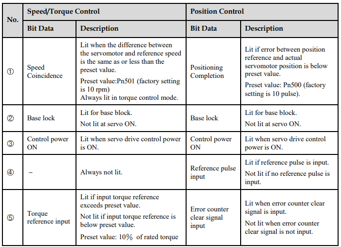
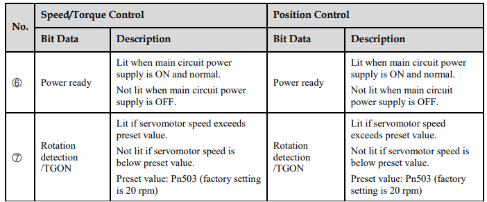
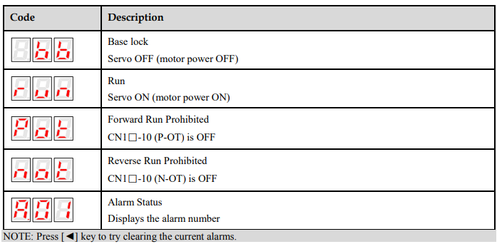
The status display mode displays the servo drive status as bit data and codes.
The status display mode is selected when the power supply is turned ON. If it is not displayed, select this mode by pressing [M] key.
Note that the display differs between the speed/torque control and position control.
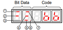
The following table lists the description of each bit data in speed/torque control and position control.
The following table lists the description of code.
4.3 Operation in Parameter Setting Mode
The servo drive offers a large number of functions, which can be selected or adjusted by the parameter settings. For details about each parameters description see the section Appendix A Parameters List.
The following procedure is an example for changing the setting of parameter Pn102 from 100 to 85.
Step 1 Press [M] key for several times to switch into Parameter Setting mode, after turning the Servodrive ON.
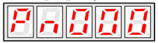
Step 2 Press [▲] key or [▼] key to select the parameter Pn102.
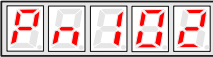
Note: press and hold [▲] key or [▼] key to jump the parameter number quickly.
Step 3 Press [◄] key to display the current value of Pn102.
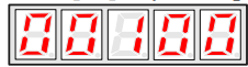
Step 4 Press [▼] key or [▼] key to change the value to 00085. Press and hold [▼] key or [▼] key to jump the setting value quickly.
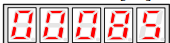
Step 5 Press [◄] key or [M] key to return to the display of the current parameter.
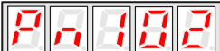
----End
4.4 Operation in Monitor Mode
The monitor mode allows the reference values input into the servo drive, I/O signal status, and servo drive internal status to be monitored.
Using the Monitor Mode
The example below shows how to display the value (1500) stored in Un001.
Step 1 Press [M] key for several times to switch into Parameter Setting mode, after turning the Servodrive ON.
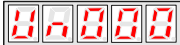
Step 2 Press [▲] key or [▼] key to select the monitor number Un001.
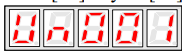
Step 3 Press [◄] key to display the current value of Un001.
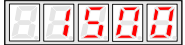
Step 4 Press [◄] key again to return to the display of the current monitor number.
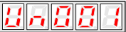
----End
Descriptions of Monitor Number
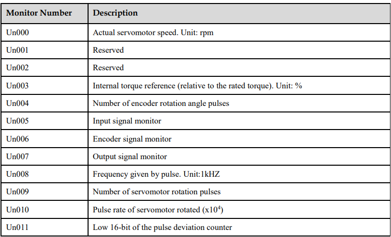
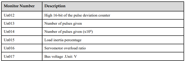
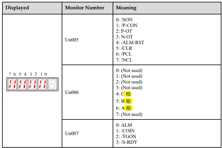
In which, the display meaning of Un005, Un006 and Un007 are shown as following table.
4.5 Operation in Utility Function Mode
In utility function mode, the panel operator can be used to run and adjust the servo drive and servomotor.
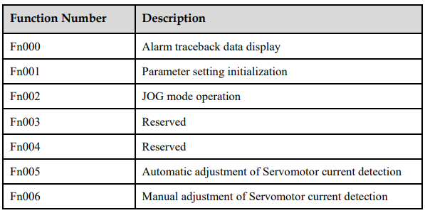
The following table lists the functions in the utility function mode.
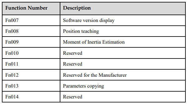
4.5.1 Alarm Traceback Data Display
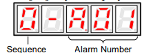
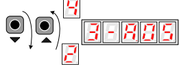
The alarm traceback display can display up to 10 previously occurred alarms.The alarm is displayed on Fn000, which is stored in the alarm traceback data.
Follow the procedures below to confirm alarms which have been generated.
Step 1 Press [M] key for several times to switch into Utility Function mode, after turning the Servodrive ON.
Step 2 Press [▲] key or [▼] key to select the function number Fn000.
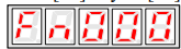
Step 3 Press [◄] key to display the latest alarm number.
Step 4 Press [▲] key or [▼] key to display another alarm numbers occurred recently.
Step 5 Press [◄] key to return to the display of the current function number.
----End
4.5.2 Parameter Settings Initialization
Follow the procedures below to perform the parameter settings initialization.
Step 1 Press [M] key for several times to switch into Utility Function mode, after turning the Servodrive ON.
Step 2 Press [▲] key or [▼] key to select the function number Fn001.
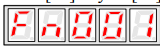
Step 3 Press [◄] key to prepare for initializing the parameter settings.
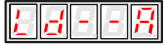
Initialize the parameter settings of axis-A
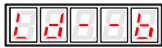
Initialize the parameter settings of axis-B
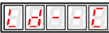
Initialize the parameter settings of axis-C
Step 4 Press and hold [◄] key for 1 second or more until “done” is displayed and blinked, which indicates the parameter settings initialization has been completed.
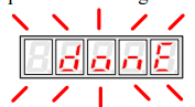
Step 5 Relase [◄] key to return to the display of the current function number

----End
4.5.3 JOG Operation
Follow the procedures below to operate the Servomotor in JOG.
Step 1 Press [M] key for several times to switch into Utility Function mode, after turning the servo ON.
Step 2 Press [▲] key or [▼] key to select the function number Fn002.
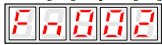
Step 3 Press [◄] key to enter the JOG running mode.
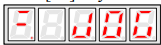
Step 4 Press [M] key to turn ON the servo.
Here, you can press [M] key to turn ON or turn OFF the servo. However, Turn ON the servo if you want to run the Servomotor.
Step 5 Press [▲] key or [▼] key to run the Servomotor forward or reverse in a certain amount of movement. Press and hold [▲] key or [▼] key to run the Servomotor continuously.

NOTE: the rotation direction of the Servomotor depends on the setting of Pn001.0. The above figure shows the
default setting.
Step 6 Relase [◄] key to return to the display of the current function number.
Moreover, the servo is turned OFF automatically.
----End
4.5.4 Offset Adjustment for Current Detection
Since the Offset Adjustment for Current Detection has been performed before the device leaves the factory, the user does not need to perform this operation generally.
However, Offset Adjustment for Current Detection shall be peformmed when the torque ripple was too large or if you want to further reduce the torque ripple.
This section describes the automatic and manual offset adjustment for current detection.

Automatic Adjustment
Following the below procedure to perform the automatic adjustment.
Step 1 Press [M] key for several times to switch into Utility Function mode, after turning the servo ON.
Step 2 Press [▲] key or [▼] key to select the function number Fn005.
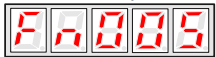
Step 3 Press [◄] key to prepare for performing the automatic adjustment.
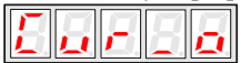
Step 4 Press and hold [M] key for 1 second or more until “done” is displayed and blinked, which indicates the automatic adjustment has been completed.
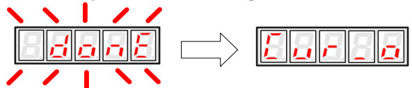
Step 5 Press [◄] key to return to the display of the current function number.
----End
Manual Adjustment
Following the below procedure to perform the manual adjustment.
Step 1 Press [M] key for several times to switch into Utility Function mode, after turning the servo ON.
Step 2 Press [▲] key or [▼] key to select the function number Fn006.
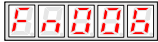
Step 3 Press [◄] key to prepare for performing the manual adjustment.
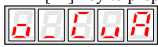
Step 4 Press [M] key to select the desired setting phase between phase-U (o_CuA) and phase-V (1_Cub).

Step 5 Press and hold [◄] key for 1 second, the detection value of current phase is displayed

Step 6 Press [▲] key or [▼] key to change the value for the adjustment.

Step 7 Press and hold [◄] key for 1 second to return to the setting phase.
Step 8 Press [◄] key to return to the display of the current function number.

----End
4.5.6 Position Teaching Function
Following the below procedure to perform the postion teaching.
Step 1 Press [M] key for several times to switch into Utility Function mode, after turning the servo ON.
Step 2 Press [▲] key or [▼] key to select the function number Fn008.
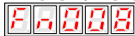
Step 3 Press [◄] key to prepare for the position teaching.
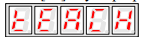
Step 4 Press and hold [◄] key for 1 second or more until “done” is displayed and blinked, which indicates the position teaching has been completed.
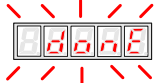
Step 5 Relase [◄] key to return to the display of the current function number.
----End
4.5.7 Moment of Inertia Estimation
Following the below procedure to perform the Moment of Inertia Estimation.
Step 1 Press [M] key for several times to switch into Utility Function mode, after turning the servo ON.
Step 2 Press [▲] key or [▼] key to select the function number Fn009.
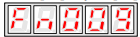
Step 3 Press [◄] key to prepare for the Moment of Inertia Estimation.
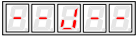
Step 4 Press [M] key for performing the operation.
The real-time rotational speed of the Servomotor is displayed.
Step 5 When the Servomotor is stopped, the estimation value is displayed on the panel operator, and its unit is kg.cm2
.

----End
4.5.8 Parameters Copying
Following the below procedure to perform the Parameters Copying.
Step 1 Press [M] key for several times to switch into Utility Function mode, after turning the servo ON.
Step 2 Press [▲] key or [▼] key to select the function number Fn013.
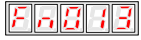
Step 3 Press [◄] key to prepare for the parameters copying.
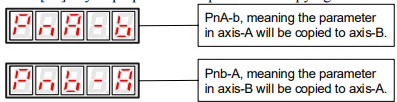
The meaning of the other displays are similar to the above.
Step 4 Press and hold [◄] key for 1 second or more until “done” is displayed and blinked, which indicates the parameter copying has been completed.
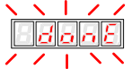
Step 5 Relase [◄] key to return to the display of the current function number.
----End
No comments to display
No comments to display