
6. ZERO CALIBRATION
6.1.OVERVIEW
Zero calibration refers to the operation of correlating the angle of each robot joint with the pulse count value. The purpose of the calibration is to obtain the pulse count value corresponding to the zero position.
"Zero Calibration" is done before leaving the factory. It is not necessary to calibrate in daily operation.
However, a calibration operation is required in the following cases.
Motor replacement
Pulse coder replacement
Reducer replacement
Cable replacement
The battery used for pulse count backup in the machine body is exhausted

6.2.DEDICATED INSTRUMENT CALIBRATION
The factory setting requires removing all loads and completed with a dedicated instrument. This calibration method is based on the parameters of the whole robot, using professional instruments and software, and the zero point is the most accurate.
If the zero position data is lost due to electrical or software problems, the saved zero position data is restored as a quick teaching and debugging reference. This method cannot be used if the robot zero point data is lost due to mechanical disassembly or repair.
The company uses the robot encoder information to assist the zero position calibration. The steps are as follows:
a) Manually operate the robot to adjust the axis to the alignment of the zero mark and tick marks.
b) Open the encoder information display interface, compare the deviation between the current actual single-turn data and the last calibration given single-turn data, and adjust the axis at a lower speed so that the current single-turn data is basically equal to the given single-turn data.
c) Calibrate the axis zero point. Create a new program in the teach pendant, create a new command "RefRobotAxis", select the axis number to be calibrated, and execute the command.
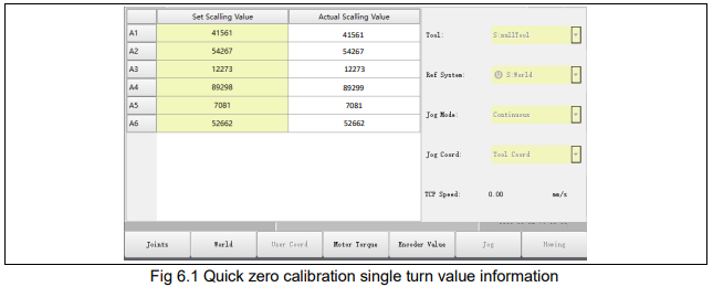
6.3.MECHANICAL ZERO CALIBRATION
Mechanical disassembly or maintenance may cause zero position data lost. Mechanical zero position calibration is performed with all axes jogged to zero-position using their respective witness marks.
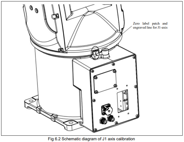
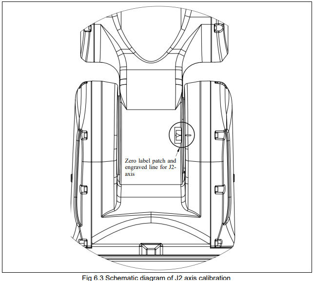
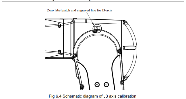
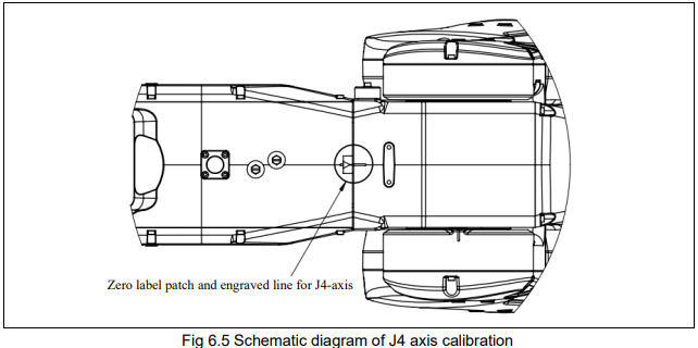
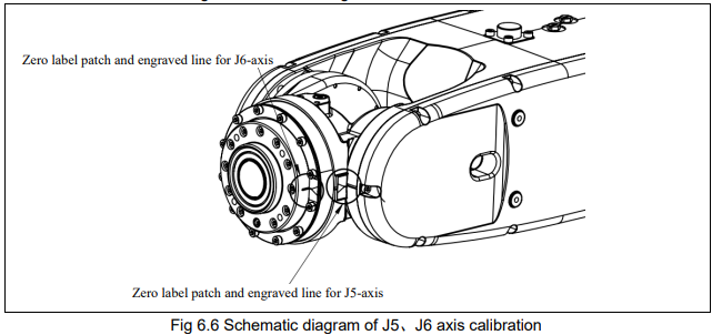
The zero calibration of the equipment is mainly to calibrate the joint score line and the middle score line of the zero mark patch by visual inspection. Now take J1 axis as an example to calibrate the zero point of this joint: adjust the robot to align the scale line indicated in the figure.
As shown in the figure, there is a mark on the base and the swivel. Please comply with the following steps to calibrate.
a) Use the teaching box to rotate the J1 axis so that the middle scale lines of the two scale plates are aligned.
b) Set this position as the zero point position of J1 axis through the teaching box.
At this point, the calibration of J1 axis has been completed. The user can refer to the above steps to complete the calibration of other axes, or after finding the zero point positions of all joints, set the zero point positions of all joints at once through the teaching box. The other schematics in this section will help the user with the calibration operation.
6.3.1.MECHANICAL ZERO CALIBRATION
No comments to display
No comments to display