
4. Equipment Installation
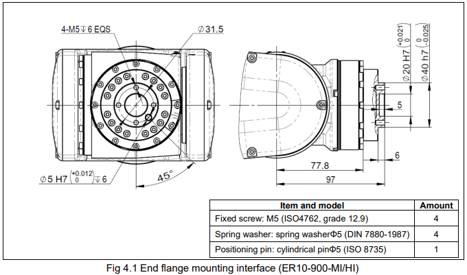
4.1. End flange mounting interface
This section describes the mounting face dimension of the end flange. Consider the depth of the screw holes and pin holes sufficiently before choose the length of the bolts and pins. Antirust measures of screws, grippers, etc., should be considered as well.
4.2. Equipment mounting face
The figure indicates the locations of the screw holes for equipment installation. The robot has external device mounting threaded holes located on the top of the small arm component.
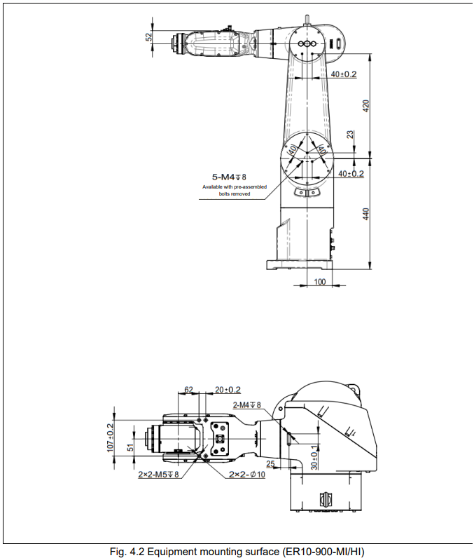

When installing the robot body, it is important to strictly adhere to the following precautions to avoid deformation of the rotating base.
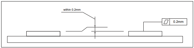
(1) The flatness of the robot mounting panels (4 in total) should be within 0.2mm.
(2) The relative height error of the installation surfaces of the robot mounting panels (4 in total) should be within 0.2mm (±0.01mm).
4.3. External pipelines
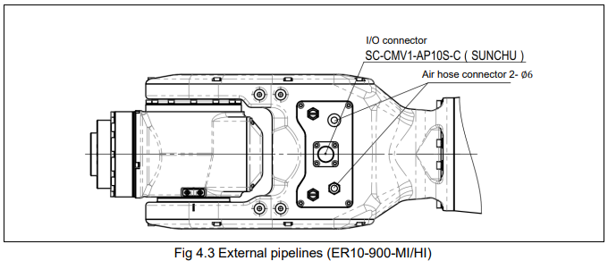
This mini series of robots provides pathways for supplying pneumatic or hydraulic pressure to the end effector mechanism.
4.3.1. Description of robot IO connector pins
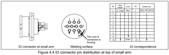
The robot provides 10-pin IO connectors on the top of the small arm and on the control cabinet, respectively. These two connectors are connected through specific internal cables within the robot body, as shown in the diagram below.
No comments to display
No comments to display