
5. Check and Maintenance
Before performing any maintenance, be sure to read SAFETY PRECAUTIONS in Chapter 1 and understand the content.
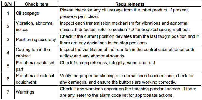
5.1. Daily checks
Check the items below before daily operation as occasion demands.
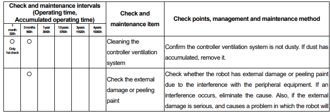
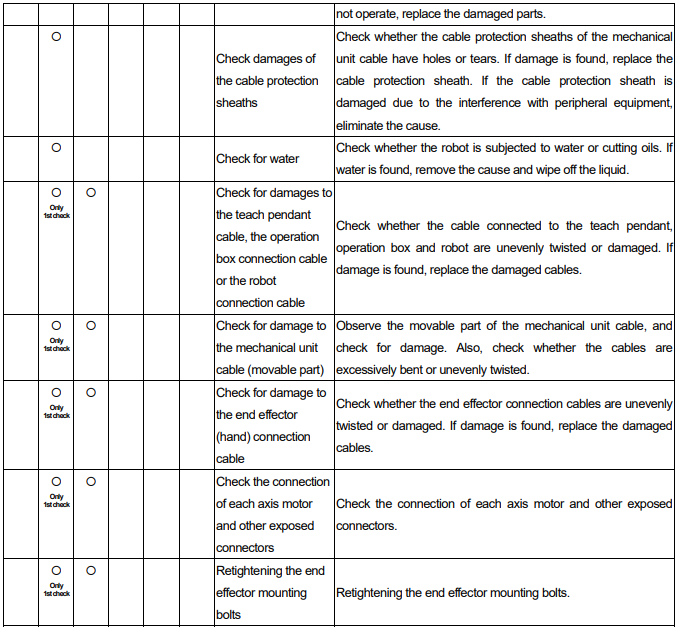
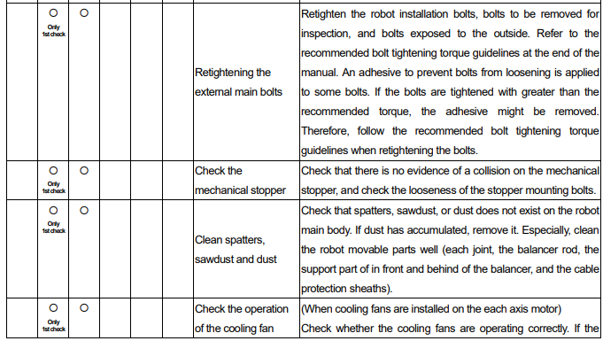
5.2. Periodic checks and maintenance
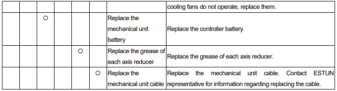
Perform maintenance and repairs at approximate intervals based on the specified operating cycle or cumulative operating time. By following the regular maintenance steps, the robot's optimal performance can be maintained. Users can carry out scheduled inspections and maintenance according to the table below, or they can contact ESTUN's professionals for service.
5.3. Adjustment of drive belts
After a period of use, the tension of the timing belt may decrease, and it will require re-tensioning.
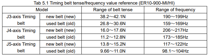
When measuring the tension of the timing belt, it is recommended to prioritize measuring the frequency (Hz) for assessment. When using the frequency mode for measurement, there is no need to adjust the internal parameters of the tensioning device.

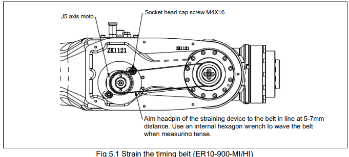
In the ER10-900-MI/HI robot, the J3, J4, and J5 axes are driven by timing belts. Here are the steps to tension the timing belt for the J5-axis (similar steps can be followed for other axes):
1. Remove the hexagon socket head cap screws M3×8 from the cover plates of the forearm, and place the cover plates in the designated storage area;
2. Loosen the fixing screw M4X16 on the J5 axis motor;
3. Adjust the adjustment device next to the J5 axis motor, primarily adjusting the M4 bolt to apply tension to the J5 axis motor;
4. Test the tension of the timing belt on the side of the belt and adjust it to an appropriate tension (refer to the specific range in the table below);
5. Tighten the socket head cap screw M4X16 to fix the J5 axis motor securely;
6. Place the small arm cover plate in its installation position and tighten it using the hexagon socket cap screw M3X8
5.4. Replacement of batteries
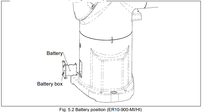
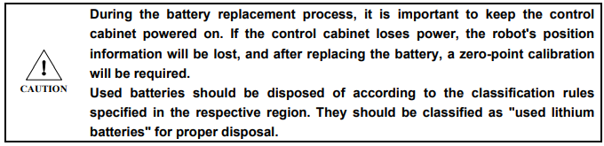
The position data of each axis is preserved by the backup batteries. The batteries need to be replaced every 1 year. Also use the following procedure to replace when the backup battery voltage drop alarm occurs.
Procedure of replacing the battery is shown below:
1.Press the emergency stop button to stop the robot motion.
2. Remove the plug cover on the robot base.
3. Take out the old batteries from the battery case.
4. Insert new batteries into the battery case while observing the correct direction.
5. Re-mount the cover after replacing the battery.
5.5. Robot greasing
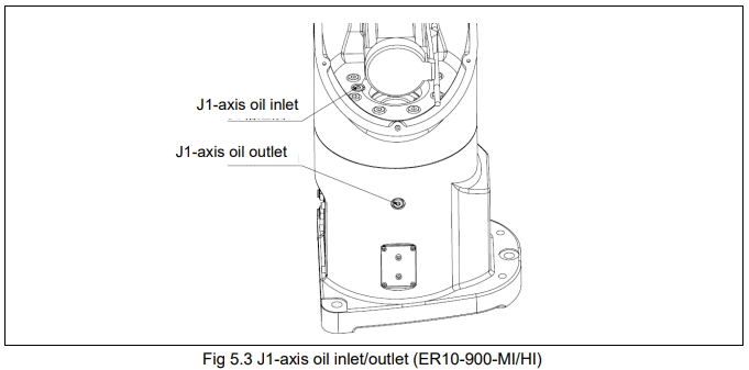
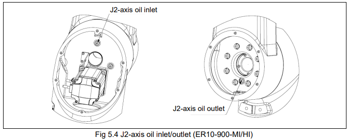
The lubrication of the J1 and J2 axes of the ER10-900-MI/HI robots should be replaced on a cycle that is determined by the shorter duration between every 3 years or accumulated operating time reaching 11,520 hours. The lubricant types and grease quantities for each joint are provided in the table below.


The replenishment of lubricant for the J1 and J2 axes can be done at any joint angle.
For the J3 to J6 axes, under normal operating conditions, lubricant replenishment is not required (except when replacing the reducer). However, under harsh conditions such as high duty cycle, high-speed movements, or heavy load, regular lubricant replenishment is necessary. For any inquiries regarding lubricant replenishment, please contact ESTUN.
5.5.1. Steps to replace grease
The following procedure is specific to the J1 and J2 reducers of ER10-900-MI/HI robots. Please follow the steps below:
a) Teach each joint of the robot at 100% speed for 10-20 minutes to convert the internal grease into a lower viscosity oil;
b) Move the robot to the lubrication joint angle and disconnect the power supply;
c) Place a grease collection container below the oil drain port;
d) Remove the plugs from the corresponding oil drain and grease injection ports;
e) Inject new grease into the grease injection port until the grease discharged from the oil drain port matches the newly added grease. Adjust the injection volume using a measuring tool to ensure the amount of grease added is consistent with the amount discharged (including that discharged after warm-up).
f) Release residual pressure from the grease chamber following the steps outlined in 5.5.3;
g) Install and tighten the plugs on the grease injection and oil drain ports with a torque of 13.7N·m.
If lubrication is not performed correctly, the internal pressure of the lubrication chamber may suddenly increase, potentially damaging sealing parts and leading to grease leakage and abnormal operation. Therefore, please adhere to the following precautions during the lubrication operation:
Before performing the grease injection, open the lubricant vent (remove the plug from the lubricant outlet).
Slowly inject the lubricating oil/grease and avoid applying excessive force.
Whenever possible, avoid using compressed air pumps (driven by the factory air source).
Only use lubricating oil/grease of the specified type. The use of lubricants other than the specified type may damage the gearbox or cause other issues.
Upon lubrication, ensure there is no leakage of lubricating oil/grease from the outlet and that the lubrication chamber is not pressurized before closing the lubricant outlet.
To prevent accidents such as slipping or fire, thoroughly remove excess lubricating oil/grease from the ground and the robot.
5.5.2.Steps to release residual pressure in the grease chamber
Please follow the steps below to release residual pressure. During this process, install a collection bag below the oil drain port to prevent scattered grease.
a) Start the robot and load the robot running-in program to continuously operate the robot under full load and 100% speed for 4 hours;
b) Stop the robot running program and bring the robot to the home position. Disable the robot from the teach pendant.
c) After ensuring safety, remove the plugs from the grease injection ports of each axis. When removing the plugs, do not directly face them to prevent high-pressure, high-temperature oil spray that could cause injury to personnel.
d) After dismantling the plugs, wait for 3 to 5 seconds, then tighten them again. Clean the area around the plugs with a clean cloth to remove any oil.
e) It is essential to complete the pressure release process (steps c and d) for one product within 15 minutes. Otherwise, the procedure should be restarted from step a.
5.6. Oil leakage inspection
Maintenance Area
Insert a cloth or similar material into the gaps of each joint to check for any oil leakage from the oil seals. If oil leakage is observed, please wipe it clean.
⚫ Depending on the operating conditions and surrounding environment, oil may leak from the outer lip of the oil seals. When accumulated oil forms droplets, it may drip during certain movements. Prior to operating the robot, please wipe off any oil accumulation on the underside of the oil seals.
⚫ Additionally, if the temperature during operation is excessively high, the internal pressure in the joint chambers may increase. In such cases, after the operation, please open the oil filling port once to restore the internal pressure. (Do not open or close the oil filling port while the machine is in a cooled state)
⚫ If oil leakage persists even after frequent wiping, please refer to 7.2 Troubleshooting.

No comments to display
No comments to display