
2. Product Confirmation
2.1 Product confirmation
2.1.1 Contents confirmation
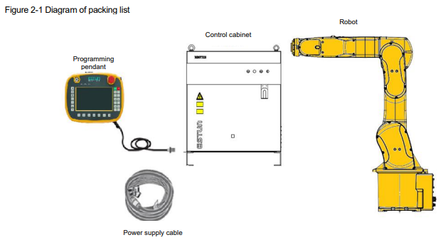
Confirm the contents of the delivery when the product arrives. Standard delivery includes the following four items: (information for the content of optional goods is given separately).
Robot
Control cabinet
Programming pendant
Interconnection cable (between robot and control cabinet)
2.1.2 Order number confirmation
Confirm whether the order number pasted on the robot and control cabinet match.
2.2 Control cabinet
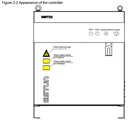
This section takes the standard control cabinet as an example and gives a brief introduction to the appearance of the control cabinet and the buttons. The appearance of the buttons and internal structure of the control cabinet varies from model to model. For detailed descriptions, please refer to the instruction manual supplied with the model of control cabinet.
The appearance of the control cabinet and the distribution of buttons on the exterior of the electrical cabinet are shown in Figure 2-2.
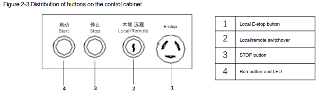
The distribution and illustrations of the control cabinet panel keys are shown in Figure 2-3.
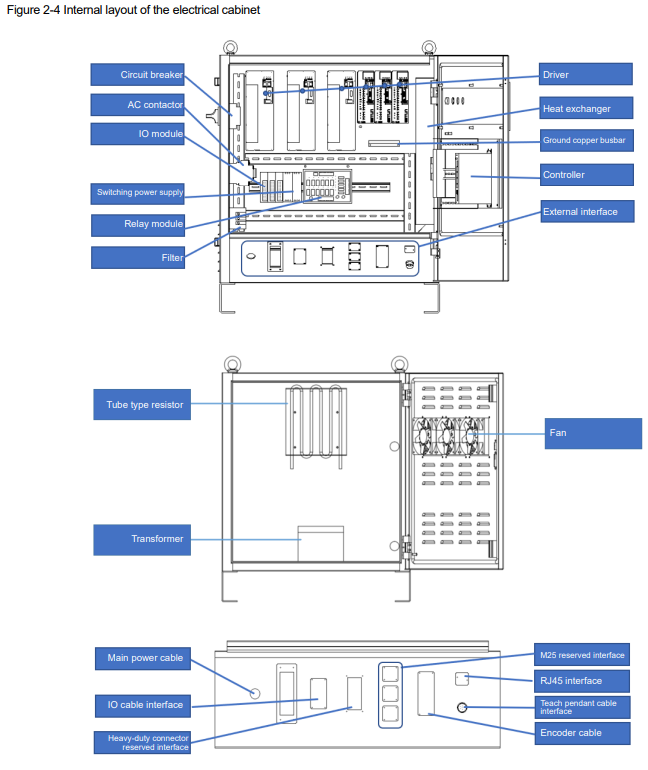
The internal layout of the electrical cabinet is shown (the layout of the control cabinet varies between robots):
2.3 Programming pendant
2.3.1 Appearance
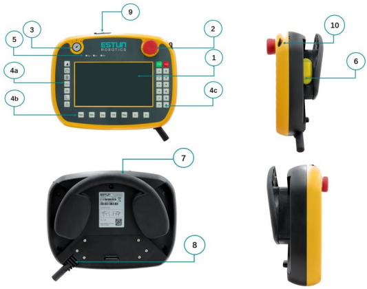
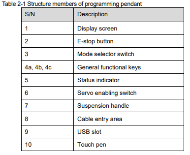
The programming pendant consists principally of the keys and buttons required to teach and program the robot.
Figure 2-5 Appearance of programming pendant
2.3.2 Touch pen
The touch pen is supplied with the teach pendant and is placed on the back of the teach pendant and can be pulled out when in used. No screwdrivers or other sharp objects should be used when clicking on the display of the teach pendant with the touch pen.
2.3.3 USB slot
Connect a USB memory to the USB port to read or save files.
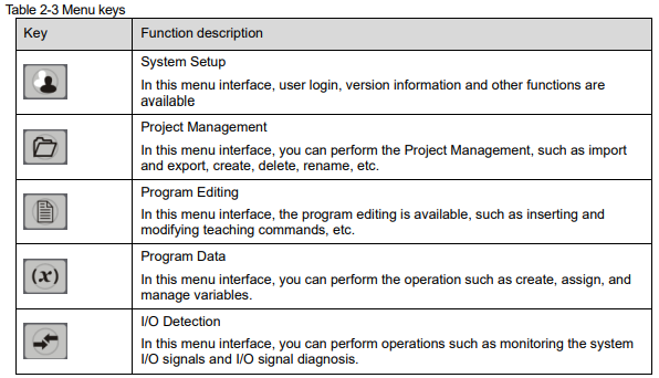
2.3.4 Keys
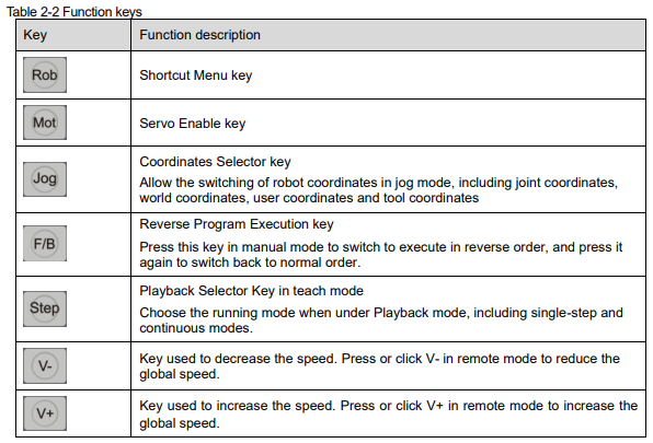
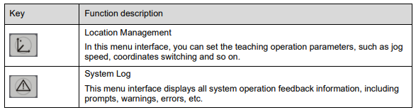
Function keys
Function keys are arranged under the programming pendant. Table 2-2 lists the functions of each key.
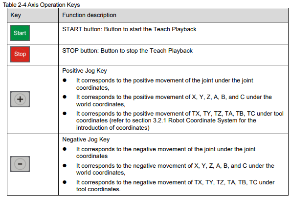
Axis Operation Keys
Axis Operation Keys are arranged on the right side of the programming pendant. Table 2-4 lists the functions of each key.
2.3.5 Display
Display Area
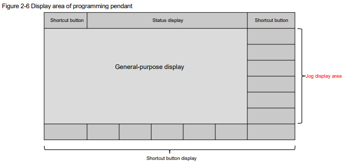
The display screen of the programming pendant is a 7-inch color display, on which the figures, letters and symbols are displayed. The display screen is divided into 4 areas, the general display area, status display area, shortcut button display area and jog display area. The display area interface of the programming pendant is shown in Figure 2-6.
General-Purpose Display Area
On the general-purpose display area, various settings and contents such as jobs, characteristics files and settings can be displayed and edited.
Status Display Area
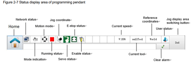
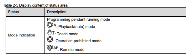
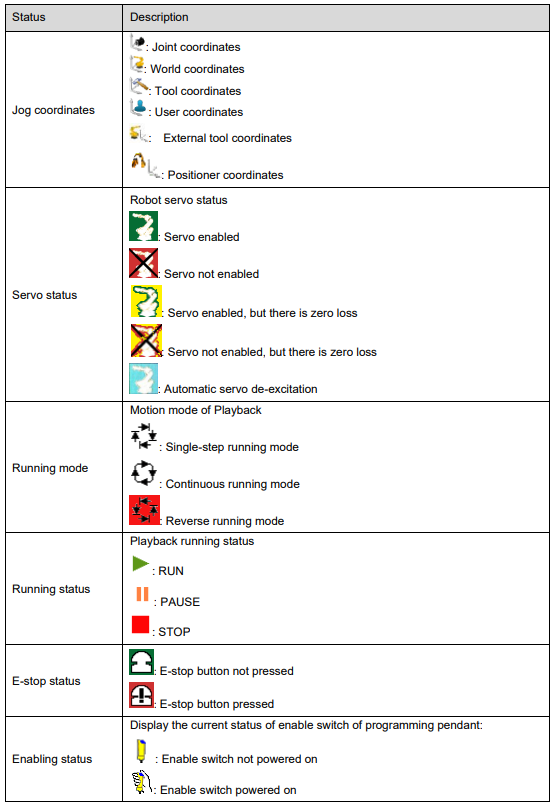
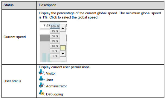
The Status Display area shows system status, including operation mode, servo status, jog coordinates and jog speed, etc., as shown in Figure 2-7.
2.3.6 Mode switches
Toggle the keys to switch between the three modes. Three modes are available for system running:
1. Turn the key above the actual teach pendant to switch the robot from AUTO mode to MANUAL mode and the speed is automatically adjusted to 10%.
2. In remote mode, press or click on the teach pendant V+ to increase the global speed and press or click on V- to decrease the global speed.
3. The minimum global speed of 1% is supported.
Manual Mode (Teaching Mode)
You can do followings under teach mode:
Edit and teach the programs
Revise the program that have already been logged in
Set program files and parameters.
Auto Mode (Playback mode)
You can perform following operation under Playback mode:
Playback of teaching program
Setting, modification or deletion of program files.
Remote Mode
System may call out the programs stored in the memory at any time for editing and execution.
The program to be edited is called "Editor Program", which is the program displayed when the program
content is displayed in the teaching mode.
The program to be executed is called "Executive Program", which is the program displayed when the
program content is displayed in Playback mode.
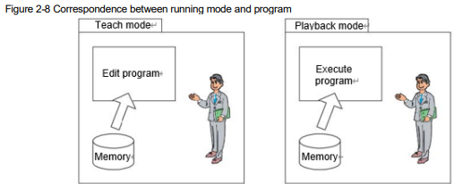
When switching the motion mode on the programming pendant, there will be no conversion between the editing program and the executive program. To run an editing program in Playback mode, you need to change the mode to Playback mode, and then read the program.
2.3.8 Servo enable switch
In teach and jog modes, to enable the servo (excitation), you need to press the servo enable switch. It serves to control the turn-on and turn-off of the enable signal.
Switch Position: On the right-hand handle of the teach pendant
Enabling signal ON: first contact point at which the switch is pressed.
Enabling signal OFF: switch pressed to the bottom or switch button released.
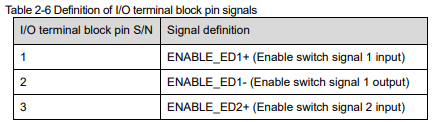
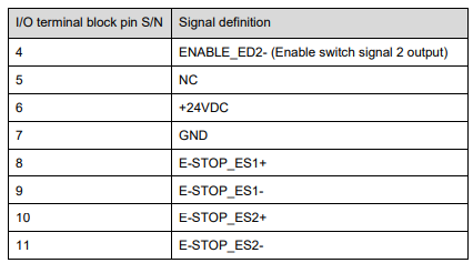
2.3.9 Signal definition of internal wiring terminal of programming pendant
2.3.10 Programming pendant cables
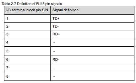
Signal definition of aviation plug interface
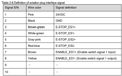
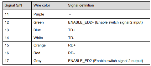
Connection between cable and control cabinet
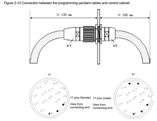
The signal definition of each pin of K1 and K2 is the same as that listed in the signal definition of the aviation plug interface.
No comments to display
No comments to display