
6. Introduction to Commands
6.1 Motion commands
The list of motion commands is shown in Figure 6-1.
Figure 6-1 List of motion commands
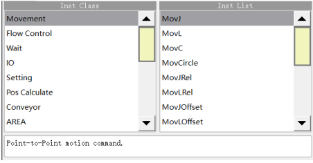
MovJ - Point-to-point motion command
It indicates that each joint of the robot performs point-to-point motion. The end trajectory of the robot is an irregular curve, and the IO command can be operated when the command operates to an end, as shown in Figure 6-2.
Figure 6-2 Parameter editing interface of MovJ
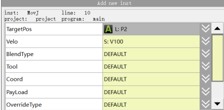
Target position: The final position of the command.
− When set to "APOS", the coordinates of each axis in joint space.
− When set to "CPOS", the position of the TCP point in the Cartesian coordinates. The target position depends on the configuration of confdata. If the mode parameter is set to -1, the end position is not limited by the value of confdata, but the optimal solution to the destination.
Target speed: The running speed of command.
− When setting it to “DEFAULT”, the default value V4000 will be used.
− When it is set to SPEED variable, you can select the system pre-defined one, or create it by yourself; the item per controls the MovJ command, which is the percentage of the global speed.
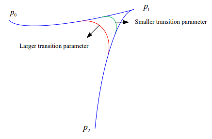
Transition type: The way of transition when the robot approaches the endpoint.
− DEFAULT: Default, i.e. no transition parameter is set in the command. If the SetBlendParam parameter is used in the program, the transition mode operates as per the globally set transition parameter.
− FINE: Equivalent in effect to DEFAULT.
− RELATIVE: Relative transition. The transition parameter is a relative value that represents the percentage of the distance from the transition point to the path endpoint relative to the full length of the path.
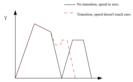
− ABSOLUTE: Absolute transition. The transition parameter is an absolute value that represents the distance from the transition point to the endpoint of path.
MovL - Linear motion command
MovL is the linear motion command, through which the TCP point of the robot can be moved linearly to the target position at the set speed. If the start and end postures of the motion differ, then during operation the posture will synchronously rotate to the ending posture along with the position. It is the same as MovJ. An additional IO operation can be performed when the command is executed. The parameter setting of MovL is similar to MovJ, but its target speed is an absolute speed value, rather than the percentage.
Figure 6-3 Parameter editing interface of MovL
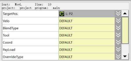
Target Position: The commanded ending position, which can be of type APOS or CPOS. Select an existing point in the drop-down list or create and teach a new variable in the pop-up dialog.
Target speed: The running speed of command.
− When setting it to “DEFAULT”, the default value V4000 will be used.
− When it is set to SPEED variable, you can select the system pre-defined one, or create it by yourself; the item per controls the MovJ command, which is the percentage of the global speed.
Transition type: The way of transition when the robot approaches the endpoint.
− DEFAULT: Default, i.e. no transition parameter is set in the command. If the SetBlendParam parameter is used in the program, the transition operates according to the globally set transition parameter.
− FINE: Equivalent in effect to DEFAULT.
− RELATIVE: Relative transition, where the transition parameter is a relative value that represents the distance from the transition point to the end of the track as a percentage of the full trajectory path.
− ABSOLUTE: Absolute transition, where the transition parameter is an absolute value indicating the distance from the transition point to the endpoint of path.
Transition Value: The transition value when the robot approaches the endpoint.
− When setting it to “DEFAULT”, the default value C100 will be used.
− When it is set to ZONE variable, you can select the system pre-defined one, or create it by yourself; it means no transition when the variable value is 0; the greater the transition value, the larger the transition radius.
Tool Parameters: The tool parameters used when the robot executes the path.
− When setting it to “DEFAULT”, the tool parameters set last time will be continuously used.
− When it is set to TOOL variable, you can select the system pre-defined one, or create it by yourself.
When using a coordinate system different from the current tool parameters, the system will switch the tool parameters to the set ones. If the tool parameters of the path of current segment and the preceding/next segments change, the transition will not be supported.
Coordinate System Parameters: The coordinate system parameters used by the robot when executing the path.
− When setting it to “DEFAULT”, the tool coordinate system set last time will be continuously used.
− When it is set to USERCOOR variable, you can select the system pre-defined one, or create it by yourself. When a coordinate system different from the current one is used, the system will switch the coordinate system to the set one.
Workpiece load: The workpiece load parameter used by the robot when executing the path.
− It is set to “DEFAULT”, which means to continue to use the workpiece load parameters set last time.
− When it is set to PAYLOAD variable, you can select the system pre-defined one, or create it by yourself; when a load parameter different from the current workpiece load parameter is used, the system will switch the workpiece load parameter to the set parameter. If the tool parameters of the path of current segment and the preceding/next segments change, the transition will not be supported.
Rate type: Whether the robot's commanded speed is affected by the global multiplier of the programming pendant when executing this path.
− DEFAULT: Same as GOVRON, i.e. the commanded speed is affected by the global multiplier of the programming pendant.
− GOVRON: The commanded speed is affected by the global multiplier of the programming pendant.
− GOVROFF: The commanded speed is not affected by the global multiplier of the programming pendant.
AddDo: The robot can perform IO operation after executing this command.
− NULL: No operation.
− IO commands: Executing IO operation. The IO commands currently available are SetDo, SetAo, SetSimDo, SetSimAo, PulseOut, PulseSimOut, SetDO8421, SetSimDO8421, SetDIEdge, and SetSimDIEdge.
MovC - Arc motion command
Arc command refers to the circular motion made by the robot’s TCP point from the starting position to the target by passing through the middle position. If the start and end postures of the motion are different, the posture will rotate to the end posture synchronously with the position, but it may not necessarily pass through the middle position.
Figure 6-4 Parameter editing interface of MovC
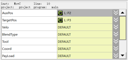
Middle position: The position of the auxiliary point in the middle of the arc.
Target position: The final position of the arc.
Target speed: The running speed of command.
− When setting it to “DEFAULT”, the default value V4000 will be used.
− When it is set to SPEED variable, you can select the system pre-defined one, or create it by yourself.
Transition type: The way of transition when the robot approaches the endpoint.
− DEFAULT: Default, i.e. no transition parameter is set in the command. If the SetBlendParam parameter is used in the program, the transition mode operates as per the globally set transition parameter.
− FINE: Equivalent in effect to DEFAULT.
− RELATIVE: Relative transition. The transition parameter is a relative value that represents the percentage of the distance from the transition point to the path endpoint relative to the full length of the path.
− ABSOLUTE: Absolute transition. The transition parameter is an absolute value that represents the distance from the transition point to the endpoint of path.
Transition Value: The transition value when the robot approaches the endpoint.
− When setting it to “DEFAULT”, the default value C100 will be used.
− When it is set to ZONE variable, you can select the system pre-defined one, or create it by yourself; it means no transition when the variable value is 0; the greater the transition value, the larger the transition radius.
Tool Parameters: The tool parameters used when the robot executes the path.
− When setting it to “DEFAULT”, the tool parameters set last time will be continuously used.
− When it is set to TOOL variable, you can select the system pre-defined one, or create it by yourself.
When using a coordinate system different from the current tool parameters, the system will switch the tool parameters to the set ones. If the tool parameters of the path of current segment and the preceding/next segments change, the transition will not be supported.
Coordinate System Parameters: The coordinate system parameters used by the robot when executing the path.
− When setting it to “DEFAULT”, the tool coordinate system set last time will be continuously used.
− When it is set to USERCOOR variable, you can select the system pre-defined one, or create it by yourself. When a coordinate system different from the current one is used, the system will switch the coordinate system to the set one.
− When it is set to external tool coordinates, the motion of robot is relative to the external tool coordinates, and the target speed of command is relative to the external tool coordinates. External TCP functions support only the transition between the reference coordinate system is the same external tool coordinates.
− When setting it to the positioner coordinates, the robot’s motion is relative to the positioner coordinates, and the target speed of command is relative to the positioner flange. The POSITIONER function supports only the transition between the same positioner.
Workpiece load: The workpiece load parameter used by the robot when executing the path.
− It is set to “DEFAULT”, which means to continue to use the workpiece load parameters set last time.
− When it is set to PAYLOAD variable, you can select the system pre-defined one, or create it by yourself; when a load parameter different from the current workpiece load parameter is used, the system will switch the workpiece load parameter to the set parameter. If the tool parameters of the path of current segment and the preceding/next segments change, the transition will not be
supported.
Rate type: Whether the robot's commanded speed is affected by the global multiplier of the programming pendant when executing this path.
− DEFAULT: Same as GOVRON, i.e. the commanded speed is affected by the global multiplier of the programming pendant.
− GOVRON: The commanded speed is affected by the global multiplier of the programming pendant.
− GOVROFF: The commanded speed is not affected by the global multiplier of the programming pendant.
AddDo: The robot can perform IO operation after executing this command.
− NULL: No operation.
− IO Command: Executing IO operation.
Figure 6-5 Key points of MovC arc
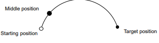
This command must satisfy:
When the end of the robot TCP performs a full circular motion, two MovC commands must be executed or the MovCircle command must be used.
MovCircle - Circular motion command
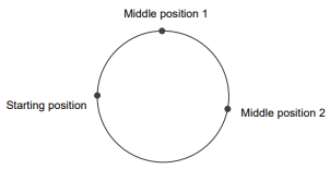
MovCircle command means that the robot TCP point moves in a full circle from the start position to the start position through the auxiliary point 1 and auxiliary point 2 positions, with the pose remaining constant during the movement.
Figure 6-6 Parameter editing interface of MovCircle
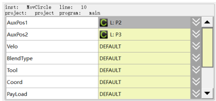
Middle Position 1: The position 1 of the middle auxiliary point of the full circle, which is used to determine the size and movement direction of the arc. The pose of this point will not affect the final trajectory.
Middle Position 2: The position 2 of the middle auxiliary point of the full circle, which is used to determine the size and movement direction of the arc. The pose of this point will not affect the final trajectory.
Target speed: The running speed of command.
− When setting it to “DEFAULT”, the default value V4000 will be used.
− When it is set to SPEED variable, you can select the system pre-defined one, or create it by yourself.
Transition type: The way of transition when the robot approaches the endpoint.
− DEFAULT: Default, i.e. no transition parameter is set in the command. If the SetBlendParam parameter is used in the program, the transition operates according to the globally set transition parameter.
− FINE: Equivalent in effect to DEFAULT.
− RELATIVE: Relative transition, where the transition parameter is a relative value that represents the distance from the transition point to the end of the track as a percentage of the full trajectory path.
− ABSOLUTE: Absolute transition, where the transition parameter is an absolute value indicating the distance from the transition point to the endpoint of path.
Transition Value: The transition value when the robot approaches the endpoint.
− When setting it to “DEFAULT”, the default value C100 will be used.
− When it is set to ZONE variable, you can select the system pre-defined one, or create it by yourself; it means no transition when the variable value is 0; the greater the transition value, the larger the transition radius.
Tool Parameters: The tool parameters used when the robot executes the path.
− When setting it to “DEFAULT”, the tool parameters set last time will be continuously used.
− When it is set to TOOL variable, you can select the system pre-defined one, or create it by yourself.
When using a coordinate system different from the current tool parameters, the system will switch the tool parameters to the set ones. If the tool parameters of the path of current segment and the preceding/next segments change, the transition will not be supported.
Coordinate System Parameters: The coordinate system parameters used by the robot when executing the path.
− When setting it to “DEFAULT”, the tool coordinate system set last time will be continuously used.
− When it is set to USERCOOR variable, you can select the system pre-defined one, or create it by yourself. When a coordinate system different from the current one is used, the system will switch the coordinate system to the set one.
− When it is set to external tool coordinates, the motion of robot is relative to the external tool coordinates, and the target speed of command is relative to the external tool coordinates. External TCP functions support only the transition between the reference coordinate system is the same external tool coordinates.
− When setting it to the positioner coordinates, the robot’s motion is relative to the positioner coordinates, and the target speed of command is relative to the positioner flange. The POSITIONER function supports only the transition between the same positioner.
Workpiece load: The workpiece load parameter used by the robot when executing the path.
− It is set to “DEFAULT”, which means to continue to use the workpiece load parameters set last time.
− When it is set to PAYLOAD variable, you can select the system pre-defined one, or create it by yourself; when a load parameter different from the current workpiece load parameter is used, the system will switch the workpiece load parameter to the set parameter. If the tool parameters of the path of current segment and the preceding/next segments change, the transition will not be supported.
Rate type: Whether the robot’s commanded speed is affected by the global multiplier of the programming pendant when executing this path.
− DEFAULT: Same as GOVRON, i.e. the commanded speed is affected by the global multiplier of the programming pendant.
− GOVRON: The commanded speed is affected by the global multiplier of the programming pendant.
− GOVROFF: The commanded speed is not affected by the global multiplier of the programming pendant.
AddDo: The robot can perform IO operation after executing this command.
− NULL: No operation.
− IO Command: Executing IO operation.
Figure 6-7 Key points of MovCircle full circle
MovJHand – Left and Right Hand Motion Commands
This motion instruction is used to move the joints (point to point) to the end position with the specified left and right hand systems, and is only applicable to SCARA models.
Difference between this instruction and Hand instruction.
The Hand instruction is a setup instruction. After the Hand instruction is run, the subsequent motion instructions (e.g., MovJ) move with the hand system it sets up; the MovJHand instruction is a motion instruction.
MovJHand is a motion instruction that performs PTP motion with the hand system specified in the instruction.
If Hand (e.g. lefty) instruction is followed by MovJHand (P1, e.g. Righty), this MovJHand moves in the right hand system.
Figure 6-8 MovJHand Parameter Editing Interface
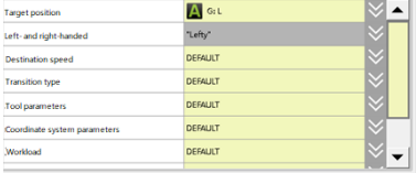
Target position: the end position of the instruction.
- When "APOS" is set, the coordinate value of each axis in the joint space.
- When "CPOS" is set, the position of TCP point in Cartesian coordinate system. The target position depends on the configuration of confdata. If the value of mode parameter is set to -1, the end position is not limited by the value of confdata, and the destination is reached by the optimal solution.
Left- and right-handed settings: left- and right-handed type mode for the end position.
- Lefty: left hand setting.
- Righty: right hand setting.
- Change: The opposite of the point position mode hand system.
Destination speed: The speed at which the command runs.
- Setting to "DEFAULT" indicates that the default value of V4000 is used.
- If you set it as a SPEED variable, you can choose the system predefined value or create your own.
Transition type: the type of transition when the robot approaches the end point.
- DEFAULT: Default, i.e. no transition parameter is set in the instruction. If the global transition parameter (SetBlendParam) is used in the program, the transition method runs according to the globally set transition parameter.
- FINE: the effect is the same as DEFAULT.
- RELATIVE: Relative transition, the transition parameter is a relative value, indicating the percentage of the distance from the transition point to the end of the trajectory relative to the length of the whole section of the trajectory.
- ABSOLUTE: Absolute transition, the transition parameter is an absolute value, indicating the distance from the transition point to the end of the trajectory.
Transition value: the transition value when the robot is approaching the end point.
- Set to "DEFAULT" to use the default value of C100.
- If the value is set to "ZONE", it can be predefined by the system or created by yourself; where: when the value of the variable is 0, it means that there is no transition, and the larger the transition value is, the larger the transition radius is.
Workload: the workload parameter used by the robot to execute the trajectory.
- Setting it to "DEFAULT" means that the most recent workload parameter is used.
- When set as PAYLOAD variable, it can be predefined by the system or created by yourself; if you use a load parameter different from the current workpiece load parameter, the system will switch the workpiece load parameter to the set workpiece load parameter. The system will switch the workpiece load parameter to the set workpiece load parameter when using a load parameter that is different from the current workpiece load parameter.
AddDo: The robot performs IO operation after executing this instruction.
MovJRel - Relative offset command
The MovJ interpolation relative offset command. It works by taking the current robot position or the target position of the previous motion command as the starting point, and then perform the robot motion operation.
Unlike the commands such as MovJ, the target relative position value used by this command cannot be obtained through teaching. User needs to create a new joint relative position variable in the list of variables before, and then select it from the drop-down list.
Figure 6-9 Parameter editing interface of MovJRel
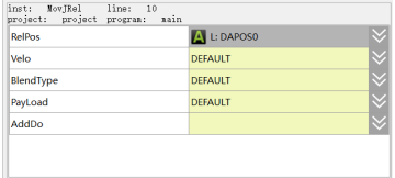
Target Relative Position: The position increment the robot will move when executing this command.
Target speed: The running speed of command.
− When setting it to “DEFAULT”, the default value V4000 will be used.
− When it is set to SPEED variable, you can select the system pre-defined one, or create it by yourself.
Transition type: The way of transition when the robot approaches the endpoint.
− DEFAULT: Default, i.e. no transition parameter is set in the command. If the SetBlendParam parameter is used in the program, the transition mode operates as per the globally set transition parameter.
− FINE: Equivalent in effect to DEFAULT.
− RELATIVE: Relative transition. The transition parameter is a relative value that represents the percentage of the distance from the transition point to the path endpoint relative to the full length of the path.
− ABSOLUTE: Absolute transition. The transition parameter is an absolute value that represents the distance from the transition point to the endpoint of path.
Transition Value: The transition value when the robot approaches the endpoint.
− When setting it to “DEFAULT”, the default value C100 will be used.
− When it is set to ZONE variable, you can select the system pre-defined one, or create it by yourself; it means no transition when the variable value is 0; the greater the transition value, the larger the transition radius.
Workpiece load: The workpiece load parameter used by the robot when executing the path.
− It is set to “DEFAULT”, which means to continue to use the workpiece load parameters set last time.
− When it is set to PAYLOAD variable, you can select the system pre-defined one, or create it by yourself; when a load parameter different from the current workpiece load parameter is used, the system will switch the workpiece load parameter to the set parameter. If the tool parameters of the path of current segment and the preceding/next segments change, the transition will not be supported.
AddDo: Robot will perform IO operation after executing this command.
MovLRel-Interpolation relative offset command
The MovJ interpolation relative offset command. It works by taking the current robot position or the target position of the previous motion command as the starting point, and then performs an offset motion relative to the coordinate system or tool.
Unlike the commands such as MovL, the target relative position value used by this command cannot be obtained through teaching. User needs to create a new joint relative position variable in the list of variables before, and then select it from the drop-down list.
Figure 6-10 Parameter editing interface of MovJRel
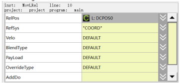
Target Relative Position: The position increment the robot will move when executing this command.
Reference Coordinates: coordinate system offset or tool offset selection;
− Coord: offset relative to the current user coordinates;
− Tool: offset relative to the tool coordinates, i.e. translation or rotation with reference to Tx, Ty, Tz.
Target speed: The running speed of command.
− When setting it to “DEFAULT”, the default value V4000 will be used.
− When it is set to SPEED variable, you can select the system pre-defined one, or create it by yourself.
Transition type: The way of transition when the robot approaches the endpoint.
− DEFAULT: Default, i.e. no transition parameter is set in the command. If the SetBlendParam parameter is used in the program, the transition mode operates as per the globally set transition parameter.
− FINE: Equivalent in effect to DEFAULT.
− RELATIVE: Relative transition. The transition parameter is a relative value that represents the percentage of the distance from the transition point to the path endpoint relative to the full length of the path.
− ABSOLUTE: Absolute transition. The transition parameter is an absolute value that represents the distance from the transition point to the endpoint of path.
Transition Value: The transition value when the robot approaches the endpoint.
− When setting it to “DEFAULT”, the default value C100 will be used.
− When it is set to ZONE variable, you can select the system pre-defined one, or create it by yourself; it means no transition when the variable value is 0; the greater the transition value, the larger the transition radius.
Workpiece load: The workpiece load parameter used by the robot when executing the path.
− It is set to “DEFAULT”, which means to continue to use the workpiece load parameters set last time.
− When it is set to PAYLOAD variable, you can select the system pre-defined one, or create it by yourself; when a load parameter different from the current workpiece load parameter is used, the system will switch the workpiece load parameter to the set parameter. If the tool parameters of the path of current segment and the preceding/next segments change, the transition will not be supported.
Rate type: Whether the robot’s commanded speed is affected by the global multiplier.
− DEFAULT: Same as GOVRON, i.e. the commanded speed is affected by the global multiplier of the programming pendant.
− GOVRON: The commanded speed is affected by the global multiplier of the programming pendant.
− GOVROFF: The commanded speed is not affected by the global multiplier of the programming pendant.
AddDo: Robot will perform IO operation after executing this command.
MovJOffset – Offset motion command of joint space
In contrast to the MovLOffset command, the MovJOffset command performs offset motion with MovJ motion and the target relative position supports both types of DAPOS and DCPOS.
In contrast to the MovJRel command, the starting position specified by the MovJOffset command is not limited to the position of the current robot or the target position of the previous motion command, and can be offset relative to the coordinates or tool.
Figure 6-11 Parameter editing interface of MovJOffset
Reference position: the starting point of the offset movement (APOS or CPOS);
Target relative position: position increment in which the robot is to move when this command is executed (DAPOS or DCPOS);
Reference Coordinates: Coordinates offset or tool offset selection. Where, "Coord" means offset relative to the current user coordinates and "Tool" means offset relative to the tool coordinates, i.e. translation or rotation with reference to Tx, Ty, Tz;
Tool parameters: information about the tool to which the reference position belongs;
Coordinate system parameter: information about the coordinate system to which the reference position belongs;
Target speed: the commanded run speed (SPEED type variable), where only the per parameter is absolutely valid for this command;
Transition type: The way of transition when the robot approaches the endpoint. RELATIVE: Relative transition. The transition parameter is a relative value that represents the percentage of the distance from the transition point to the path endpoint relative to the full length of the path. ABSOLUTE: Absolute transition. The transition parameter is an absolute value that represents the distance from the transition point to the endpoint of path.
Transition value: the transition value (variable of type ZONE) at which the robot approaches the end, where the per parameter is valid for relative transition types and the dis parameter is valid for absolute transition types;
Workpiece load: The workpiece load parameter used by the robot when executing the path.
AddDo: Robot will perform IO operation after executing this command.
MovJOffsetC – Joint space offset motion instruction
Same function as MovJOffset instruction, the difference is that the relative position of the target is changed from DCPOS type variable to four real type constants, X increment, Y increment, Z increment and A increment.
Figure 6-12 MovJOffsetC Parameter Editing Interface
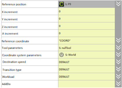
X increment: the position increment in the X direction that the robot is to move when this instruction is executed.
Y increment: the position increment in the Y direction that the robot will move when executing this instruction.
Z increment: the position increment the robot is to move in Z direction when executing this instruction.
A increment: the rotational increment that the robot will move in the A direction when executing this instruction;
Reference coordinate system: coordinate system offset or tool offset selection. Among them, "Coord" means offset relative to the current user coordinate system; "Tool" means offset relative to the tool coordinate system, i.e. reference Tx, Ty, Tz translation or rotation.
Tool parameter: information of the tool to which the reference position belongs.
Coordinate system parameter: information of the coordinate system to which the reference position belongs.
Target speed: the speed at which the instruction runs (variable of type SPEED), where only the per parameter is absolutely valid for this instruction.
Transition type: the transition mode when the robot approaches the end point; RELATIVE: relative transition, the transition parameter is a relative value, indicating the percentage of the distance from the transition point to the end point of the trajectory relative to the length of the whole section of the trajectory; ABSOLUTE: absolute transition, the transition parameter is an absolute value, indicating the distance from the transition point to the end point of the trajectory.
Transition value: the transition value (variable of type ZONE) when the robot approaches the end point, where the per parameter corresponds to a relative transition type valid and the dis parameter corresponds to an absolute transition type valid.
Workload: the workload parameter used by the robot to execute the trajectory.
AddDo: the robot performs an IO operation after executing this instruction.
MovLOffset - Linear offset motion command
MovL Interpolation Relative Offset command. This command specifies a reference position as the starting position for an offset movement relative to the coordinates or tool.
It differs from MovLRel only in that it specifies the starting point of the offset movement, not necessarily the current position or the endpoint of the previous command, and all other functions are the same.
Figure 6-13 Parameter editing interface of MovJOffset
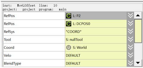
The new command parameters compared to MovLRel are as follows:
Reference position: The starting point of the offset movement (APos or CPos).
Tool parameters: Information on the tool to which the reference position belongs.
Coordinate system parameters: Information on the coordinate system to which the reference position belongs.
MovLOffsetC – Linear offset motion command
The function is the same as that of MovLOffset instruction, but the difference is that the relative position of the target is changed from a variable of DCPOS type to four real type constants, X increment, Y increment, Z increment and A increment.
Figure 6-14 MovLOffsetC Parameter Editing Interface
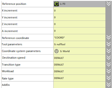
Reference position: the starting point of offset movement (APOS or CPOS).
X increment: the position increment that the robot will move in X direction when executing this instruction.
Y increment: the position increment that the robot has to move in the Y direction when executing this instruction.
Z increment: the position increment the robot is to move in Z direction when executing this instruction.
A increment: the rotational increment that the robot will move in the A direction when executing this instruction.
Reference coordinate system: coordinate system offset or tool offset selection. Among them, "Coord" means offset relative to the current user coordinate system; "Tool" means offset relative to the tool coordinate system, i.e. reference Tx, Ty, Tz translation or rotation.
Tool parameter: information of the tool to which the reference position belongs.
Coordinate system parameter: information of the coordinate system to which the reference position belongs.
Target speed: the speed at which the instruction runs (variable of type SPEED), where only the per parameter is absolutely valid for this instruction.
Transition type: the transition mode when the robot approaches the end point; RELATIVE: relative transition, the transition parameter is a relative value, indicating the percentage of the distance from the transition point to the end point of the trajectory relative to the length of the whole section of the trajectory; ABSOLUTE: absolute transition, the transition parameter is an absolute value, indicating the distance from the transition point to the end point of the trajectory.
TRANSITION VALUE: the transition value (variable of type ZONE) when the robot approaches the end point, where the per parameter corresponds to a relative transition type valid and the dis parameter corresponds to an absolute transition type valid.
Workload: the workload parameter used by the robot to execute the trajectory.
AddDo: the robot performs an IO operation after executing this instruction.
Trigger command does not support single-step mode by default, you can modify the "single-step enable" parameter in the main interface according to the order of [General Settings] -> [Program Settings] to enable/disable the single-step mode of trigger command.
MovJSearch - Searching command (MovJ)
A search command, which performs IO detection or torque detection when executing the MovL command.
When the search condition is IO detection and the value of index IO reaches the triggered value, stop running the command and continue to execute the next command with the interrupt return value set to 1.
When the search condition is torque detection and the value of the index axis torque reaches the triggered value, stop running the command and continue to execute the next command, with the interrupt return value set to X.
If there is no interruption during the command execution, set the interrupt return value to 0.
Figure 6-15 Parameter editing interface of MovJSearch
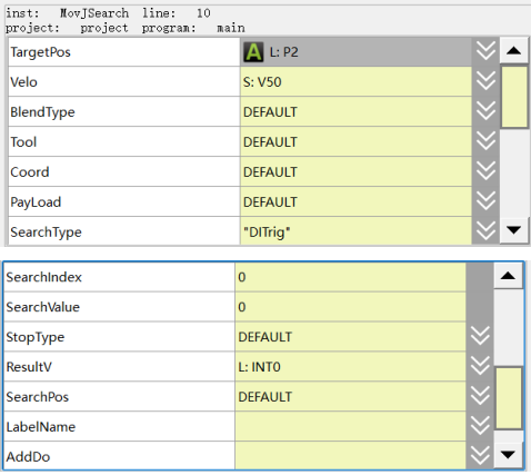
Target position: The final position of the command (the position point of APOS or CPOS).
Target speed: The speed at which the command position is run (SPEED variable). Only the PER parameter is absolutely valid for this command.
Tool parameter: Information on the tool.
Coordinate system parameter: Cartesian coordinate system to which the target position refers.
Workload: Information on the workload.
Transition type: The way of transition when the robot approaches the endpoint.
− DEFAULT: Default, i.e. no transition parameter is set in the command. If the SetBlendParam parameter is used in the program, the transition operates still works the way FINE does.
− FINE: Equivalent in effect to DEFAULT.
Note: MovJSearch does not support transition planning with the next motion command in the current version.
Type of detection:
− DITrig: Physical digital IO input detection.
− AITrig: Physical analogue IO input detection.
− SIMDITrig: Virtual digital IO input detection.
− SIMAITrig: Virtual analogue IO input detection.
− TorqTrig: Torque detection.
Trigger index:
− For DITrig/SIMDITrig/ AITrig/ SIMAITrig, this parameter indicates the IO port number to be detected.
− For TorqTirg, this parameter indicates the axis number to be detected.
Trigger value:
− For DITrig/SIMDITrig/ AITrig/ SIMAITrig, the threshold for IO detection.
− For InputTrig, the threshold for IO detection.
For TorqTirg, the threshold value for torque detection, in thousandths of the nominal torque.
STOP type: The way to stop when a signal is detected.
− DEFAULT: Stops immediately;
− HARDSTOP: Stops immediately;
− SOFTSTOP: Stop at reduced speed.
Decel Factor: The value is valid when "SOFTSTOP" is selected as "Stop Type". It is used to adjust the Decel/Accel factor, the greater the value, the faster the deceleration.
AddDo: Robot will perform IO operation after executing this command.
Returned value: The returned value determines whether there is an interrupt during the run. 0: not detected; 1:
Searching succeeded; 2: Signal is detected at the start of the movement
Position of successful search: Returns the coordinate position of the robot at the moment of the interrupt. (APOS type). This parameter can be defaulted.
Label name to jump to in case of a search failure: The name of the label to which the program pointer will jump in case of a search failure, which is the name of a label already taught in the current program (e.g. "Start:"). This parameter can be defaulted.
Note
Transition planning with the next motion command is not supported in the current version of MovJSearch.
Example 1:

MovLSearch - Search command (MovL)
The Search Ccommand refers to IO detection or torque detection while executing this MovL command, which is similar to MovJSearch.
When the search condition is of IO detection and the value of the indexed IO reaches the trigger value, stop running this command and continue to execute the next command with the interrupt return value set to 1.
When the search condition is of torque detection and the value of the index axis torque reaches the trigger value, stop running the command and continue to execute the next command, with the interrupt return value set to 1.
If there is no interrupt during the command running, set the interrupt return value to 0.
Figure 6-16 Parameter editing interface of MovLSearch
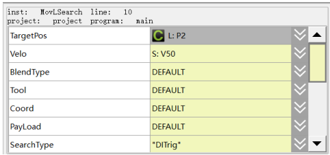
Target position: The final position of the command (the position point of APOS or CPos).
Target speed: The position running speed of command (SPEED variable), where the parameter tcp is valid for the command linear speed and ori is valid for the pose speed (and neither can be 0).
Transition type: The way of transition when the robot approaches the endpoint.
− DEFAULT: Default, i.e. no transition parameter is set in the command. If the SetBlendParam parameter is used in the program, the transition operates still works the way FINE does.
− FINE: Equivalent in effect to DEFAULT.
Note: MovJSearch does not support transition planning with the next motion command in the current version.
Type of detection:
− DITrig: Physical digital IO input detection.
− AITrig: Physical analogue IO input detection.
− SIMDITrig: Virtual digital IO input detection.
− SIMAITrig: Virtual analogue IO input detection.
Tool parameter: Information on the tool.
Coordinate system parameter: Cartesian coordinate system to which the target position refers.
Workload: Information on the workload.
Trigger index:
For DITrig/SIMDITrig/ AITrig/ SIMAITrig, this parameter indicates the IO port number to be detected.
For TorqTirg, this parameter indicates the axis number to be detected.
Trigger value:
For DITrig/SIMDITrig/ AITrig/ SIMAITrig, the threshold for IO detection.
For InputTrig, the threshold value for torque detection, in thousandths of nominal torque.
STOP type: The way to stop when a signal is detected.
− DEFAULT: Stops immediately;
− HARDSTOP: Stops immediately;
− SOFTSTOP: Stop at reduced speed.
Decel Factor: The value is valid when "SOFTSTOP" is selected as "Stop Type". It is used to adjust the Decel/Accel factor, the greater the value, the faster the deceleration.
Returned value: The returned value determines whether there is an interrupt during the run. 0: not detected; 1: Searching succeeded; 2: Signal is detected at the start of the movement
Position of successful search: Returns the coordinate position of the robot at the moment of the interrupt. (CPOS type). This parameter can be defaulted.
Label name to jump to in case of a search failure: The name of the label to which the program pointer will jump in case of a search failure, which is the name of a label already taught in the current program (e.g. "Start:"). This parameter can be defaulted.
AddDo: Robot will perform IO operation after executing this command.
Note
Transition planning with the next motion command is not supported in the current version of MovLSearch.
Example 1:

MovLW - Weave command
Weave command, which performs the arc swinging motion in the forward direction based on the set swing frequency and amplitude.
Figure 6-17 Parameter editing interface of MovLW
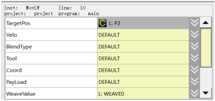
Target position: The final position of the command (the position point of APOS or CPos).
Select an existing point from the drop-down list or create and teach a new variable in the pop-up dialog box.
Target speed: The running speed of command.
− When setting it to “DEFAULT”, the default value V4000 will be used.
− When it is set to SPEED variable, you can select the system pre-defined one, or create it by yourself.
Transition type: The way of transition when the robot approaches the endpoint.
− DEFAULT: Default, i.e. no transition parameter is set in the command. If the SetBlendParam parameter is used in the program, the transition mode operates as per the globally set transition parameter.
− FINE: Equivalent in effect to DEFAULT.
− RELATIVE: Relative transition. The transition parameter is a relative value that represents the percentage of the distance from the transition point to the path endpoint relative to the full length of the path.
− ABSOLUTE: Absolute transition. The transition parameter is an absolute value that represents the distance from the transition point to the endpoint of path.
Transition Value: The transition value when the robot approaches the endpoint.
− When setting it to “DEFAULT”, the default value C100 will be used.
− When it is set to ZONE variable, you can select the system pre-defined one, or create it by yourself;
it means no transition when the variable value is 0; the greater the transition value, the larger the transition radius.
Tool Parameters: The tool parameters used when the robot executes the path.
− When setting it to “DEFAULT”, the tool parameters set last time will be continuously used.
− When it is set to TOOL variable, you can select the system pre-defined one, or create it by yourself.
When using a coordinate system different from the current tool parameters, the system will switch the tool parameters to the set ones. If the tool parameters of the path of current segment and the preceding/next segments change, the transition will not be supported.
Coordinate System Parameters: The coordinate system parameters used by the robot when executing the path.
− When setting it to “DEFAULT”, the tool coordinate system set last time will be continuously used.
− When it is set to USERCOOR variable, you can select the system pre-defined one, or create it by yourself. When a coordinate system different from the current one is used, the system will switch the coordinate system to the set one.
− When setting it to the positioner coordinates, the robot’s motion is relative to the positioner coordinates, and the target speed of command is relative to the positioner flange. The POSITIONER function supports only the transition between the same positioner.
Workpiece load: The workpiece load parameter used by the robot when executing the path.
− It is set to “DEFAULT”, which means to continue to use the workpiece load parameters set last time.
− When it is set to PAYLOAD variable, you can select the system pre-defined one, or create it by yourself; when a load parameter different from the current workpiece load parameter is used, the system will switch the workpiece load parameter to the set parameter. If the tool parameters of the path of current segment and the preceding/next segments change, the transition will not be supported.
Swinging arc variable: The weaving parameter.
The swing frequency, amplitude, stop time, rotation, etc. can be set.
Rate type: Whether the robot’s commanded speed is affected by the global multiplier of the programming pendant when executing this path.
− DEFAULT: Same as GOVRON, i.e. the commanded speed is affected by the global multiplier of the programming pendant.
− GOVRON: The commanded speed is affected by the global multiplier of the programming pendant.
− GOVROFF: The commanded speed is not affected by the global multiplier of the programming pendant.
AddDo: Robot will perform IO operation after executing this command.
− NULL: No operation.
− IO command: Performs IO operations.
Note
The WEAVE variable has the following parameters:
⚫ Type: Weave type of robot. It is a sine Weave when the value is 1, and is a triangular Weave when the value is 2.
⚫ Freq: The frequency when the robot weaves, in Hz.
⚫ Amp_L: The left amplitude when the robot weaves, in mm.
⚫ Amp_R: The right amplitude when the robot weaves, in mm.
⚫ StopTime_L: The time when robot stops at wave peak. It refers to the time in ms at which the weaving stops when it reaches the left amplitude.
⚫ StopTime_C: The time when robot stops at the middle. It refers to the time in ms at which the weaving stops when it reaches the middle position.
⚫ StopTime_R: The time when robot stops at wave trough. It refers to the time in ms at which the weaving stops when it reaches the right amplitude.
⚫ RotAngle_X: The rotating angle of the weaving reference plane around the weaving direction. This parameter is used to determine the final weaving plane, in deg.
⚫ RotAngle_Z: The rotating angle around the normal vector of the weaving plane, which determines the shape of the sine weave, in deg.
Caution
⚫ The normal vector of the plane determined by the motion path and the Tz direction of tool coordinates, and the plane formed by the motion path is the reference plane for weaving.
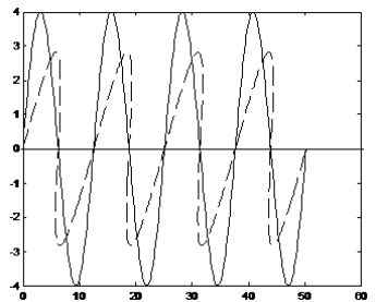
⚫ The function of RotAngle_Z is in the figure below: it is indicated by a solid line if RotAngle_Z=0 is a solid line, and a dotted line if it is not 0.
MovCW
Similar to MovLW.
MovCircleW
Similar to MovLW.
MovH - Helical motion command
The Helical motion command, through which the TCP point of the robot can perform Helical motion to the target position. If the start and end postures of the motion are different, the posture will rotate to the ending posture synchronously with the position.
Figure 6-18 Parameter editing interface of MovH
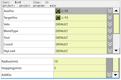
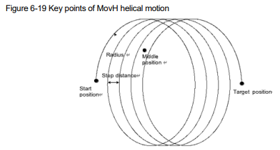
Middle position: The position of the helical middle auxiliary point. The auxiliary point is used to determine the helical plane and the helical direction (precession in clockwise and counterclockwise). The helical movement may not pass through the auxiliary point
Target position: Helical end position
Target speed: the speed at which the command position is run, where the parameter tcp is valid for the linear speed of the command and ori is valid for the posture speed. The maximum path linear speed of the helical line is 0.25 times the maximum system speed
Transition type: Transition not supported
Tool Parameters: The tool parameters used when the robot executes the path.
− When setting it to “DEFAULT”, the tool parameters set last time will be continuously used.
− When it is set to TOOL variable, you can select the system pre-defined one, or create it by yourself.
When using a coordinate system different from the current tool parameters, the system will switch the tool parameters to the set ones. If the tool parameters of the path of current segment and the preceding/next segments change, the transition will not be supported.
Coordinate System Parameters: The coordinate system parameters used by the robot when executing the path.
− When setting it to “DEFAULT”, the tool coordinate system set last time will be continuously used.
− When it is set to USERCOOR variable, you can select the system pre-defined one, or create it by yourself. When a coordinate system different from the current one is used, the system will switch the coordinate system to the set one.
− When setting it to the positioner coordinates, the robot’s motion is relative to the positioner coordinates, and the target speed of command is relative to the positioner flange. The POSITIONER function supports only the transition between the same positioner.
Workpiece load: The workpiece load parameter used by the robot when executing the path.
− It is set to “DEFAULT”, which means to continue to use the workpiece load parameters set last time.
When it is set to PAYLOAD variable, you can selected the system pre-defined one, or create it by yourself; when a load parameter different from the current workpiece load parameter is used, the system will switch the workpiece load parameter to the set parameter. If the workpiece load of the path of current segment and the preceding/next segments change, the transition will not be supported.
Radius: Helical line radius, in mm
Stepping distance: The stepping distance when the helical line makes one revolution, in mm
AddDo: The robot can perform IO operations after executing this comman
Figure 6-19 Key points of MovH helical motion
Note
For Helical motion, the transition and WaitFinish are not supported.
Example:

MovArch - Arch-shaped motion command
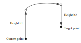
MovArch is an arch-shaped motion command. The motion process is as follows: first, elevate the robot to a height of h1 at the current point, then move it to a height of h2 from the target point, and finally descend it again to a height of h2 to reach the target point. This is an arch-shaped motion, which is a point-to-point motion. When the robot moves directly to the target point, it is automatically elevated to a height outside the obstacle and then moves to the target point to improve safety and operability.
Figure 6-20 Motion path
Note
This command is only for scara model currently.
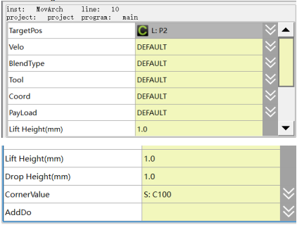
Figure 6-21 Parameter editing interface of MovArch
Target position: The final position of the command (the position point of APOS or CPOS).
Select an existing point from the drop-down list, or create a new a variable in the pop-up dialog box for teaching.
Target speed: The running speed of the command (SPEED variable).
Transition type: The way of transition when the robot approaches the endpoint.
− DEFAULT: Default, i.e. no transition parameter is set in the command. If the SetBlendParam parameter is used in the program, the transition operates according to the globally set transition parameter.
− FINE: Equivalent in effect to DEFAULT.
− RELATIVE: Relative transition, where the transition parameter is a relative value that represents the distance from the transition point to the end of the track as a percentage of the full trajectory path.
− ABSOLUTE: Absolute transition, where the transition parameter is an absolute value indicating the distance from the transition point to the endpoint of path.
Transition value: The transition value when the robot approaches the endpoint (ZONE variable).
− When setting it to “DEFAULT”, the default value C100 will be used.
− When it is set to ZONE variable, you can select the system pre-defined one, or create it by yourself; it means no transition when the variable value is 0; the greater the transition value, the larger the transition radius.
Tool Parameters: The tool parameters used when the robot executes the path.
− When setting it to “DEFAULT”, the tool parameters set last time will be continuously used.
− When it is set to TOOL variable, you can select the system pre-defined one, or create it by yourself.
When using a coordinate system different from the current tool parameters, the system will switch the tool parameters to the set ones. If the tool parameters of the path of current segment and the preceding/next segments change, the transition will not be supported.
Coordinate System Parameters: The coordinate system parameters used by the robot when executing the path.
− When setting it to “DEFAULT”, the tool coordinate system set last time will be continuously used.
− When it is set to USERCOOR variable, you can select the system pre-defined one, or create it by yourself. When a coordinate system different from the current one is used, the system will switch the coordinate system to the set one.
Workpiece load: The workpiece load parameter used by the robot when executing the path.
− It is set to “DEFAULT”, which means to continue to use the workpiece load parameters set last time.
− When it is set to PAYLOAD variable, you can select the system pre-defined one, or create it by yourself; when a load parameter different from the current workpiece load parameter is used, the system will switch the workpiece load parameter to the set parameter. If the tool parameters of the path of current segment and the preceding/next segments change, the transition will not be
supported.
Lifting height: The height that the end of robot needs to elevate when performing arching motion, as shown in Figure h1.
Descending height: The height at which the end of the robot descends when executing an arching motion, as in Figure h2.
Rotating angle value: The transition parameters (ZONE variables) when the robot performs an arcing motion.
AddDo: Robot will perform IO operation after executing this command.
− NULL: No operation.
− IO command: Execute IO operations.
Example:

MovLArch – Linear arch-shaped motion command
The linear arch-shaped motion command. In this command, the robot uses the current position as the starting position and makes an elevating motion, then moves above the target point in a MovL motion and finally descends to the target point.
As shown in the diagram below: First, the robot elevates h1 at the current point, then moves to a height of h2 from the target point, and finally descends h2 again to reach the target point. This is a cycle of arching motion.
This arching motion is a spatial linear motion mode. When the robot moves directly to the target point, it is automatically elevated to a height outside the obstacle and then moves to the target point to improve safety and operability
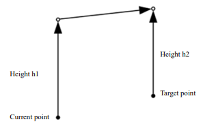
Figure 6-22 MovLArch parameters
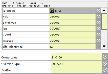
Target position: The final position of the command (the position point of APOS or CPOS).
Target speed: the speed at which the command is run;
Transition type: the way of transition when the robot approaches the endpoint; DEFAULT.
Transition value: the value of the transition when the robot approaches the end point;
Tool parameters: the tool parameters used by the robot to execute the path;
Coordinate system parameters: the parameters of the coordinate system used by the robot to execute the path;
Workpiece load: the workpiece load parameter used by the robot to execute the path;
Lifting height: The height that the end of robot needs to elevate when performing arching motion, as shown in Figure h1;
Descending height: The height at which the end of the robot descends when executing an arching motion, as in Figure h2;
Rotating angle value: The transition parameters when the robot performs an arcing motion;
Rate type: whether the commanded speed is affected by the global multiplier of the teach pendant when the robot executes this path;
AddDo: The robot can perform IO operation after executing this command.
The MovLArch command is currently only available for Scara models.
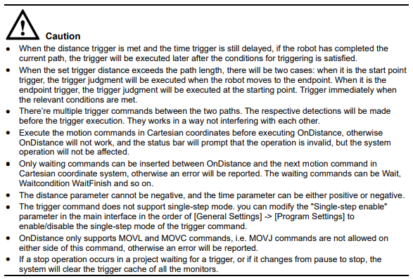
OnDistance - Distance trigger command
The distance trigger command. The controller can trigger some operations when moving a certain distance from the starting point or to the end point by not interrupting the transition, e.g. assigning values, setting IO and so on.
Figure 6-23 Parameter editing interface of OnDistance
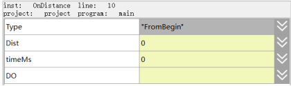
When the trigger type is set to judge from the starting point, the controller will enter the trigger waiting after the robot moves to the set distance, and after delaying the trigger time (time is positive), it will start to perform the related trigger operations.
When the trigger type is set to judge from the endpoint, the controller will enter the trigger waiting after the robot moves to the set distance, and after delaying the trigger time (time is positive), it will start to perform the related trigger operations.
When the trigger time is negative, the controller calculates in advance how long it will take before the robot moves to the set distanc. When the delay reaches the trigger time, the system will start to perform the trigger operations.
Trigger type: Specify whether the current trigger is made at a certain distance from the start point or at a distance to the endpoint.
Trigger distance: The distance parameter for the trigger. This parameter is of the REALC parameter type, i.e. it can be entered either as a constant or as a variable of the REAL type.
Trigger time: The time delayed for trigger after the trigger condition is met. This parameter is of an INTC parameter type, which can be entered as either a constant or an INT type variable. When set to a negative number, it indicates an early trigger.
Trigger operation: The robot needs to perform the trigger operations after the trigger condition is met.
Example 1: The Do operation is executed at a distance of 200ms from the starting point of the path from P1 to P2, with a delay of 100ms.

Example 2: The Do operation is executed at a distance of 200ms from the end point of the path from P1 to P2, with a delay of 100ms.

OnParameter - Distance percentage trigger command
The distance percentage trigger command. It is used to trigger some operations (e.g. assignment, setting IO and other shortcut operations) at a certain point of the linear path without interrupting the transition.
Figure 6-24 Parameter editing interface of OnParameter
When the robot moves to the set path of trigger percentage, the controller enters the trigger waiting, and it starts to execute the related trigger operation after the trigger time is delayed (time is positive).
When the trigger time is negative, the controller calculates in advance how long it will take before the robot moves to the set distanc. When the delay reaches the trigger time, the system will start to perform the trigger operations.
Path percentage: The percentage of paths that need to be triggered.
Trigger time: The time delayed for trigger after the trigger condition is met. This parameter is of an INTC parameter type, which can be entered as either a constant or an INT type variable.
When set to a negative number, it indicates an early trigger.
Trigger operation: The robot needs to perform the trigger operations after the trigger condition is met.
Note
The trigger command does not support single-step mode. you can modify the "Single-step enable" parameter in the main interface in the order of [General Settings] -> [Program Settings] to enable/disable the single-step mode of the trigger command.
Example:
Example: Execute a Do operation with a delay of 500ms from P1 to P2 at a path distance of 60%.

6.2 Control commands
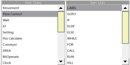
The list of control commands is shown in Figure 6-25.
Figure 6-25 List of control commands
LABEL - Defining the jump target
Label command is used to jump target.
GOTO – JUMP command
GOTO command is used to jump to different parts of the program. The jump target is defined by the
LABEL. It is not allowed to jump from the external into the internal program blocks. The internal block may be a WHILE cycle block or an IF block.
Example:

IF- Conditional judgment command
IF command is used for jump control of the conditional judgment expression. When the result of the conditional judgment expression is TRUE, the program executes the block content under IF. Similar to the IF statement in c++. The result of the IF condition judgment expression must be of BOOL type. For every IF command, any conditional judgment block must be ended with the keyword ENDIF.
After selecting "Control Commands→ IF", you will enter the setting interface of IF statements, as shown in Figure 6-26.
Figure 6-26 IF statement setting interface
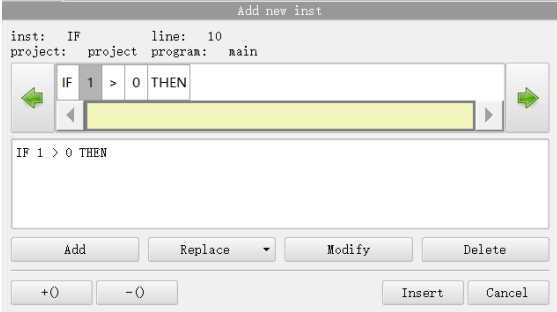
Variable A and Variable B can be set as constants or parameters: Click "Replace", and choose the constant, variable or function for replacement.
To modify the value of a variable, you can move the cursor to the variable that needs to be modified, then click "Modify", and set the value in the pop-up dialog box.
The judgment symbol is used to judge the relationship between Variable A and Variable B. If it is TRUE, the command behind THEN is executed; if it is FALSE, the command behind THEN is skipped.
Click "Add" to add a new "+" at the current position of the cursor, of which "+" denotes an operator, and "" denotes an operand.
− Click "+", then click "Modify" and select the desired operator in the pop-up soft keyboard, as shown in Figure 6-27.
Figure 6-27 Modifiable operator
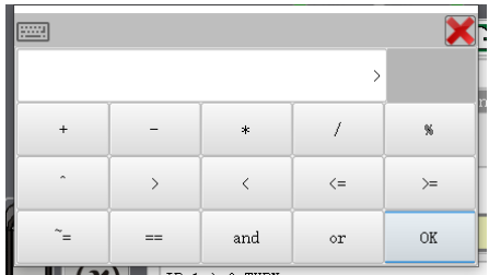
Click "", and then click "Replace" or "Modify" to change the operand to the desired constant, variable or function.
Click the operator or operand you would like to delete, and then click "Delete" to delete such operator and the subsequent operands.
Click an operator, and then click "()" to add a bracket to the operand in front of and behind the current operator. Click an operand and then click "()" to add a bracket to the current operand.
To delete the bracket, click the operator or operand, and then click "(*)" to delete the selected operator or operand response bracket.

Note
To delete an IF command, you need to click "Select Multi-line" in the program editing interface, then click the control statement between IF and END_IF, and then click "Edit → Delete" on the right menu.
When make replacement, you can select "mathematical function" or "character function". The functions are detailed in the “Mathematical Operation Functions” and “Other Functions”.
ELSIF
ELSIF relies upon the IF command. It follows closely the IF command block. When the IF logic is not established, the ELSIF logic judgment is performed.
The way to set the ELSIF expression is the same as that of the IF expression.
Followings shall be noted when using this command:
ELSIF can be added behind the IF command block, but cannot be added separately.
ELSIF can also be added behind the ELSIF command block, of which one IF command block is followed by multiple ELSIF blocks.
ELSIF can be added in a nested way, which means that IF and ELSIF commands can be added in IF or ELSIF block.
After the IF logic is TRUE, the subsequent ELSIF commands will not be executed, but executing ENDIF directly.
After the IF logic is FALSE, the subsequent ELSIF commands will be executed; and if the ELSIF logic is FALSE, the subsequent ELSIF commands will then be executed.
After the IF logic is FALSE, the subsequent ELSIF command will be executed, and the ELSIF logic will be TRUE.
The subsequent ELSIF commands will not, after execution, be executed, but executing ENDIF directly.
ELSE
ELSE command relies on the IF or ELSIF command. It is registered behind the IF or ELSIF block. The statement will be executed when the IF or ELSIF condition judgment is not established.
WHILE –Loop whenever conditions are met
WHILE command executes sub-statements in loops when the conditions are met. The loop control expression must be of BOOL type. This command must end with the keyword ENDWHILE as the loop control.
The way to set WHILE expression is the same as that of IF expression.
For example:

This command executes the cyclic motion of 100 times between two points.
FOR – for loop command
The FOR loop command consists of a 3 segments of strings, separated by commas. The command is ended with the keyword ENDFOR.
The FOR loop command executes the loop body at the end of a loop and then makes another conditional judgement. If the condition is still valid, the loop will continue to repeat, and when the condition is not valid, the current FOR loop will be jumped out.
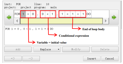
Format: FOR (variable=initial value, conditional expression, end loop body at end) DO // If the conditional expression is satisfied, the end loop body is executed; if not, the loop is jumped out directly.
…. // The code to be executed, once upon the end of each FOR.
ENDFOR
For example:

CALL - CALL command
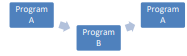
The CALL command. The current program jumps to another subroutine under the same project or to a global program under the global project, and jumps back to the current program after the subroutine is executed.
If another subroutine under the same project is program1, the command generated in the program is:

If the subroutine under the global project that needs to be called is program1, the command generated in the program is:

Figure 6-28 shows the program execution flow.
Figure 6-28 Execution flow of CALL command
RUN - Program parallel running command
The program parallel running command. It enables the robot to run other programs while running the current program (the current program continues to run while starting another program without jumping) and the running program must be in the same project. If the program to be run is program1, the command then produced in the program is:

Note
Currently, the controller supports 8 parallel running programs.
Figure 6-29 shows the program execution flow.
Figure 6-29 Execution flow of RUN command
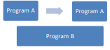
KILL – Command to stop parallel running
The command to stop parallel running. It enables the robot to stop running other programs while running the current program. The program stopped must be in the same project and in the running state. If the program that needs to be stopped is program1, the command produced in the program is:

RETURN - RETURN command
The RETURN command. In general, the program will jump to the end of the program after executing this command. If the RETURN is used in the CALL command, it will then return to the upper level program of the CALL command.
Example:

SWITCH
SWITCH-CASE logical instruction starts with SWITCH keyword and ends with ENDSWITCH, in which CASE and DEFAULT statements can be added.
After executing the SWITCH statement, find the matching CASE and jump to the corresponding CASE statement block directly;
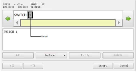
Variables: can be int, string type.
Example 1:
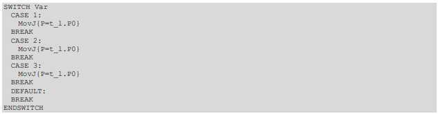
Note
SWITCH statement does not allow nested execution.
The variable type after the CASE statement must match the SWITCH type.
At least one of CASE or DEFAULT must be included between SWITCH and ENDSWITCH, and DEFAULT must come last.
If SWITCH is followed by an int type CASE supports this form CASE 1,2,3 matches any of these will execute to that CASE statement block.
SWITCH followed by a string type CASE does not support this form CASE "hello", "h1", "h3".
CASE
Can only be used in the SWITCH instruction, see SWITCH instruction.
BREAK
Can only be used in the SWITCH instruction, see SWITCH instruction.
DEFAULT
Can only be used in the SWITCH instruction, see SWITCH instruction.
...=... - Establish an expression
Establish an expression to assign a value to a variable, as shown in Figure 6-30.
Figure 6-30 How to establish an expression
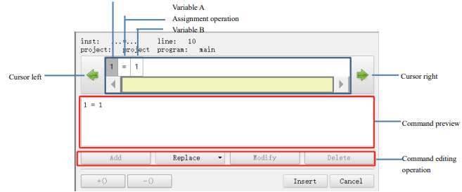
Variable A: can only be set as a variable. Click on "Replace" and choose the variable to be replaced.
Variable B: can be set to a constant or variable. Click on "Replace" and choose the constants, variables and functions to be replaced.
Assignment: Assigns the value of variable B to variable A.
Command preview: displays the entered command.
Command editing operations:
Add: move the cursor to "Variable B", and then click "Add", the expression will automatically add a new empty value, and the operator is "+" in default.
Replace: Move the cursor to the variable to be replaced and click on "Replace" to choose the constant, variable or function to be replaced.
Modify: To modify the value or operator symbol of a variable, move the cursor over the variable or operator symbol to be modified, click on "Modify" and set the value or operator symbol you wish to modify in the pop-up dialog box, as shown below:
Figure 6-31 Modifiable operator
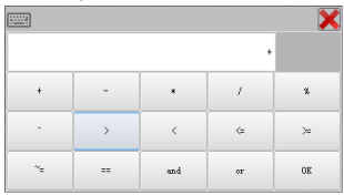
Introduction to operators:
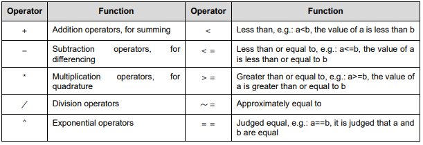

Delete: Choose a new operator or subsequent variables, and then click "Delete" to delete the new operator and subsequent variables.
()-: Adds the () operator.
()-: Deletes the added () operator.
Note
When make replacement, you can select "mathematical function" or "character function". The functions are detailed in xx.
For all operations, you need to move the cursor to the parameter to be modified before performing the command edit operation.
/*…*/ - COMMENT command
COMMENT command, to add definitions or remarks to the program.
This command will not affect the operation of the program, but only for reading and understanding the program.
6.3 WAIT commands
List of WAIT commands is shown in Figure 6-32.
Figure 6-32 List of WAIT commands
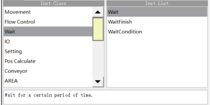
Wait – Delay WAIT commands
It is used to set the robot wait time in ms, either as an int constant or as an INT variable. If you set the wait time to 1s, the two ways to generate the command are:

WaitFinish – Command to wait for a motion segment execution percentage
It is used to control the execution of the program during the robot's motion, and can be set to execute the next line of command when a certain percentage of the motion is executed.
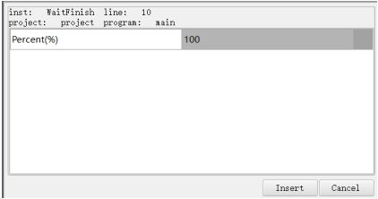
As shown in the example, the SetDO command will trigger when the first MovL command reaches 20%.
The second MovL command will be execute after the first MovL command execution is finished.
If WaitFinish (20) is deleted, SerDO will be executed after the first MovL command is executed, followed by the second MovL command. In this case, there is no transition but hold between the two MovL commands.

WaitCondition – Command to wait to specify a judgement condition
Set the conditions for the robot to execute the WAIT. If the condition is satisfied, the next command is executed. If the condition is not satisfied within the set time, it returns to the timeout state and continues with the next command.
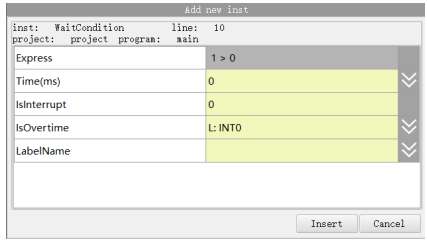
Execute the next command only when the "judgement condition" is TRUE, otherwise the program will continue to wait until the expression becomes TRUE.
"Duration" refers to the time required to execute the WAIT, and may be of type int constant or INT variable, in ms.
− If the value of this parameter is 0, the next command can only be executed when the condition for judgment condition is TRUE.
− If the value of this parameter is not 0, even if the condition for judgment is still not TRUE, the system will skip the command after waiting for a given period of time and continue to execute the next command.
Interrupt enabling: Set whether or not to continue timing after the program resumes during the waiting process.
− 0: Stop timing when the program stops, and continue timing before the program stopped when being resumed.
− 1: When the program stops, stop timing, and continue timing when being resumed.
Timeout judgment value: Choose a variable and assign a value to it in the following two cases.
− If the input condition is TRUE and the command is executed, assign a value of 0 to the variable;
− When the command is executed due to timeout, assign 1 to the variable.
Tag name for timeout jump: When the execution timed out, choose the line where the tag name is located.

6.4 IO commands
The list of IO commands are shown in Figure 6-33.
Figure 6-33 List of IO commands
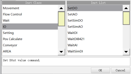
For these commands, the digital and analog signals of the input and output modules will be used. The digital and analog signals are often used in conjunction with trigger information.
SetDO - Set digital output command
Set the digital output port to TRUE (1) or FALSE (0),
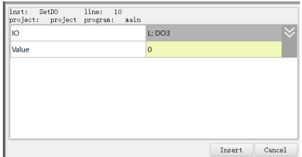
Port Variable: The digital output port to be set
Port Value: The value of the digital output port to be set, either 0 or 1 can be entered, representing the low or high level of the port respectively.
For example:

SetAO - Set analog output command
Set the analog output port to a certain value,
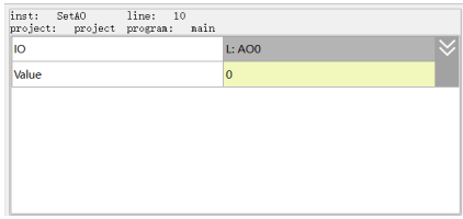
For example:

SetSimDO - Set virtual digital output port command
Set the virtual digital output port to TRUE (1) or FALSE (0).
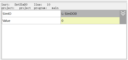
For example:
SetSimAO - Set virtual analog output port value
Set the virtual analog output port to a certain value.
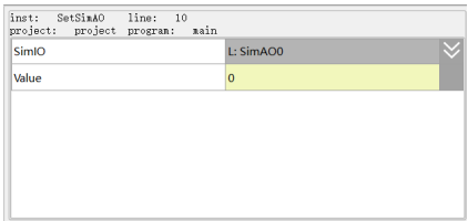
For example:

WaitDI - Command to wait for a digital input
Wait until the digital input port has been set or reset.
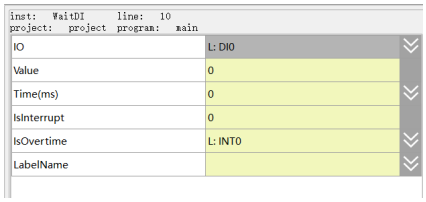
Port variable: The number of the input port to be waited for.
Port value: The digital input port level to be waited for.
− 0: Low level
− 1: High level
Duration (ms): The time to wait for signal change, either of type int constant or INT variable.
Interrupt enabling: Whether or not to continue timing after the program resumes during the waiting process.
− 0: Stop timing when the program stops, and continue timing before the program stopped when being resumed.
− 1: When the program stops, stop timing, and continue timing when being resumed.
Timeout judgment value: Return to the state after the command is executed
− 0: Signal is detected successfully
− 1: No signal is detected, and the command times out and returns.
Tag name for timeout jump: When the execution timed out, choose the line where the tag name is located.
Example

WaitDI8421 - Command to wait for a group of digital inputs
This command is used to wait for the state combination of a group of continuous digital input DI port within the specified time. If the condition for waiting is met within the set time, the program continues to execute downward; if not, the timeout judgment value is set to 1, and the program continues to execute downward.
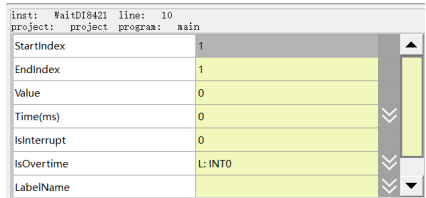
Duration: The time spent in waiting for the DI signal of this group of digital inputs, either of type int constant or INT variable, in ms.
Interrupt enabling: The parameter is used to set whether or not to restart timing after restarting if the program is halted when waiting.
− 0: When the program is halted, timing is stopped but continued from the time before the program pause when resuming the operation.
− 1: When the program is halted, timing is stopped but restarted when resuming the operation
Start DI port: The start port number of the continuous DI port in this segment.
End DI port: The end port number of the continuous DI port in this segment.
Start port 8421 value: Convert the continuous DI port value of this segment into a decimal number. If it is equal to the VALUE, it will then be deemed to satisfy the condition.
Timeout judgment value: Return to the state after the command is executed.
− 0: Signal is detected successfully
− 1: No signal is detected, and the command times out and returns.
Tag name for timeout jump: When the execution timed out, choose the line where the tag name is located.

WaitAI - Command to wait for analog input
Wait until the analog input port value is equal to the given one. The parameter specifications are the same as that of WaitDI.
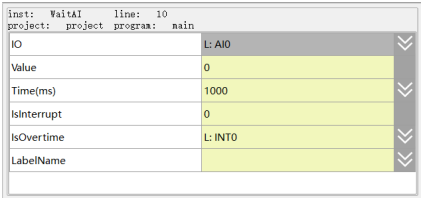
Example

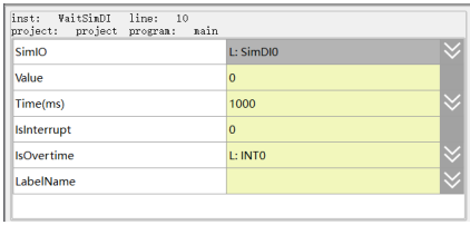
WaitSimDI - Wait until the virtual digital input signal has been set
Wait until the virtual digital input port is set or reset. The parameter specifications are the same as that of WaitDI.

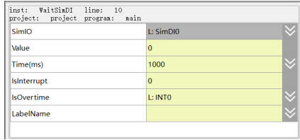
WaitSimDI - Wait until the virtual digital input signal has been set
Wait until the virtual digital input port is set or reset. The parameter specifications are the same as that of WaitDI.

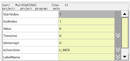
WaitSimDI8421 - Command to wait for a group of virtual digital inputs
Wait for the state combination of a group of continuous virtual digital input SimDI ports within the specified time. The parameter specifications are the same as that of WaitDI8421.
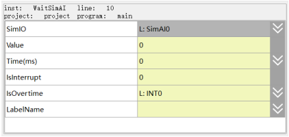
WaitSimAI - Command to wait for virtual analog input
Wait until the virtual analog input port value is equal to the given one. The parameter specifications are the same as that of WaitAI.

PulseOut - Set pulse output command
Set the pulse time and conditions of IO variable output.
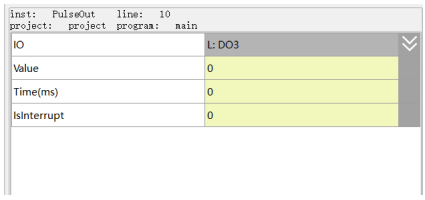
Port variable: The port number to be set.
Port value: Set the output pulse level.
− 0: Low level
− 1: High level
Duration: Set the time of pulse output.
Interrupt enabling: Whether the pulse output will continue to be output or not upon interruption.
− 0: When the program is stopped, the pulse output will continue for the set time and then stop. Its function will not be affected by the program stopping.
− 1: When both the program and output are stopped, the output will continue when the program continues to run, which means that it is synchronized with the program running state. The output acts based on the state of the program

PulseSimOut - Set the pulse time and conditions for the SimIO output signal
Set the pulse time and conditions of SimIO variable output.
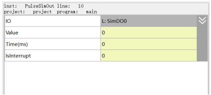
Port variable: The port number to be set.
Port value: Set the output pulse level.
− 0: Low level
− 1: High level
Duration: Set the time of pulse output.
Interrupt enabling: Whether the pulse output will continue or not upon interruption.
− 0: When the program is stopped, the pulse output will continue for the set time and then stop. Its function will not be affected by the program stopping.
− 1: When both the program and output are stopped, the output will continue when the program continues to run, which means that it is synchronized with the program running state. The output acts based on the state of the program.

GetDI8421 - Command to get a segment of continuous digital input values
Acquire a segment of continuous DI port status (regard it as a segment of binary data), and return it as a decimal number.
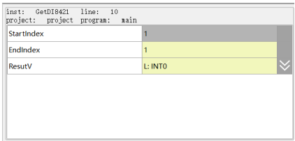
Start DI port: The start DI port number you want to acquire.
End DI port: The end DI port number you want to acquire.
Return value: Store the acquired port state value into the int variable that has been fed.


SetDO8421 –Set a segment of continuous digital output port status
Set a segment of continuous DO port status (regard it as a segment of binary data); convert the decimal number transmitted in into a binary number, and set it to the designated DO port.
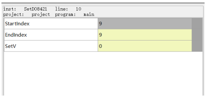
Start DO port: The start DO port number to be set.
End DO port: The end DO port number to be set.
Set value: The decimal value that the port will outputs.
For example, 3 is 0011 when being converted into binary, then Ports 9 and 10 will output high level, respectively. 2 is for Port 9 low level. Set Port 10 to high level.

SetSimDO8421 - Command to set up a continuous virtual digital output
Set a segment of continuous SimDO port state (regard it as a segment of binary data); convert the decimal number transmitted in into a binary number, and set it to the designated SimDO port.
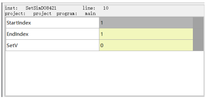
Start DO port: The start SimDO port number you want to acquire.
End DI port: The end SimDO port number you want to acquire.
Set value: The decimal set value that the port will output.

GetSimDIToVar – Report the virtual digital input value to the specified variable
Map the virtual digital input signal to a variable.
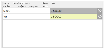
Port variable: The variable used to acquire the value of the virtual digital input signal. It is a virtual digital input variable.
Variable: The variable to which the acquired digital signal value is assigned. It is of type BOOL.
For example, the command that assigns the value of the virtual digital input variable SIMDI1 to BOOL0 can be as follows:

SetSimDOByVar – Map Boolean values to digital output signals
Map the value of a Boolean variable to a digital output variable.
Port variable: The variable of digital output type, which receives the value of the variable and outputs it.
Variable: Boolean type, which outputs its value to port variable.
For example, the command that output the value of BOOL0 to the virtual digital output variable SimDO1 can be as follows:

GetSimAIToVar – Map virtual analogue input signals to variables
Map the virtual analog input signal to a variable.
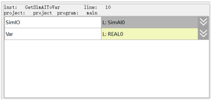
Port variable: The variable used to acquire the value of the virtual analog input signal. It is a virtual analog input variable.
Variable: The variable assigned to the acquired analog signal value. It is REAL type.
For example, the command that assigns the value of the virtual analog input variable SIMAI1 to the real number variable REAL0 can be as follows:

SetSimAOByVar – Command to set the specified variable value to the virtual volume output
Map the value of a REAL variable to a virtual analog output variable.
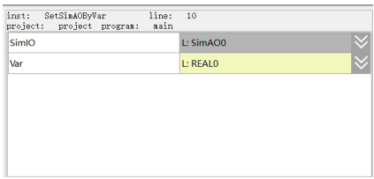
Port variable: The variable of virtual analog output type, which receives the value of the variable and outputs it.
Variable: REAL type, which outputs its value to port variable.
For example, the command that outputs the value of the real number variable REAL0 to the virtual analog output variable SimAO0 can be as follows:

SetDIEdge - Command to set the edge signal state of a digital input variable
Set the edge signal state of a virtual digital input port forcibly by using the commands.
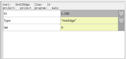
Port variable: The variable of digital input type; it is used to set the rising or falling edge of the port.
Edge type: Choose the edge signal status of the port to be set.
− riseEdge: Status of rising edge.
− downEdge: Status of falling edge.
Edge value: The edge status value to be set.
For example, the command that sets the rising edge status of SimDI1 port to 0 can be as follows:

SetSimDIEdge - Set the edge signal state of a virtual digital input variable
Set the edge signal state of a virtual digital input port forcibly by using the commands.
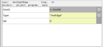
Port variable: The variable of digital input type; it is used to set the rising or falling edge of the port.
Edge type: Choose the edge signal status of the port to be set.
− riseEdge: Status of rising edge.
− downEdge: Status of falling edge.
Edge value: The edge status value to be set.
For example, the command that sets the rising edge status of SimDI1 port to 0 can be as follows:

6.5 SET commands
The list of SET commands is shown in Figure 6-34.
Figure 6-34 List of SET commands
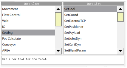
SetTool - Set Tool Parameters command
Select the command of Tool Coordinates. Refer to the description in 4.3.4 Tool Coordinates for the way of tool coordinates settings. For example,

SetCoord - Set User Coordinates command
Select the command of User Coordinates. Refer to the description in 错误!未找到引用源。for the way of user coordinates settings. For example:

SetExternalTCP - Set External TCP Coordinates command
It is used to set the reference coordinates of the system to external tool coordinates. After command execution, the system will switch the reference coordinates to the external tool coordinates. The robot will then move relative to the external tool coordinates. For example:

SetPositioner - Set POSITIONER Coordinates command
It is used to set the reference coordinates of the system to POSITIONER coordinates. After command execution, the system will switch the reference coordinates to the POSITIONER coordinates. The robot will then move relative to the POSITIONER coordinates. For example:

Note
POSITIONER0 is of a positioner variable. The content in "错误!未找到引用源。错误!未找到引用源。 POSITIONER" gives a detailed description.
SetPayload - Set Load Weight command
Select the workpiece load parameter command. For example:

SetJointDyn - Set Joint Motion Parameters command
It is used to set dynamic joint parameters, including Acceleration, Deceleration, Jerk, and Torque. After running the command, the subsequent motion commands will all run using such dynamic parameters.
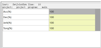
Acceleration: The percentage of the maximum acceleration of the joint.
Deceleration: The percentage of joint maximum deceleration.
Jerk: The percentage of the maximum jerk of the joint.
Torque: The percentage of the maximum torque of the joint.

SetCartDyn - Command to set dynamic parameters for linear or circular motion
Set the dynamic parameters in Cartesian space. After running this command, the subsequent motion commands will run using this dynamic parameter.
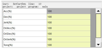
Acceleration: The percentage of the maximum acceleration in linear motion.
Deceleration: The percentage of the maximum deceleration in linear motion.
Jerk: The percentage of the maximum jerk in linear motion.
Posture Acceleration: The percentage of the maximum rotating acceleration of the posture.
Posture Deceleration: The percentage of the maximum rotating deceleration of the posture.
Posture Jerk: The percentage of the maximum rotating jerk of the posture.
Torque: The percentage of the maximum torque of the joint

SetCARAMode - Set SCARA mode instruction
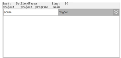
Blend Type
Data type: enum (FINE/RELATIVE/DEFAULT)
Parameter meaning: The transition mode of the robot when approaching the endpoint
− FINE: No transition.
− RELATIVE: Relative transition. The transition parameter is a relative value that represents the percentage of the distance from the transition point to the path endpoint relative to the full length of the path.
− ABSOLUTE: Absolute transition. The transition parameter is an absolute value that represents the distance from the transition point to the endpoint of path. from the transition point to the endpoint of path.
Blend Value
Data type: ZONE
Parameter meaning: The transition value when the robot is approaching the end point.
Note: This parameter can be defaulted and the default value is C100.
For example:

SetOverRide - Set override
Override setting. Set the "Override" to an appropriate percentage value
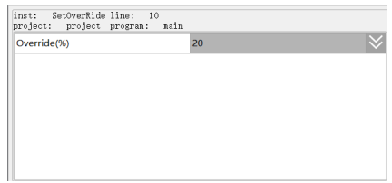
For example:

SetSingularPass - Set Singular Pass command
Set the cross-wrist singular function switch command with the options "OPEN" and "CLOSE". For example:

SetColliEnable - Set Collision Detection Enable command
A command to set the collision detection enable.
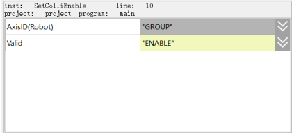
Axis number parameter: "GROUP, A1, A2, A3, A4, A5, A6". When the axis number is "GROUP", all axes are involved;
Enable parameter: "ENABLE, DISABLE"

SetColliEnable - Set Collision Detection Enable command
A command to set the collision detection enable.
Axis number parameter: "GROUP, A1, A2, A3, A4, A5, A6". When the axis number is "GROUP", all axes are involved;
Enable parameter: "ENABLE, DISABLE".

SetAxisColliParam - Set Collision Detection Sensitivity command
A command used to set the collision detection sensitivity value.
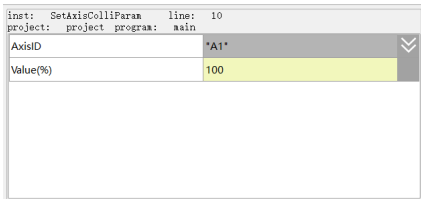
Axis number parameter: " A1, A2, A3, A4, A5, A6";
Sensitivity parameter: in percentage, parameter range [1,500].

GetCurOverRide - Get Current Override command
Get the current override. Get the "Override" as an appropriate percentage value and output it to the int variable.
For example:

Hand - Set Left and Right Hand System
Set the left and right hand system. It is only applicable to SCARA models. Set the parameter value of “Left/Right Hand System” to "Lefty", "Righty" or "Default".
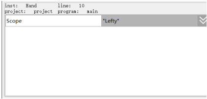
For example:

CalcTool - Calculate tool parameters
It calculates the tool parameters according to the four "calibration points", and saves them to the coordinate system set by the "tool parameters".
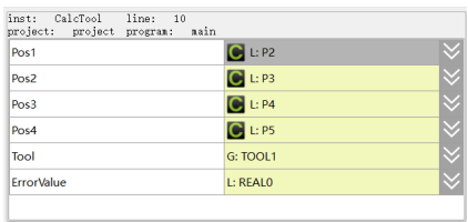
For example:

CalcCoord - Calculate user coordinate parameters
Using this command, you can calculate the user coordinate system parameters according to the set "origin", "RX direction calibration point" and "RXRY plane calibration point", and saves them to the coordinate system set by the "user parameters".
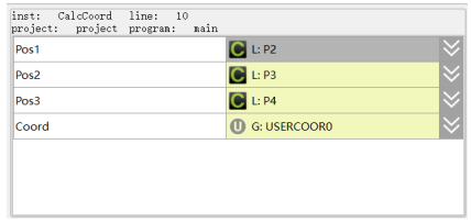
For example:

SetRtToErr - Set Alarm command
Enable the robot to stop running and issue an error message. For example:
Error message: Set the error message, both English and Chinese input are supported.
Error number: Set the error number.
For example:

SetRtInfo - Set prompt messages
Set the prompt message but does not affect the robot operation. For example:
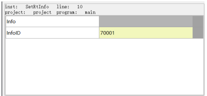
For example:

SetRtWarning - Set alarm messages
Set the warning message but does not affect the robot operation.
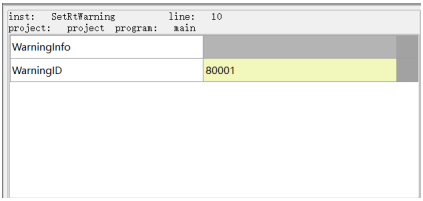
For example:

Stop - Stop Run command
Stop the execution of all the activated programs.

SetMotionMode - Set motion mode
This command can only be created in administrator permission. Set the mode mode.
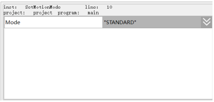
Motion mode: "STANDARD".
"LOW_OSCILLATION" (low oscillation)
For example:

AutoGainEnable – Set Servo Parameter Gain command
The command to enable servo self-adjustment. After executing this command, the system will optimize the subsequent motion commands at low speed according to the incoming LsScale and LsThresh parameters.
For details on how to use this command, please refer to "7.24 Servo parameters self-adjustment".
SetAxisVibraBLevel - Set Vibration Suppression Level command
The command to set the vibration suppression level. It is only valid for input shaping
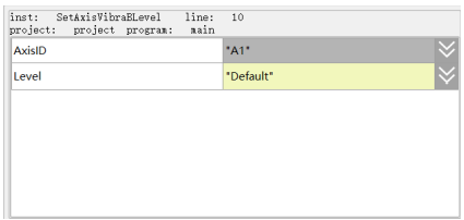
Axis number: The axis number to which the vibration suppression level will be set. (A1/A2/A3/A4/A5/A6)
Level: The level of vibration suppression to be set. (Highest/High/Default/Low/Lowest)
For example:

SetRestorePC - Command to set PC when program resumes
This command sets the pc pointer when the run program goes from Halt/Stop to run. Please note that this command is only valid for use in run programs. The command parameters are detailed as below:
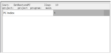
Program pointer: The line number when the run program resumes running.
For example:

SetCircMode - Setting Arc Mode Commands
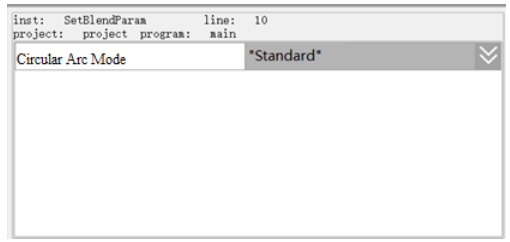
Circular Arc Mode: Turn on or off the circular arc over mid-assist point function, Standard or MidPosePass
- Standard: turn off the function of arc over mid-assist point pose.
- MidPosePass: turn on the function of arc over mid-assist point pose.
Note
This function only supports SCARA models.
SetOriMode – Set Posture Mode command
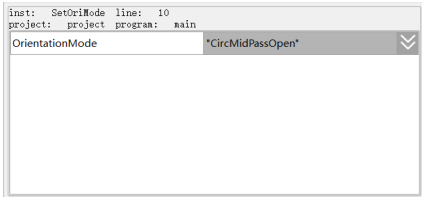
Posture modes: The robot posture interpolation modes. i.e. "Standard", "Teach" and "Shortest".
- Standard: Move to the target point according to the standard mode.
- Teach: Move to the target point according to the actual teaching point.
- Shortest: J4 reaches the target point with the least amount of rotation; if the angle difference is less than or equal to 180°, J4 moves completely to the target point; if the rotation of J4 is greater than 180, the robot moves to the target point in the reverse direction; however, when the reverse movement is beyond the limit range of the robot, it will continue to move in the original direction (e.g., the starting point of J4 is 280°, and the end point of J4 is 40°, at this time, J4 rotates from 280° to 0° via 280° to 40° via 0°).
- Note: This version defaults to Teach mode, while the previous version defaulted to Standard mode. If you upgrade from the old version to this version, the attitude and rotation direction of some motion commands may change, so you should run at low speed first to make sure there is no interference before normal operation.
Note
This function is only available for SCARA models.
GetRobIsMoving – Command to get current robot's motion status
It is used to get the current robot motion status.
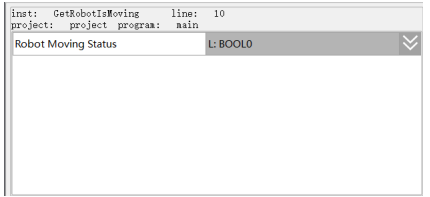
Robot motion status (%): SET commands. By using this command, the user can get whether the robot is currently in motion or not.
SetColliAutoTune – Collision Detection Parameter Self-Adjustment command
It is used to set the self-adjustment of the collision detection parameters.
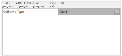
Self-adjustment phase for collision detection parameters:
Start
Pause
Continue
End
Calculate
Note
1. When Start, Pause, Continue, End is selected for the self-adjustment phase of the collision detection parameter, the data recording status of the self-adjustment function will be set.
2. If the parameter of the self-adjustment phase of the collision detection is set to "Calculate", the selfadjustment parameter will be calculated based on the data recorded by the self-adjustment function, the detection method and the sensitivity and the result will be stored in the ID corresponding to the collision parameter, as shown in the figure below:
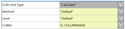
Collision detection parameter self-adjustment phase: Self-adjustment parameter "Calculate".
Detection method: Collision detection method used for self-adjustment
Default
Default+
Default++
[Note]: This parameter is only valid when the parameter is set to Calculate in the self-adjustment phase of the collision detection parameter.
Sensitivity: Sensitivity level of the self-adjustment result
Highest
High
Default
low
lowest
[Note]: This parameter is only valid when it is set to Calculate in the self-adjustment phase of the collision detection parameter.
Collision parameter: The collision parameter that stores the results of the self-adjustment calculation. It is a global variable of type COLLIPARAM, where one variable corresponds to one ID and the self-adjustment result is stored in the ID corresponding to the selected variable.
SetColliParam – Set Collision Parameter command
It is used to set the collision detection parameters.
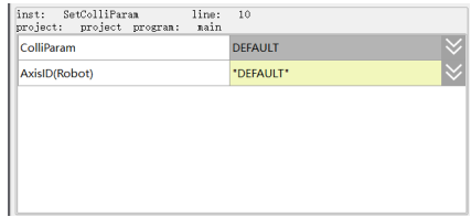
Collision parameter: The parameter used by the collision detection function. When self-adjustment parameters are required, select the variables from the COLLIPARAM type (corresponding to the actual ID to be set), otherwise select DEFAULT (factory default).
Axis number (or group of axes): Select single axis number or all axes (GROUP) when setting the collision detection "validity" or "sensitivity value". By default, DEFAULT is selected.
DEFAULT: default value, meaningless
GROUP: All axes
A1: A1 axis
A2: A2 axis
A3: A3 axis
A4: A4 axis
A5: A5 axis
A6: A6 axis
VALIDITY: Controls the ON and OFF of the collision detection function for the corresponding axis number.
ENABLE (ON)
DISABLE (OFF)
[Note]: This parameter is only valid when the axis number is set to non-DEFAULT.
Sensitivity value (%): Sensitivity value of the collision detection in percentage, parameter range [1,500].
[Note]: This parameter is only valid when the axis number is set to other than DEFAULT.
Note
1. Only the main unit axis of the robot is supported.
2. Setting a stronger detection method and higher sensitivity level would increase the sensitivity of collision detection but may also increase the probability of false alarms.
6.6 POSITION operation commands
The list of POSITION operation commands is shown in Figure 6-35.
Figure 6-35 List of POSITION operation commands
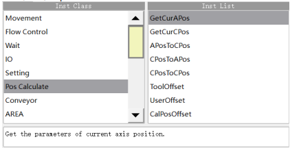
Posture modes: The robot posture interpolation modes. Currently only the "CircMidPassOpen" and "CircMidPassClose" posture modes are supported for circular arcs passing through intermediate auxiliary points;
- CircMidPassOpen: Enables the effect of interpolation of circular arcs passing through intermediate auxiliary points.
- CircMidPassClose: Disables the effect of interpolation of circular arcs passing through intermediate auxiliary points.
GetCurAPos - Get Current Joint Position command
Get the position in the current joint coordinate system, and assign it to the Apos variables.

GetCurCPos - Get Current Cartesian Coordinates Position command
Get the Cartesian space position in the current coordinate system (world coordinates or user coordinates), and assign it to the Cpos variables.
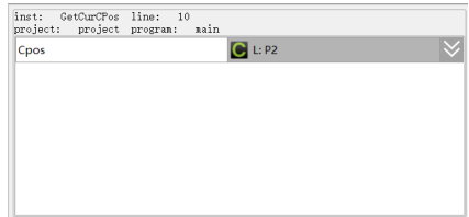

APosToCPos -Robot Position Conversion command (Apos to Cpos)
The command of robot position point conversion, through which APos points can be converted to CPos points.
Being given the APos point, as well as the user coordinates and tool parameters of the target CPos point to be converted, the value of the target CPos point can then be derived.
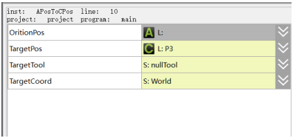
Original position: The joint position before conversion.
Target position: The target Cartesian space position.
Target tool parameters: The target tool parameters
Target coordinates: The reference coordinates

CPosToAPos - Robot Position Conversion command (Cpos to Apos)
The command of robot position point conversion, through which CPos points can be converted to APos points.
Being given the CPos point, as well as the user coordinates and tool parameters of the target APos point to be converted, the value of the target CPos point can then be derived.
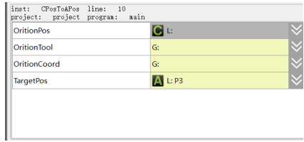
Original position: The Cartesian space position before the conversion.
Original tool parameters: The tool parameters before the conversion.
Original coordinates: The parameters of the reference coordinate system before the conversion.
Target position: The joint position after the conversion.

CPosToCPos - Robot Position Conversion command (Cpos to Cpos)
The command of robot position point conversion, through which CPos points can be converted to CPos points.
Being given the CPos point, as well as the user coordinates and tool parameters of the target CPos point to be converted, the value of the target CPos point can then be derived.

ToolOffset - Tool Coordinates Offset command
The Robot Tool Coordinates Offset command, which rotates or offsets the reference tool coordinates to create the new tool coordinates.
Being given the reference tool coordinates TOOL and the offset to be shifted or rotated, the value of the target tool coordinates can be calculated.

UserOffset - User Coordinates Offset Command
The Robot User Coordinates Offset command, which rotates or offsets the reference user coordinates to create the new user coordinates.
Being given the reference user coordinates USERCOORD and the offset to be shifted or rotated, the value of the target user coordinates can be calculated.

CalPosOffset – Calculate Position Point Offset Result command
The Calculate Position Point Offset Result command. It calculates the position value after the original position has been offset relative to the coordinates or tool, based on the original position amount and the relative offset amount.
This command offsets a position point (APOS or CPOS) relative to the coordinates or tool by the amount of the DCPOS, and finally gets a target position value, which is of type CPOS.
Figure 6-36 CalPosOffset command editing interface
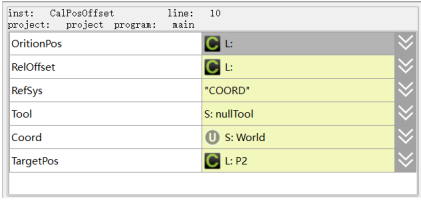
Original position: The start point of the offset motion (APOS or CPOS);
Relative offset: The increment of the position to be moved relative to the original position (DCPOS);
Reference coordinates: The selection of the coordinates offset or tool offset. "Coord" indicates an offset relative to the current user coordinates; "Tool" indicates an offset relative to the tool coordinates, i.e. translation or rotation with reference to Tx, Ty, Tz;
Tool parameters: The information on the tool to which the original position and the target position belong;
Coordinate parameters: The information on the coordinates to which the original and target positions belong;
Target position: The final position after offset (CPOS).
6.7 Conveyor tracking commands
The list of conveyor tracking commands is shown in Figure 6-37.
Figure 6-37 List of conveyor tracking commands
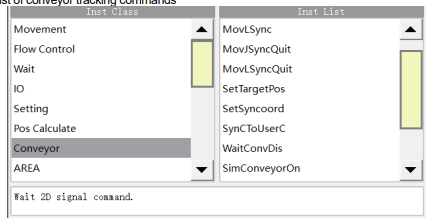
WaitWObj - Waiting for Visual Information Input command
This is the command of waiting for the visual information, to wait for the workpiece position information sent from the vision.
Figure 6-38 Parameter editing interface of WaitWObj
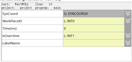
Moving coordinate system: SYNCOORD variable. The set moving coordinate system needs to be consistent with the moving coordinate system enabled on the conveyor configuration interface.
Workpiece id: Variable of type INT, which returns the id of the currently received workpiece.
Duration: Indicates the time required to execute waiting, in ms.
− If the value of the parameter is 0, it will be forced to wait until it receives the workpiece position information data from the vision before proceeding the next command.
− If the value of the parameter is not 0, even if no data is received, the system will skip the command after waiting for a given period of time, and proceed the next command.
Timeout judgment value: Select a variable and assign a value to it in the following two cases.
− When the command is executed within the waiting time, assign 0 to the variable;
− When the command is executed due to timeout, assign 1 to the variable.
Tag name for timeout jump: When the execution timed out, choose the line where the tag name is located.
For example:

MovLSync – Command to initiate linear motion for conveyor synching
The command to initiate linear motion for conveyor synching, through which the TCP point of the robot can track the conveyor at the set speed, and reach the target position in a linear motion.
Figure 6-39 Parameter editing interface of MovLSync
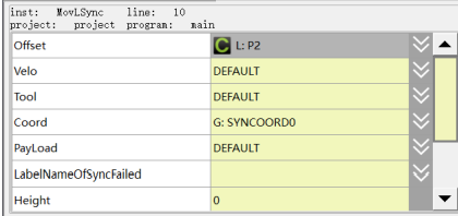
Before this command is executed, the robot control system will trigger the vision to shoot through IO and receive the target position from the vision system. When the command is executed, the robot will move from the current to the target position and keep in sync with the moving target object.
Target position offset: The offset relative to the tracked target object, it can only be set as a CPOS position point.
Choose an existing point from the drop-down list.
Target speed: The running speed of command.
− When setting it to “DEFAULT”, the default value V4000 will be used.
− When it is set to SPEED variable, you can selected the system pre-defined one, or create it by yourself.
Tool Parameters: The tool parameters used when the robot executes the path.
− When setting it to “DEFAULT”, the tool parameters set last time will be continuously used.
Coordinate System Parameters: The coordinate system parameters used by the robot when executing the path.
Only the variable of SYNCOORD type can be set, but needs to be consistent with the moving coordinate system on the conveyor configuration interface.
Workpiece load: The workpiece load parameter used by the robot when executing the path.
− It is set to “DEFAULT”, which means to continue to use the workpiece load parameters set last time.
− When it is set to PAYLOAD variable, you can selected the system pre-defined one, or create it by yourself; when a load parameter different from the current workpiece load parameter is used, the system will switch the workpiece load parameter to the set parameter. If the tool parameters of the path of current segment and the preceding/next segments change, the transition will not be supported.
Jump label when aborting during synchronization: It is used to follow the Aborting function. When the robot fails to synchronize with the target workpiece during synchronization, i.e. when the execution of the MovLSync command fails, the program pointer will go to the line where the Jump label is located to perform the Aborting operation. The user can add the corresponding command under this Label according to the working conditions on site.
− This value can be set by default. When set to default, it will jump to the Label used for the "Jump to label when aborting after synchronization".
Lift height when aborting after sync: The distance lifted while following when aborting after sync, this is the offset relative to the positive direction of the Z axis of the moving coordinates.
Jump label when aborting following sync: It is used to follow the Aborting function. When the robot cannot continue following during the following motion, i.e. the execution of the subsequent commands of the MovLSync command fails, the program pointer will go to the line where the jump label is located to perform the Aborting operation.
− This value cannot be defaulted and requires special attention in this case.
AddDo: Robot will perform IO operation after executing this command.
− NULL: No operations.
− IO commands: Perform IO operations, the IO commands currently supported are SetDo, SetAo, SetSimDo, SetSimAo, PulseOut, PulseSimOut, SetDO8421, SetSimDO8421, SetDIEdge and SetSimDIEdge.
MovJSyncQuit - Sync Follow Quit command
This is the command of conveyor syn tracking, through which the TCP point of the robot can quit the conveyor tracking status at the set speed and reach the target position in the fastest mode.
Figure 6-40 Parameter editing interface of MovJSyncQuit
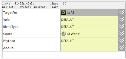
When executing this command, the robot transits smoothly from the previous motion command and quits the tracking status, and then resumes the motion in the normal user coordinates.
Target position: the endpoint position of the command (the position point of APOS or CPOS).
− Select an existing point from the drop-down list, or create a new a variable in the pop-up dialog box for teaching.
Target speed: The running speed of command.
− When setting it to “DEFAULT”, the default value V4000 will be used.
− When it is set to SPEED variable, you can select the system pre-defined one, or create it by yourself.
Transition type: The way of transition when the robot approaches the endpoint.
− DEFAULT: Default, i.e. no transition parameter is set in the command. If the SetBlendParam parameter is used in the program, the transition mode operates as per the globally set transition parameter.
− FINE: Equivalent in effect to DEFAULT.
− RELATIVE: Relative transition. The transition parameter is a relative value that represents the percentage of the distance from the transition point to the path endpoint relative to the full length of the path.
− ABSOLUTE: Absolute transition. The transition parameter is an absolute value that represents the distance from the transition point to the endpoint of path. from the transition point to the endpoint of path.
Coordinate System Parameters: The coordinate system parameters used by the robot when executing the path.
− This parameter cannot be set to “DEFAULT” and must be forced to enter a coordinate system parameter.
− When it is set to USERCOOR variable, you can select the system pre-defined one, or create it by yourself. When a coordinate system different from the current one is used, the system will switch the coordinate system to the set one.
Workpiece load: The workpiece load parameter used by the robot when executing the path.
− It is set to “DEFAULT”, which means to continue to use the workpiece load parameters set last time.
− When it is set to PAYLOAD variable, you can select the system pre-defined one, or create it by yourself; when a load parameter different from the current workpiece load parameter is used, the system will switch the workpiece load parameter to the set parameter. If the tool parameters of the path of current segment and the preceding/next segments change, the transition will not be supported.
AddDo: Robot will perform IO operation after executing this command.
− NULL: No operation.
− IO commands: Executing IO operation. The IO commands currently available are SetDo, SetAo, SetSimDo, SetSimAo, PulseOut, PulseSimOut, SetDO8421, SetSimDO8421, SetDIEdge, and SetSimDIEdge.
MovLSyncQuit - Sync Follow Quit command
This is the command of conveyor syn tracking QUIT, through which the TCP point of the robot can quit the conveyor tracking status at the set speed and reach the target position by linear motion.
Figure 6-41 Parameter editing interface of MovLSyncQuit
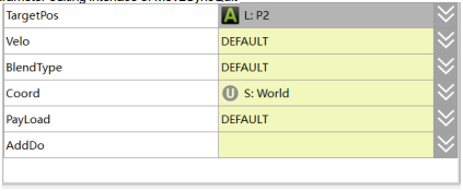
When executing this command, the robot transits smoothly from the previous motion command and quits the tracking status, and then resumes the motion in the normal user coordinates.
Target position: the final position of the command (the position point of APOS or CPOS).
− Select an existing point from the drop-down list, or create a new a variable in the pop-up dialog box for teaching.
Target speed: The running speed of command.
− When setting it to “DEFAULT”, the default value V4000 will be used.
− When it is set to SPEED variable, you can select the system pre-defined one, or create it by yourself.
Transition type: The way of transition when the robot approaches the endpoint.
− DEFAULT: Default, i.e. no transition parameter is set in the command. If the SetBlendParam parameter is used in the program, the transition mode operates as per the globally set transition parameter.
− FINE: Equivalent in effect to DEFAULT.
− RELATIVE: Relative transition. The transition parameter is a relative value that represents the percentage of the distance from the transition point to the path endpoint relative to the full length of the path.
− ABSOLUTE: Absolute transition. The transition parameter is an absolute value that represents the distance from the transition point to the endpoint of path. from the transition point to the endpoint of path.
Coordinate System Parameters: The coordinate system parameters used by the robot when executing the path.
− This parameter cannot be set to “DEFAULT” and must be forced to enter a coordinate system parameter.
− When it is set to USERCOOR variable, you can select the system pre-defined one, or create it by yourself. When a coordinate system different from the current one is used, the system will switch the coordinate system to the set one.
Workpiece load: The workpiece load parameter used by the robot when executing the path.
− It is set to “DEFAULT”, which means to continue to use the workpiece load parameters set last time.
− When it is set to PAYLOAD variable, you can select the system pre-defined one, or create it by yourself; when a load parameter different from the current workpiece load parameter is used, the system will switch the workpiece load parameter to the set parameter. If the tool parameters of the path of current segment and the preceding/next segments change, the transition will not be supported.
AddDo: Robot will perform IO operation after executing this command.
− NULL: No operation.
IO commands: Executing IO operation. The IO commands currently available are SetDo, SetAo, SetSimDo, SetSimAo, PulseOut, PulseSimOut, SetDO8421, SetSimDO8421, SetDIEdge, and SetSimDIEdge.
SetTargetPos - Set Workpiece Position Info command
This is the workpiece position information setting command. Use it to set the detected position information of the workpiece after entering the conveyor.
Figure 6-42 Parameter editing interface of SetTargetPos
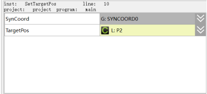
Moving coordinate system: SYNCOORD variable. The set moving coordinate system needs to be consistent with the moving coordinate system enabled on the conveyor configuration interface.
Target position: The CPOS type variable, and also the detected position information of the workpiece after entering the conveyor. Please note that only 2D visual data is currently supported, which means that only X, Y and A are valid in this CPOS type variable.
SetSyncoord - Set Moving Coordinates command
The moving coordinate system set commands. It is used to set the current robot reference coordinates to moving coordinates. This command enables the current robot reference coordinates to be switched to a moving coordinate system, which can quickly teach the posture of the point position during the following process.
Figure 6-43 SetSyncoord parameter editing interface
Coordinate system parameters: The parameters of the coordinate system to which the robot is currently referenced, which can only be set to variables of SYNCOORD.
Note that after switching to a moving coordinate system, only the JOG coordinates set before the switch can be toggled, e.g. if the JOG coordinate system set before the switch is a WORLD coordinate system, then only the WORLD coordinate system can be toggled after the command is executed and cannot be switched.
SynCToUserC - Teach Reference Coordinates Conversion command
The teach reference coordinates conversion command. It is used to solve the coordinate system referenced when following the path point after synchronisation.
Figure 6-44 SynCToUserC parameter editing interface
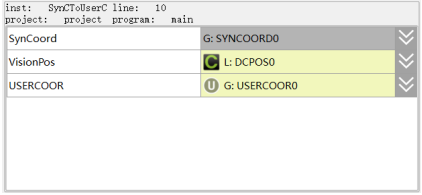
Moving coordinate system: The variable of type SYNCOORD. The moving coordinate system must be the same as the one enabled in the conveyor configuration interface.
Target position: The variable of type DCPOS, indicating the offset of the position of the workpiece entering the conveyor relative to the origin of the moving coordinate system.
Coordinate system parameter: The variable of type USERCOORD, indicating the coordinate system to be referred to when teaching the path point position after synchronization.
WaitConvDis - Waiting for Fixed Increment command
It is used to enable the robot to move in the positive direction of the conveyor in synchronization with the conveyor up to a certain increment before executing subsequent commands, thus allowing the robot to delay the movement for a specified increment. Unlike the Wait commands, this command requires a fixed increment while the Wait command requires a fixed time.
Figure 6-45 WaitConvDis parameter editing interface
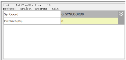
Moving coordinate system: The variable of type SYNCOORD. The moving coordinate system must be the same as the one enabled in the conveyor configuration interface.
WAIT increment: The value of the increment in which the robot is to be synchronized. In mm for straight conveyors and in deg for disc conveyors.
SimConveyorOn - Virtual Conevyor ON command
The Virtual Conveyor ON command. It is used to enable the virtual conveyor and specify its running speed.
The parameter editing interface of this command is shown in Figure 6-46.
Figure 6-46 SimConveyorOn parameter editing interface
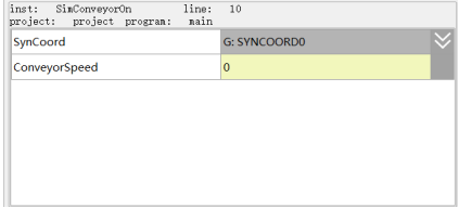
Moving coordinate system: The variable of type SYNCOORD. The moving coordinate system must be the same as the one enabled in the conveyor configuration interface.
Conveyor speed: The speed at which the virtual conveyor runs, in mm/s for linear conveyors and in deg/s for disc conveyors.
SimConveyorOff- Virtual Conveyor OFF command
The Virtual Conveyor OFF command. It is used to disable the virtual conveyor. The parameter editing screen of this command is shown in Figure 6-47.
Figure 6-47 SimConveyorOff parameter editing interface
Moving coordinate system: The variable of type SYNCOORD. The moving coordinate system must be the same as the one enabled in the conveyor configuration interface.
ReceiveWObj- Workpiece Data Receipt Status command
A command to set the receive status of workpiece data. This command can be used in combination to allow the robot system to not receive workpiece position information from vision or run programs within a certain segment of the path. The parameter editing interface for this command is shown in Figure 6-48.
Figure 6-48 ReceiveWObj parameter editing interface
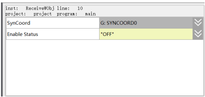
Moving coordinate system: The variable of type SYNCOORD. The moving coordinate system must be the same as the one enabled in the conveyor configuration interface.
Enable receive status: Enables the robot system to receive information on the position of the workpiece.
ResetWObjBuf - Reset Received Workpiece Data Queue command
A command to reset the queue of received workpiece data. It empties the queue of received and unexecuted workpiece information. The parameter editing screen of this command is shown in Figure 6- 49.
Figure 6-49 ResetWObjBuf parameter editing interface
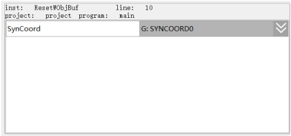
Moving coordinate system: The variable of type SYNCOORD. The moving coordinate system must be the same as the one enabled in the conveyor configuration interface.
6.8 INTERRUPT commands
The list of INTERRUPT commands is shown in Figure 6-50.
Figure 6-50 List of INTERRUPT commands
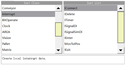
IConnect – INTERRUPT Connection command
The interrupt connection command. It binds the INTERRUPT identifier to the interrupt handler for
operation.
The command binds the INTERRUPT index to the interrupt program. When the signal bound to this index is triggered, the system can execute the INTERRUPT program bound to this INTERRUPT index.
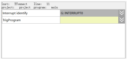
Interrupt identifier: The INTERRUPT index number (INTERRUPT type).
Interrupt handler: The handler to be called when the signal corresponding to this INTERRUPT index is satisfied.
Note
After the INTERRUPT identifier in IConnect is bound to the interrupt program, the IDelete instruction must be executed to delete the identifier variable before IConnect can be re-executed, otherwise an error message will be reported.
When an interrupt identifier variable is created, the value in that variable should be synchronized with the name of that variable. That is, if a new inter1 variable of type INTERRUPT is created, its value should also appear as inter1 when viewed in the variables interface.
The interrupt handler can only be used for programs under this project, no global programs are supported
IDelete – INTERRUPT Release command
The INTERRUPT release command, which removes the connection between the INTERRUPT identifier and the corresponding INTERRUPT handler.
This command removes any data in the system bound to this INTERRUPT index, that is, it removes the detection of this INTERRUPT index and the data in the execution queue.
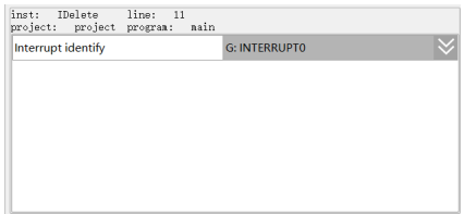
INTERRUPT ID: The INTERRUPT index number (INTERRUPT type).
ITimer – Timer INTERRUPT command
The timer INTERRUPT command. It sets the detection of the INTERRUPT index to be triggered at regular intervals, whereby the corresponding interrupt program of the robot is processed at regular intervals. With this command, the system is allowed to execute the INTERRUPT program periodically according to the set delay time.
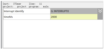
INTERRUPT ID: The INTERRUPT index number (INTERRUPT type).
Trigger time: The timing detection time in ms. Range: 100ms~30,000ms
IsignalDI – Input Port INTERRUPT command
The Input Port INTERRUPT command. It sets the INTERRUPT index detection method to DI edge triggering, that is, it monitors the rising/falling edge signal of DI in real time to process the corresponding INTERRUPT program of the robot.
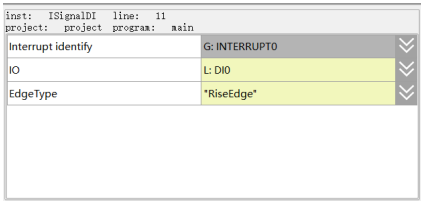
Monitor the active state of the edge signal of the set DI to allow the system to execute the INTERRUPT program with the following command parameters:
INTERRUPT ID: The INTERRUPT index number (INTERRUPT type).
Port variable: The DI port number to be monitored (DI type).
Trigger edge type: The type of DI edge signal to be monitored.
- RiseEdge: The rising edge signal
- DownEdge: The falling edge signal
Note
The INTERRUPT index number in this command must already be bound to the INTERRUPT program, i.e. the IConnect command is executed, otherwise an error message will appear.
After the command has been executed, the corresponding DI valid edge signal is given in the running state of the program and the INTERRUPT program bound to this INTERRUPT index should be executed correctly.
ISignalSimDI – Virtual Input Port INTERRUPT command
The virtual input port INTERRUPT command. It sets the detection of the INTERRUPT index to SimDI edge triggering, i.e. the rising/falling edge signals of SimDI are monitored in real time to process the corresponding INTERRUPT program of the robot.
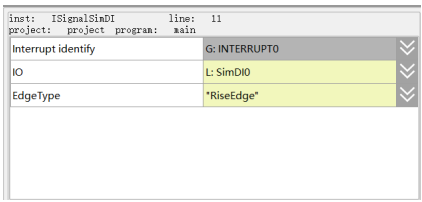
INTERRUPT ID: The INTERRUPT index number (INTERRUPT type).
Port variable: The virtual SimDI port number (SimDI type) to be monitored.
Trigger edge type: The type of SimDI edge signal to be monitored:
- RiseEdge: The rising edge signal
- DownEdge: The falling edge signal
IEnter – Interrupt Current Parsing & Motion command
The command that interrupts the current parsing and motion, stops the parsing and motion of the main program and switches to the INTERRUPT program.
The execution of this command in the INTERRUPT program will stop the main program from parsing and interrupt the current motion; also, it displays the data and program from the INTERRUPT program on the program editing and the variables interfaces.
Note
This command can only be executed in the INTERRUPT program.
MovToIPos – Return Interrupt Point command
The command to return the interrupt point, which moves the robot from its current position to the position point at the moment when the main program was interrupted while it was running.
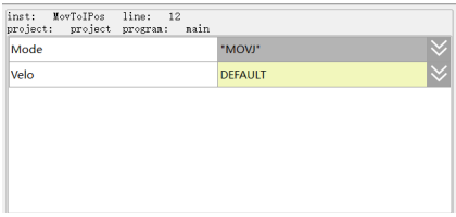
This command specifies the form of motion to bring the robot back to the position at which the main program was interrupted. The system automatically caches the interrupt position when the interrupt occurs, and the command will automatically retrieve the interrupt position from memory and run to that point when it is executed, eliminating the need for additional command processing by the user.
Motion mode: The mode of motion to the interrupt point
MOVJ: Return to the target point as a joint motion
MOVL: Return to the target point as a linear motion
Target speed: The speed of motion to the interrupt point (SPEED type)
IExit – Command to resume pre-interrupt parsing and motion
The command to resume parsing and motion, which cuts the INTERRUPT program to background for execution and resumes parsing and motion of the main program.
After executing this command in the interrupt program, the system will switch the INTERRUPT program to background for execution and put the main program out of sleep, to continue the previous commanded parsing and motion operation, while to display the data and program in the main program on the program editing and the variable interfaces.
ExitCycle – Exit Cycle command
The exit cycle command.
When this command is executed, the system will immediately end the current INTERRUPT program, return the PC pointer to the start of the main program, and restarts execution from that location..
Note
1. This command must be used in conjunction with the IEnter command in the INTERRUPT program.
2. When this command is executed, the system will jump to the "CycleLable" label command if it is taught by the main program, or to the first line of the program being loaded if it is not taught.
6.9 Bit operation commands
The list of bit operation commands is shown in Figure 6-51.
Figure 6-51 List of bit operation commands
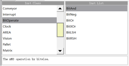
BitAnd - AND operation command
This is the command for bitwise AND operation. It performs bitwise AND operation on two operands, and assigns the result to the first operand.
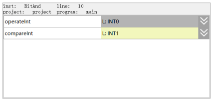
Data to be manipulated: INT variable; the result of the operation is also assigned to this operand.
Data to be compared: INT variable.

BitNeg - Negation operation command
This is the command for bitwise negation operation. It performs bitwise negated operation for the operand, and assigns the result to the operand.
Moreover, only the last 16 bits of the operand are negated.
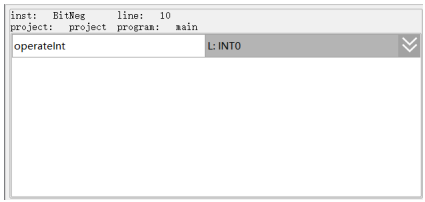
Data to be manipulated: INT variable; the result of the operation is also assigned to this operand.

BitOr – OR operation command
This is the command for bitwise OR operation. It performs bitwise OR of two operands, and assigns the result to the first operand.
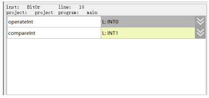
Data to be manipulated: INT variable; the result of the operation is also assigned to this operand.
Data to be compared: INT variable.

BitXOr – XOr operation command
This is the command for bitwise XOr operation. It performs a bitwise XOr operation on two operands, and assigns the result to the first operand.
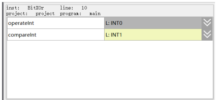
Data to be manipulated: INT variable; the result of the operation is also assigned to this operand.
Data to be compared: INT variable.

BitLSH – Left Shift Bit Operation commands
This is the command for bitwise left shift. It performs bitwise left shift operation of the first operand as per the left shift number specified by the second operand, and assigns the result to the first.
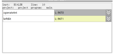
Data to be manipulated: INT variable; the result of the operation is also assigned to this operand.
Bits shifted left: INT variable, the number of bits shifted left.

BitRSH - Right Shift Bit operation commands
This is the command for bitwise right shift. It performs bitwise right shift operation of the first operand as per the right shift number specified by the second operand, and assigns the result to the first.
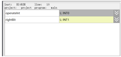
Data to be manipulated: INT variable; the result of the operation is also assigned to this operand.
Data to be shifted right wei2: INT variable, the number of bits shifted right.

6.10 CLOCK commands
The list of CLOCK commands is shown in Figure 6-52.
Figure 6-52 List of CLOCK commands
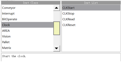
CLKStart - StartCLOCK command
Start the specified clock (after starting, you can view from the variable list that the state of the specified CLOCK variable is TRUE). For example:

CLKStop – Stop CLOCK command
Stop the specified clock (its state is false, but will not be reset). For example:

CLKRead – Read CLOCK command
Read the value of the specified clock, by checking the value corresponding to the variable in the list of variables. For example:

CLKReset – Reset CLOCK command
Reset the state value of the specified clock. For example:

6.11 AREA commands
The list of AREA commands is shown in Figure 6-53.
Figure 6-53 List of AREA commands
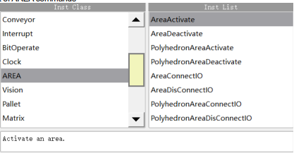
AreaActivate – Activate Standard AREA command
Activate the standard AREA command to make the specified standard area be valid.
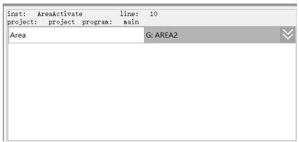

AreaDeactivate – Deactivate Standard AREA command
This is the command for deactivating standard AREA commands to invalidate the specified standard area.

PolyhedronAreaActivate – Activate Polyhedron AREA command
Activate the polyhedron AREA command to enable the specified polyhedron area.

PolyhedronAreaDeactivate - Deactivate Polyhedron AREA command
Deactivate the polyhedron AREA command to disable the specified polyhedron area.

AreaConnectIO – Bind AREA IO command
The command to bind an AREA IO, by which an input port can be bound to the selected area and specify a high and low active level for controlling the start and stop of the robot.
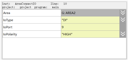
AREA variable: AREA, the standard area variable to be bound.
IO type: The type of IO port to be bound.
- DI: Actual DI.
- SIMDI: Virtual DI.
IO port number: The IO port number to be bound.
IO polarity: The IO polarity to be bound.
− HIGH: Valid at high level.
− LOW: Valid at low level.
AreaDisConnectIO – Unbind area IO command
The command to unbind the area IO, by which the binding to the selected area input port can be removed.
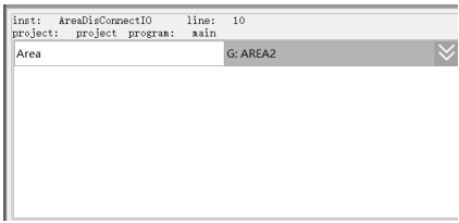
AREA variable: The standard area variable that needs to be unbound.
PolyhedronAreaConnectIO – Bind polyhedron IO command
The command to bind an area IO, by which an input port can be bound to the selected area and a high and low active level can be specified for controlling the start and stop of the robot.
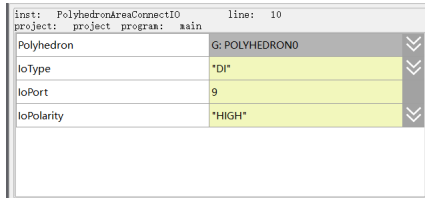
AREA variable: POLYHEDRON, the polyhedron area variable to be bound.
IO type: Type of IO port to be bound.
- DI: Actual DI.
- SIMDI: Virtual DI.
IO port number: The IO port number to be bound.
IO polarity: The IO polarity to be bound.
− HIGH: Valid at high level.
− LOW: Valid at low level.
PolyhedronAreaDisConnectIO - Unbind polyhedron area IO command
Unbind area IO command, by which the binding to the selected area input port can be removed.
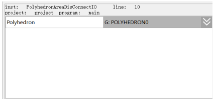
AREA variable: The polyhedron AREA variable to be unbound
6.12 Visual commands
The list of visual commands is shown in Figure 6-54.
Figure 6-54 List of visual commands
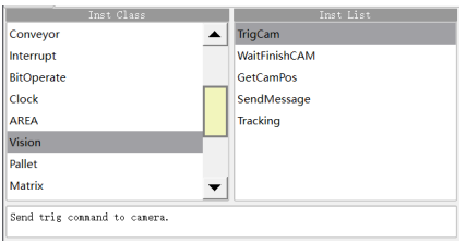
TrigCam – Trigger Camera command
This is the command to trigger the camera shooting.
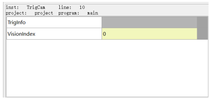

WaitFinishCAM - Wait for Camera Shooting Finish command
This is the command for waiting for the camera to finish shooting

GetCamPos - Get Camera Position command
This is the command for getting the cameral position.
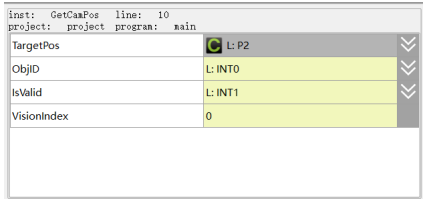

SendMessage - Send String Message command
Send a string message, which can be used for 3D visual commands. It sends the specified string to the camera, and enables the camera to shoot. For example:

Tracking - Conveyor Tracking command
Conveyor tracking command. For detailed description of this command, please refer to the Introduction to parameters in 7.5 Conveyor Tracking.Parameter Description
Enable Checkbox: The switch controlling the Vibration Suppression function ON/OFF.
Checked: Enable the Vibration Suppression function.
Unchecked: Disable the Vibration Suppression function.
Values for Axis 1 to Axis 6: Set the strength of vibration suppression.
Default Value: Standard.
Value Range: There are five levels: Low, Low-Medium, Standard, Medium-High, and High. The vibration suppression effect increases progressively with each level.
Conveyor trackingConveyor tracking

6.13 Palletizing commands
The list of palletizing commands is shown in Figure 6-55.
Figure 6-55 List of palletizing commands
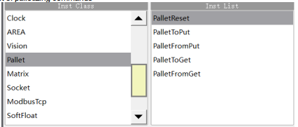
PalletReset - Palletizing Reset command
This is the command for palletizing reset. When a pallet is forced to stop before the palletizing is completed, call this command to restore it.
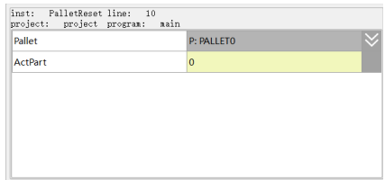
Palletizing name: PALLET variable of the current palletizing.
Number of workpieces: The number of workpieces that have been placed on the current pallet. It must be set from 0 to the maximum number of workpieces of the pallet.

For example, Pallet0 with a maximum number of workpieces of 60 will halt when 8 workpieces have been placed. Call "PalletReset (Pallet0, 8);" to restart the palletizing of subsequent workpieces.
PalletToPut - Put Workpiece command
This is the command for putting workpieces.
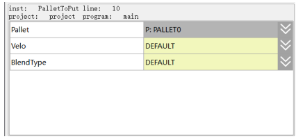
Palletizing name: The PALLET variable of the current palletizing.
Target speed: The running speed of command.
− When setting it to “DEFAULT”, the default value V4000 will be used.
− When it is set to SPEED variable, you can select the system pre-defined one, or create it by yourself.
Transition type: The way of transition when the robot approaches the endpoint.
− DEFAULT: Default, i.e. no transition parameter is set in the command. If the SetBlendParam parameter is used in the program, the transition operates according to the globally set transition parameter.
− FINE: Equivalent in effect to DEFAULT.
− RELATIVE: Relative transition. The transition parameter is a relative value that represents the percentage of the distance from the transition point to the path endpoint relative to the full length of the path.
− ABSOLUTE: Absolute transition. The transition parameter is an absolute value that represents the distance from the transition point to the endpoint of path. from the transition point to the endpoint of path.
Transition Value: The transition value when the robot approaches the endpoint.
− When setting it to “DEFAULT”, the default value C100 will be used.
− When it is set to ZONE variable, you can select the system pre-defined one, or create it by yourself; it means no transition when the variable value is 0; the greater the transition value, the larger the transition radius.

The palletizing position is calculated based on the first taught workpiece position as well as the configured palletizing distance. Add the set palletizing distance to the position of the previous workpiece, so as to get the position of the next workpiece, as shown in Figure 6-56.
Figure 6-56 Calculate the position of the next workpiece
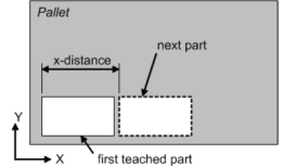
According to Figure 6-55, the defaulted palletizing sequence starts from X. Arrange all the parts in the x direction first, and then the next row. Arrange the workpiece in the x direction until the pre-determined number of workpieces in the x direction is reached.
Figure 6-57 The defaulted palletizing order
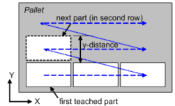
When starting placement for a new row, the position data of the workpiece in the new row will be produced by adding the offset in the y direction to the position of the workpiece in the first row.
The default palletizing sequence is x y z. First, put the workpiece in the x direction and then proceed to the second row. The placement of the first part of the new row starts at the position shown in the figure below. They will be put on the next row if the current row is full. After all the rows in this layer are filled, the xy layer repeats translation in the z direction until it is fully palletized.
Figure 6-58 illustrates the recommended path for placement.
Figure 6-58 Path for placement
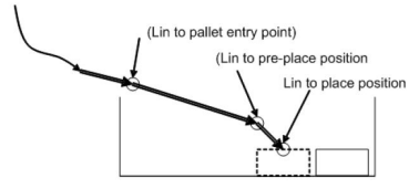 Following motion commands are executed when PalletToPut command is called:
The robot moves to the entry position of the pallet in a linear motion (optional)
The robot moves to the front position of the palletizing point in a linear motion (optional)
The robot moves to the arranged position of the workpiece in a linear motion (required)
PalletFromPut - Move Away from Placement command
This is the command used when the robot moves away from the putting position after the workpieces are placed.
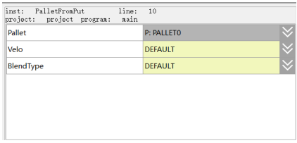
Palletizing name: The PALLET variable of the current pallet.
Target speed: The running speed of command.
− When setting it to “DEFAULT”, the default value V4000 will be used.
− When it is set to SPEED variable, you can select the system pre-defined one, or create it by yourself.
Transition type: The way of transition when the robot approaches the endpoint.
− DEFAULT: Default, i.e. no transition parameter is set in the command. If the SetBlendParam parameter is used in the program, the transition operates according to the globally set transition parameter.
− FINE: Equivalent in effect to DEFAULT.
− RELATIVE: Relative transition. The transition parameter is a relative value that represents the percentage of the distance from the transition point to the path endpoint relative to the full length of the path.
− ABSOLUTE: Absolute transition. The transition parameter is an absolute value that represents the distance from the transition point to the endpoint of path. from the transition point to the endpoint of path.
Transition Value: The transition value when the robot approaches the endpoint.
− When setting it to “DEFAULT”, the default value C100 will be used.
− When it is set to ZONE variable, you can select the system pre-defined one, or create it by yourself; it means no transition when the variable value is 0; the greater the transition value, the larger the transition radius.

This is the command for the opposite action of workpiece placement, making the robot leaves from the position of the workpiece that has been placed.
The recommended path when leaving is shown in Figure 6-59.
Figure 6-59 The path for leaving upon placement
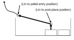
Following motion commands are executed when calling the PalletFromPut command:
- The robot moves to the rear of palletizing point in a linear motion (optional)
- The robot moves to the entry position of the pallet in a linear motion (optional)
If neither the post-pallet point nor the entry position has been set, the robot will maintain its current posture when the PalletFromPut command is executed.
PalletToGet – Pick Workpiece command
This is the command for picking the workpiece. When executing this command, the robot will move from the current point to the palletizing point of the target workpiece to Pick such workpiece.
Palletizing name: The PALLET variable of the current pallet.
Target speed: The running speed of command.
− When setting it to “DEFAULT”, the default value V4000 will be used.
− When it is set to SPEED variable, you can select the system pre-defined one, or create it by yourself.
Transition type: The way of transition when the robot approaches the endpoint.
− DEFAULT: Default, i.e. no transition parameter is set in the command. If the SetBlendParam parameter is used in the program, the transition operates according to the globally set transition parameter.
− FINE: Equivalent in effect to DEFAULT.
− RELATIVE: Relative transition. The transition parameter is a relative value that represents the percentage of the distance from the transition point to the path endpoint relative to the full length of the path.
− ABSOLUTE: Absolute transition. The transition parameter is an absolute value that represents the distance from the transition point to the endpoint of path. from the transition point to the endpoint of path.
Transition Value: The transition value when the robot approaches the endpoint.
− When setting it to “DEFAULT”, the default value C100 will be used.
− When it is set to ZONE variable, you can select the system pre-defined one, or create it by yourself; it means no transition when the variable value is 0; the greater the transition value, the larger the transition radius.

The recommended path for picking is shown in Figure 6-60.
Figure 6-60 Path for workpiece picking
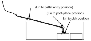
Following motion commands are executed when calling the PalletToGet command:
The robot moves to the entry position of palletizing point in a linear motion (optional)
The robot moves to the post position of the pallet in a linear motion (optional)
The robot moves to the picking position in a linear motion (required)
After making these motion sequences, the robot reaches the position where the workpiece is placed, then closes the fixture for picking workpieces.
PalletFromGet - Leave Pick Position command
This is the command indicating the process of leaving after workpiece pick. When executing this instruction, the robot will leave from the palletizing point where the workpiece is picked.
Palletizing name: The PALLET variable of the current pallet.
Target speed: The running speed of command.
− When setting it to “DEFAULT”, the default value V4000 will be used.
− When it is set to SPEED variable, you can select the system pre-defined one, or create it by yourself.
Transition type: The way of transition when the robot approaches the endpoint.
− DEFAULT: Default, i.e. no transition parameter is set in the command. If the SetBlendParam parameter is used in the program, the transition operates according to the globally set transition parameter.
− FINE: Equivalent in effect to DEFAULT.
− RELATIVE: Relative transition. The transition parameter is a relative value that represents the percentage of the distance from the transition point to the path endpoint relative to the full length of the path.
− ABSOLUTE: Absolute transition. The transition parameter is an absolute value that represents the distance from the transition point to the endpoint of path. from the transition point to the endpoint of path.
Transition Value: The transition value when the robot approaches the endpoint.
− When setting it to “DEFAULT”, the default value C100 will be used.
− When it is set to ZONE variable, you can select the system pre-defined one, or create it by yourself; it means no transition when the variable value is 0; the greater the transition value, the larger the transition radius.

The recommended path for picking is shown in Figure 6-61.
Figure 6-61 Path for leaving after picking
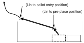
Following motion commands are executed when calling the PalletFromGet command:
The robot moves to the palletizing point in a linear motion (optional)
The robot moves to the entry position of the pallet in a linear motion (optional)
If neither the post-point nor the entry position of the pallet point has been set, the robot will maintain its current posture when executing the PalletFromGet command.
6.14 ARRAY commands
The list of ARRAY commands is shown in Figure 6-62.
Figure 6-62 List of ARRAY commands
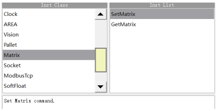
SetMatrix - Set Matrix System
Form a parallelogram in space with the specified three points and divide this parallelogram equally according to the set number of rows and columns to obtain a matrix point set.
Figure 6-63 Parameter editing interface of SetMatrix
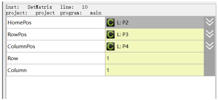
Origin: Specifies the first point of the parallelogram, of type CPOS.
Last point in row direction: Specifies the last point in the row direction of the parallelogram, of type CPOS.
Last point in column direction: Specifies the last point in the column direction of the parallelogram, of type CPOS.
Number of rows: The number of rows of the generated matrix, a constant, in the range [1,32767].
Number of columns: The number of columns of the generated matrix, a constant in the range [1,32767].
The matrix points generated based on the three points are only operations in the displacement direction, so the posture and additional axis angle values of the generated matrix points are kept the same as the origin (as in P1_Home below):
If the number of rows is 1 and the number of columns > 1, the line is divided equally according to the number of columns by forming a line based on the origin (as in P1_Home below) and the last point in the row direction (as in P2_Row below), disregarding the last point in the column direction (as in P3_Column below);
If the number of columns is 1 and the number of rows > 1, the line is divided equally according to the number of rows on the basis of the origin (as in P1_Home below, and the last point in the column direction (as in P3_Column below), disregarding the last point in the row direction (as in P2_Row below);
If both the number of rows and the number of columns are 1, the origin is used directly (as in P1_Home above);
The range of rows is [1,32767], the range of columns is [1,32767] and the product needs to be less than 32767.
Example 1:
Divide the quadrilateral formed by P1, P2 and P3 equally in 4 rows and 5 columns
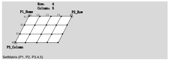
GetMatrix - Get Matrix Group
The value of this point in the corresponding row after executing the SetMatrix command and assigned to the target point. The posture and additional axis angle values of the point as described in SetMatrix remain the same as the origin.
Figure 6-64 GetMatrix parameter editing interface
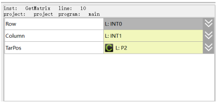
Number of rows: The row number of the matrix from which the point is to be taken, of type INT.
Number of columns: The column number of the matrix from which the point is to be taken, of type INT.
Target point: Used to store the value of the picked point, of type CPOS.
Note
The number of rows must be in the range [1,32767], the number of columns must be in the range [1,32767], and the number of rows and columns must be less than or equal to the corresponding values set in the SetMatrix command.
6.15 Socket commands
The list of Socket commands is shown in Figure 6-65.
Figure 6-65 List of Socket commands
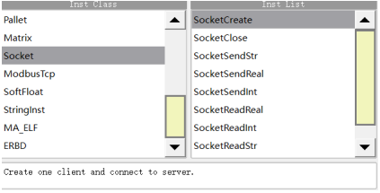
SocketCreate - Create Socket Client command
Create a socket client for purpose of data exchange with the server.
Create a client locally and connect it with the server-side according to the server-side parameters transmitted.
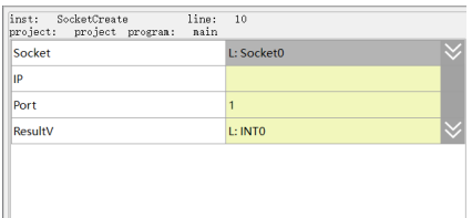
Socket name: The name of the socket to be created. The value transmits a socket variable.
IP address: The ip address of the server to be connected.
Port number: The port number of the server to be connected.
Operation return value: Create the return value variable of the operation. It is success if the return value is 0, and failed if it is 1.

SocketClose - Close Socket Client command
Close the socket client that has been created before.
Close the created client according to the socket name transmitted, and return the success or failure information of the operation.
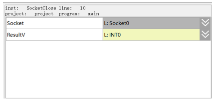
Socket name: The name of the socket to be closed. The value transmits a socket variable.
Operation return value: Create the return value variable of the operation. It is success if the return value is 0, and failed if it is 1.

SocketSendStr – Command to send a string via Socket
Send a string to the server for the interaction of commands.
Send a string to the server that has established a connection, and return the result of whether it is successful or not.
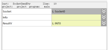
Socket name: The name of the socket that needs to perform the sending operation. The value transmits a socket variable.
Sent strings: The string data that needs to be sent to the server-side.
Operation return value: Create the return value variable of the operation. It is success if the return value is 0, and failed if it is 1.

SocketSendReal – Command to send a real array via Socket
Send a real array to the server for command interaction.
Send a real array to the connected server and return the success or failure.
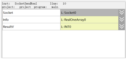
Socket name: The name of the socket that needs to perform the sending operation. The value transmits a socket variable.
Real-type array sent: The real-type array data that needs to be sent to the server-side.
Operation return value: Create the return value variable of the operation. It is success if the return value is 0, and failed if it is 1.

SocketSendInt - Command to send int array to Socket
Send an int array to the server for command interaction.
Send an int array to the connected server and return the success or failure.
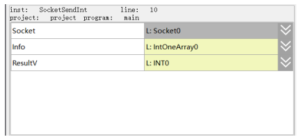
Socket name: The name of the socket that needs to perform the sending operation. The value transmits a socket variable.
int-type array sent: The real-type array data that needs to be sent to the server-side.
Operation return value: Create the return value variable of the operation. It is success if the return value is 0, and failed if it is 1.
SocketReadReal - Convert the string sent from the server into a Real array format for storage
Read the string sent from the server-side, and store it in the form of a real array.
Wait for and receive the string sent by the server. Its format is [1.1,2.2,3.3,4.4] (that is, the beginning and the end of the data are'[]', and the figures are separated by','). The robot system will split and parse the received string, and store it in the array in sequence.
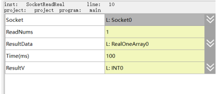
Socket name: The name of the socket that needs to perform the read operation. The value transmits a socket variable.
Read count of data: The count of data to be read and stored in the array.
Data return value: Store the read and converted value into an array variable, and return such array variable.
Detection time: The time for waiting for the server-side to send data. It sends alarm when time is out.
Operation return value: Create the return value variable of the operation. It is success if the return value is 0, and failed if it is 1.

SocketReadInt - Convert the string received from the server into an integer format
Read the string sent from the server and store it in the form of an int array.
Wait for and receive the string sent by the server-side. Its format is [1,2,3,4] (the beginning and the end of the data are'[]', and the figures are separated by','). The robot system will split and parse the received string, and store it in the array in sequence.
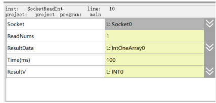
Socket name: The name of the socket that needs to perform the read operation. The value transmits a socket variable.
Read count of data: The count of data to be read and stored in the array.
Data return value: Store the read and converted value into an array variable, and return such array variable.
Detection time: The time for waiting for the server-side to send data. It sends alarm when time is out.
Operation return value: Create the return value variable of the operation. It is success if the return value is 0, and failed if it is 1.

SocketReadStr- Read the string sent by the server and store it as a string variable
Read the string sent from the server-side, and store it in the form of a string variable.
Wait and receive the string sent by the server. Its format is [Hello world!] (The beginning and the end of the data are'[]'). The robot system will store the received string in the string variable.
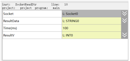
Socket name: The name of the socket that needs to perform the read operation. The value transmits a socket variable.
Read string: The string data sent from the server. The value is returned in the form of a string variable.
Detection time: The time for waiting for the server-side to send data. It sends alarm when time is out.
Operation return value: Create the return value variable of the operation. It is success if the return value is 0, and failed if it is 1.

SocketResetBuf - Reset locally cached strings
This command is used to reset local cache strings. It is intended to reset the data already received in the cache before the SocketRead read command is executed, to avoid the problem of misplaced data reading.
Socket name: The name of the socket that needs to perform the read operation. The value transmits a socket variable.
For example:

6.16 ModbusTCP commands
The list of ModbusTCP commands is shown in Figure 6-66.
Figure 6-66 List of Modbus commands
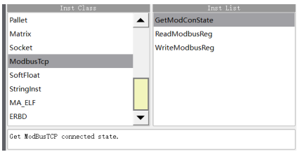
GetModConState - Get the connection status of the connection to ModbusTCP
This command is used to get the status of the robot's connection to the external world using ModbusTCP communication.
Figure 6-67 GetModConState parameter editing interface
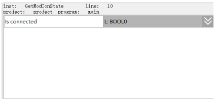
Connection status: Return the current connection status, of type BOOL.
ReadModbusReg - Read the specified Modbus register value
This command is used to read the value of the specified Modbus register.
Figure 6-68 ReadModbusReg parameter editing interface
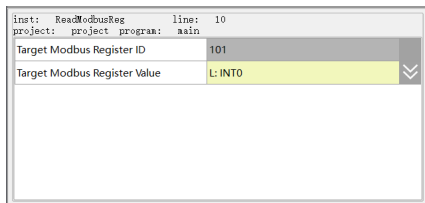
Target register ID number: The register ID number to be read, of type INT.
Target register value: Return the value of the register after reading, of type INT.
WriteModbusReg - Set the specified Modbus register value
This command is used to set the value of the specified Modbus register.
Figure 6-69 WriteModbusReg parameter editing interface
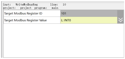
Target register ID number: The register ID number to be modified, of type INT.
Target register value: The register value to be modified, of type INT.
6.17 SoftFloat commands
The list of SoftFloat commands is shown in Figure 6-68.
Figure 6-70 List of SoftFloat commands
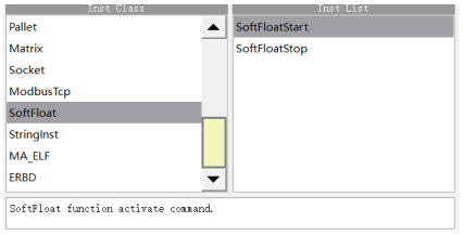
SoftFloatStart – Command to start SoftFloat
This is the command for SoftFloat start. Turn on the SoftFloat function and set the parameters.
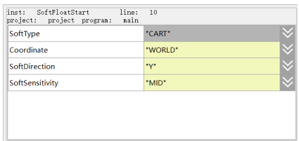
Type of SoftFloat:
− Linear SoftFloat. Only the linear SoftFloat is supported currently.
SoftFloat reference coordinate system:
− WORLD: World Coordinates
− USER: Tool Coordinates
− TOOL: User Coordinates
Coordinate system number: When WORLD is selected as the reference coordinate system, the coordinate system number is empty by default and will not be displayed. When TOOL or USER is selected, select an existing coordinate system number from the drop-down list, or create a new coordinate system number in the pop-up dialog box for teaching.
SoftFloat direction:
− X: The X direction of the selected reference coordinate system or its number
− Y: The Y direction of the selected reference coordinate system or its number
− Z: The Z direction of the selected reference coordinate system or its number
SoftFloat sensitivity: The SoftFloat compliance parameter.
− HIGH: The highest level of compliance
− MidHigh: The second highest level of compliance
− MID: The medium compliance
− MidLow: The second lowest level of compliance
− LOW: the lowest level of compliance
For the setting of SoftFloat direction, please refer to the description of SoftFloat functions for details.

SoftFloatStop – Command to stop SoftFloat
This is the command for SoftFloat ending. Use this command to turn off the SoftFloat function.
After the SoftFloat function is done, call this command to turn off the SoftFloat function.

6.18 Online load tuning commands
The online load tuning function of robot. It is designed to get the dynamics information (including load mass, center of mass and inertia tensor) of the load mounted on the flange end of the robot online, and the resultant load dynamics information can be used to calculate the robot dynamics model, which can improve the robot performance and improve the problems such as over torque alarm of joints, false alarm of collision detection and jitter during robot motion caused by the mismatch of load information.
Figure 6-71 Online load tuning commands
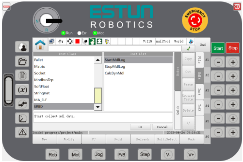
StartMdILog – Command to start collecting dynamic mechanical model tuning data
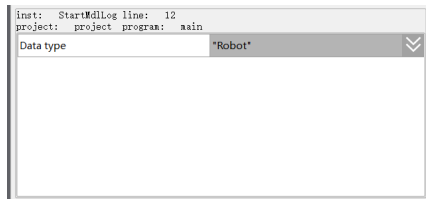
Type of stored data:
- Robot: Optional data collection, which collects motion data from the robot itself, i.e. the motion data when no load is attached. The use of "Robot" type data for tuning helps to improve the accuracy of load tuning, but this item increases the time taken for tuning calculations.
- WithLoad: data must be collected to capture the motion of the robot with a load mounted on the flange end;
- ValidData: Optional data collection, selected when the accuracy of the model needs to be verified, to collect data on the motion of the robot fitted with a load. Using the "ValidData" type of data allows you to verify the accuracy of the tuned model at the same time as the tuning calculation; however, this item will increase the time taken for the tuning calculation.
Note
The load tuning data collection. When selecting "Robot", "WithLoad" as the data saving type, the motion command used to validate the path should be MovJ; the MovJ, MovL, MovC and other combinations can be used when verifying the motion path for "ValidData" type.
The TRIGGER command does not support single- step or manual mode.
StopMdlLog – Command to abort the acquisition of kinetic model tuning ata
Note
This command must be used in conjunction with the StartMdllog() instruction.
After the execution of StopMdllog(), a ".txt" file with the same name as the StartMdllog() parameter, i.e. the data saving type, will be generated in the "runtime\config" directory, and the file can be opened by the software EScope to view the curves.
The TRIGGER command does not support single-step or manual mode.
CalDynMdl – Command to set model tuning parameters
The command for online robot load tuning calculation. It is used to recognize the robot load information.
Once the data required for load tuning has been collected, execute this command to start the robot load tuning process, which takes 30-60 minutes. Once tuning is done, a pop-up box will display the model validation score results.
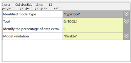
Command paramters are required to execute this function: type of model to be tuned, workpiece load variable, length of data interval, and whether to validate the model. The command parameters are detailed below:
The type of model to be tuned:
- Type "TypePayload" is used to tune the load parameters;
- Type "TypeTool" is used to tune the tool parameters;
Workpiece load variable: The variable used to store the tuning results (PAYLOAD load variable or TOOL tool variable);
Data interval length: set the interval parameter for extracting valid tuning data from the original data, the greater the value the less data used for tuning, the less accurate the load tuning results will be, ranged as [0, 100];
Whether model validation is required: Whether model validation is required for load tuning. If the value is set to "Enable l", and model validation is required, then you should set the data acquisition command StartMdlLog() and select "ValidData type to collect a set of model validation data.
Note
TRIGGER commands do not support single step and manual mode.
The online load tuning function is currently only supported on the Universal 6-axis model.
The online load tuning function only runs on a controller system with more than 1GB of C drive space and 1GB of Windows memory, otherwise the function will not work properly;
6.19 STRING commands
The list of STRING commands is shown in Figure 6-72.
Figure 6-72 List of STRING commands
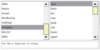
byte
Take the ASCCII code of the character in the nth position of the string.
Parameter 1: The variable or constant of string type.
Parameter 2: The variable or constant of type int.
Function return value: The int-type constant.
find2
Return the position of the substring in the string.
Parameter 1: The variable or constant of string type.
Parameter 2: The variable or constant of type int.
Function return value: The int-type constant. (The return value is -1 when the corresponding character or string is not found)
len
Calculate the length of a string.
Parameter 1: The variable or constant of string type.
Function return value: The int-type constant.
char
Return the character corresponding to the ASCCII code.
Parameter 1: The variable or constant of type int.
Function return value: The constant of string type.
gsub
Search for substring a within string s and replace a with string b.
Parameter 1: The variable or constant of string type.
Parameter 2: The variable or constant of string type.
Function return value: The constant of string type.
lower
Return the string in lowercase format.
Parameter 1: The variable or constant of string type.
Function return value: The constant of string type.
upper
Return the string in uppercase format.
Parameter 1: The variable or constant of string type.
Function return value: The constant of string type.
reverse
The string inversion command, which inverts the string and returns it.
Parameter 1: The string to be inverted, a variable or constant of type string.
Function return value: The string to be inverted, a string variable.
findEnd
The string inversion lookup command, which locates the last occurrence of a specified string in a string and returns the index number.
Parameter 1: The source string to be looked up, a variable or constant of type string.
Parameter 2: The specified string to be looked up, a variable or constant of type string.
Return value: The index number of the search, a variable of type int.
format
The formatted STRING command, which transmits a reasonable formatting control in parameter 1, fills this formatting control with any number of subsequent parameters, and returns the filled data.
Parameter 1: The String format, a variable or constant of type string.
Parameter 2: The parameter of the formatting controller to be filled, a variable or constant of type string/real/int.
Parameter 3: The parameter of the formatting controller to be filled, a variable or constant of type string/real/int.
... (no limit on the number of parameters, as long as the total length does not exceed the length of a single commanded string)
Function return value: The count of successfully split and saved to an array, a variable of type int
The formatted string starts with % and supports the following uses.
%c - accepts a number and converts it to the corresponding character in the ASCII table
%d, %i - accepts a number and converts it into signed integer format
%o - accepts a number and converts it to octal format
%u - accepts a number and converts it to unsigned integer format
%x - accepts a number and converts it to hexadecimal format, using the lowercase letter x
%X - accepts a number and converts it to hexadecimal format, using an uppercase X
%f - accepts a number and converts it to floating point format
%s - accepts a string and formats it according to the given parameters
Example:
format("%%c: %c", 83) Output S
format("%+d", 17.0) Output +17
format("%05d", 17) Output 00017
format("%o", 17) Output 21
format("%u", 3.14) Output 3
format("%x", 13) Output d
format("%X", 13) Output D
format("%6.3f", 13) Output 13.000
format("%s", "monkey") Output monkey
format("%10s", "monkey") Output monkey
getAt
The command to obtain a single string. It gets the string data of a certain bit and returns the obtained data.
Parameter 1: The string to be intercepted, a variable or constant of type string.
Parameter 2: The position to be intercepted, a variable or constant of type int.
Function return value: The acquired string, a variable of type string.
left
The command to take the left of a string. It intercepts a specified number of strings starting from the left side of the string and returns the intercepted data.
Parameter 1: The string to be intercepted, a variable or constant of type string.
Parameter 2: The number to be intercepted, a variable or constant of type int.
Function return value: The intercepted string, a variable of type string.
right
The command to take the right of a string. It intercepts a specified number of strings starting from the right side of the string and returns the intercepted data.
Parameter 1: The string to be intercepted, a variable or constant of type string.
Parameter 2: The number to be intercepted, a variable or constant of type int.
Function return value: The intercepted string, a variable of type string.
strcmp
The String comparison command. Under this command, the return value is the ASCII difference between the first different characters.
Parameter 1: The string data to be compared, a variable or constant of type string.
Parameter 2: The string data to be compared, a variable or constant of type string.
Function return value: The returned ASCII value, a variable of type int.
trimLeft
The command to trim the string by left. This command removes the spaces to the left of the string and returns the modified string data.
Parameter 1: String to be trimmed, a variable or constant of type string.
Function return value: The trimmed string, a variable of type string.
trimRight
The command to trim the string by right. This command removes the spaces to the right of the string and returns the modified string data.
Parameter 1: String to be trimmed, a variable or constant of type string.
Function return value: The trimmed string, a variable of type string.
IToStr
Integer data to STRING command. The command allows to convert integer data to string type data and return the converted string.
Parameter 1: The integer data to be converted, a variable or constant of type int.
Function return value: The converted string data, a variable of type string.
RToStr
REAL parameter to STRING command. The command allows to convert the real data to string type data and return the converted string.
Parameter 1: The real data to be converted, a variable or constant of type REAL.
Function return value: The converted string data, a variable of type string.
StrToI
The String to Integer command. This command converts string data to integer type data and returns the converted integer data.
Parameter 1: The string data to be converted, a variable or constant of type string.
Function return value: The converted integer data, a variable of type int.
StrToR
The String to REAL data command. This command converts string data to REAL type data and returns the converted real number.
Parameter 1: The string data to be converted, a variable or constant of type string.
Function return value: The real data to be converted, a variable of type REAL.
APosToStr
The APOS point data to STRING command. This command converts apos points into strings in the specified format and returns the converted string data. The converted apos point is in the format "0; 1,2,3,4,5,6,0,0,0,0,0,0,0,0,0,0,0;", where the semicolon in front represents the apos point type and coordinate value, respectively.
Parameter 1: The APOS point data to be converted, a variable of type APOS.
Function return value: The converted string data, a variable of type string.
CPosToStr
The CPOS point data to STRING command. This command converts cpos points into strings in the specified format and returns the converted string data. The converted cpos point is in the format "1;0,0,0,0,0,0;1,2,3,4,5,6,0,0,0,0,0,0,0,0,0,0;", where the semicolon in front represents the cpos point type, cfg parameter and coordinate value, respectively.
Parameter 1: The CPOS point data to be converted, a variable of type CPOS.
Function return value: The converted string data, a variable of type string.
TranStrToInt
The command to get integer string array. This command splits the string according to the passed split character, converts the split value to an integer one-dimensional array and returns the number of valid splits.
Parameter 1: The string to be split, a variable or constant of type string.
Parameter 2: The separator, a variable or constant of type string.
Parameter 3: The split integer being stored as an array, a variable of type IntOneArray.
Function return value: The count of successfully split and saved to an array, a variable of type int
Example:
P:INT0.value = TranStrToInt("1_2_3er", "_", G:IntOneArray0) // The command passes in the character "1_2_3er", and after execution the system extracts the data by splitting it according to the incoming split character '_'. The split data is stored in the one-dimensional integer array variable IntOneArray0 in the order of 1, 2, 0, and the number of splits 3 is assigned to INT0.value.
TranStrToReal
A command to get an array of REAL strings. This command splits the strings according to the passed splitters and converts the split values into a REAL one-dimensional array and returns the number of valid splits.
Parameter 1: The string to be split, a variable or constant of type string.
Parameter 2: The separator, a variable or constant of type string.
Parameter 3: Store the split REAL type variable as an array, a variable of type RealOneArray.
Function return value: The count of successfully split and saved to an array, a variable of type int
Example:
P:INT0.value = TranStrToReal("1.1_2.2_3er", "_", G:IntOneArray0) // The command passes in the character "1.1_2.2_3er", after execution the system extracts the data by splitting it according to the incoming split character '_'. The split data is stored in the one-dimensional integer array variable RealOneArray0 in the order of 1.1, 2.2, 0 respectively, and the number of splits 3 is assigned to INT0.value.
TranStrToApos
The command to get an array of apos point data strings. This command splits the string according to the passed split character and converts the split value to an apos point variable, while returning a status of whether the conversion was successful or not. The string to be converted must be in the format "0; 1,2,3,4,5,6,0,0,0,0,0,0,0,0,0,0,0;", where the leading semicolon represents the apos point type, the coordinate value, and the last semicolon can be followed by any string.
Parameter 1: The string to be split, a variable or constant of type string.
Parameter 2: The separator, a variable or constant of type string.
Parameter 3: Store the split apos point data as an apos variable, a variable of type APOS.
Function return value: Return the status of the extraction success or failure, a variable of type int
Example:
P:INT0.value = TranStrToApos("0; 21,22,23,24,25,26,0,0,0,0,0,0,0,0,0,0;$qwqewe", "$", G: P0) // The command passes in the characters "0;21,22,23,24,25,26,0,0,0,0,0,0,0,0,0,0,0,0;$qwqewe". After execution, the system will split the extracted data according to the incoming separator '$', and the data after '$' will be discarded. The split data are stored in the order 21, 22, 23, 24, 25, 26... in the order of a1, a2, a3, a4, a5, a6... of P0. and the successful return value 0 is assigned to INT0.value.
TranStrToCpos
The command to get an array of cpos point data strings. This command splits the string according to the incoming separator and converts the split value to an apos point variable, while returning a status of whether the conversion was successful or not. The string to be converted must be in the format "1;0,0,0,0,0,0,0;1,2,3,4,5,6,0,0,0,0,0,0,0,0,0,0,0,0;", with the semicolon preceding the cpos point type, the cfg parameter, and the coordinate value respectively.
Parameter 1: The string to be split, a variable or constant of type string.
Parameter 2: The separator, a variable or constant of type string.
Parameter 3: Store the split apos point data as a cpos variable, a variable of type CPOS.
Function return value: Return the status of the extraction success or failure, a variable of type int
Example:
P:INT0.value = TranStrToCpos("1;0,0,0,0,0,0;21,22,23,24,25,26,0,0,0,0,0,0,0,0,0,0;$qwqewe", "$", G: P0) //
The command passes in the characters "0; 0,0,0,0,0,0,0;21,22,23,24,25,26,0,0,0,0,0,0,0,0,0,0,0,0,0,0;$qwqewe". After execution, the system will split the extracted data according to the passed splitting character '$', the data after '$' will be discarded. The data after the first ";" will be stored in the cfg parameter in the order of "0,0,0,0,0,0" and the data after the second ";" will be stored in the order of 21, 22, 23, 24, 25, 26... in the order of x, y, z, a, b, c... of P0, and the successful return value 0 is assigned to INT0.value.
6.20 Mathematical Functions
The mathematical functions or string operating functions may be used in the "IF" and "...=..." commands.
This section explains the "Mathematical Functions" that may be used.
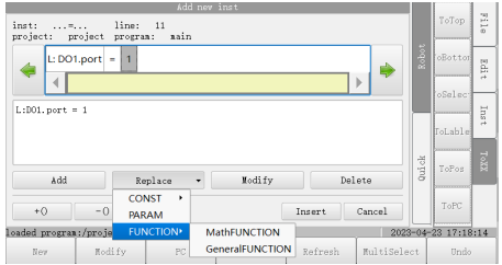
sin - Sine trigonometric function
The sine trigonometric function.
Parameter 1: A variable or constant of type int or REAL.
Function return value: A constant of type REAL.
cos - Cosine trigonometric function
The cosine trigonometric function.
Parameter 1: A variable or constant of type int or REAL.
Function return value: A constant of type REAL.
tan - Tangent trigonometric function
The tangent trigonometric function.
Parameter 1: A variable or constant of type int or REAL.
Function return value: A constant of type REAL.
asin – Inverse sine trigonometric function
The inverse sine trigonometric function.
Parameter 1: A variable or constant of type int or REAL.
Function return value: A constant of type REAL.
acos – Inverse cosine trigonometric function
The inverse cosine trigonometric function.
Parameter 1: A variable or constant of type int or REAL.
Function return value: A constant of type REAL.
atan – Inverse tangent trigonometric function
The inverse tangent trigonometric function.
Parameter 1: A variable or constant of type int or REAL.
Function return value: A constant of type REAL.
atan2 - X/Y Inverse tangent function
X/Y inverse tangent value function, returning the value in radian from the X axis to the point (x, y).
Parameter 1: A variable or constant of type int or REAL.
Parameter 2: A variable or constant of type int or REAL.
Function return value: A constant of type REAL.
sinh - Hyperbolic sine function
The hyperbolic sine function.
Parameter 1: A variable or constant of type int or REAL.
Function return value: A constant of type REAL.
cosh – Hyperbolic cosine function
The hyperbolic cosine function.
Parameter 1: A variable or constant of type int or REAL.
Function return value: A constant of type REAL.
tanh - Hyperbolic tangent function
The hyperbolic tangent function.
Parameter 1: A variable or constant of type int or REAL.
Function return value: A constant of type REAL.
log - Logarithmic function
The natural logarithmic function.
Parameter 1: A variable or constant of type int or REAL.
Function return value: A constant of type REAL.
log10 - Logarithmic function of base 10
The logarithmic function of base 10.
Parameter 1: A variable or constant of type int or REAL.
Function return value: A constant of type REAL.
sqrt - Square root function
The square root function.
Parameter 1: A variable or constant of type int or REAL.
Function return value: A constant of type REAL.
exp - Exponential function of base e
The exponential function of base e.
Parameter 1: A variable or constant of type int or REAL.
Function return value: A constant of type REAL.
pow - Exponential function
The exponential function/
Parameter 1: int or real type variables or constants, base.
Parameter 2: int or real type variables or constants, exponent.
Function return value: The real constants.
deg - Radian to Degree Function
The radian to degree function.
Parameter 1: A variable or constant of type int or REAL.
Function return value: A constant of type REAL.
rad - Degree to Radian Function
The degree to radian function.
Parameter 1: A variable or constant of type int or REAL.
Function return value: A constant of type REAL.
fmod - Remainder Function
The remainder function.
Parameter 1: int or real type variables or constants, dividend.
Parameter 2: int or real type variables or constants, divisor.
Function return value: The real constants.
floor - Floor function
The floor function.
Parameter 1: A variable or constant of type int or REAL.
Function return value: A constant of type int.
random - Random integer
Random integers selected from one of the 2 parameters.
Parameter 1: A variable or constant of type int or REAL.
Parameter 2: A variable or constant of type int or REAL.
Function return value: A constant of type int.
6.21 Other functions
Other functions may be used in the "IF" commands and the "...=..." commands. "Other functions" that can be used are given in this section.
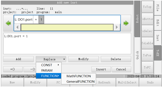
SimAiToReal
A function that converts SimAi variables to Real types that can be involved in arithmetic after conversion.
Parameter: SimAi
Function return value: A constant of type Real.
SimAoToReal
A function that converts SimAo variables to Real types that can be involved in arithmetic after conversion.
Parameter: SimAo
Function return value: A constant of type Real.
No comments to display
No comments to display