
3. Product Use
It is necessary to install and connect the product before use.
3.1 Connection methods
Prior to use, please ensure that the robot, control cabinet and teach pendant are properly connected and that the equipment is available. For connection methods, please refer to the Instruction Manual for Mai Unit of ESTUN's XX Series Robots.
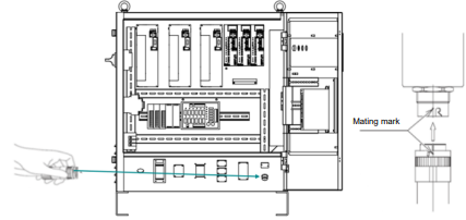
Complete the connection of the robot, the control cabinet and the programming pendant by referring to the following steps.
Step 1 Unpack, connect the power cable to the control cabinet power supply.
Step 2 Connect the robot to the control cabinet with the interconnection cable.
Step 3 Check the shape and size of the cable connectors and the position of the sockets on the robot, insert the cable into the appropriate socket and secure it firmly.
Step 4 Connect the cable from the programming pendant to the interface of the control cabinet's teach pendant
----END
3.2 Operating instructions
3.2.1 Robot coordinates
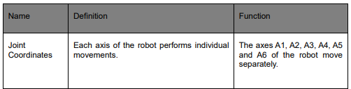
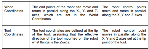
The main types of robot coordinates are as follows:
Joint Coordinates
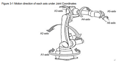
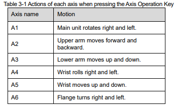
When operating in joint coordinates mode, the A1, A2, A3, A4, A5 and A6 axis of the robot moves independently. The motion direction of each axis under joint coordinates is shown in Figure 3-1.
The actions of each axis when pressing the Axis Operation Key are listed in Table 3-1.
World Coordinates
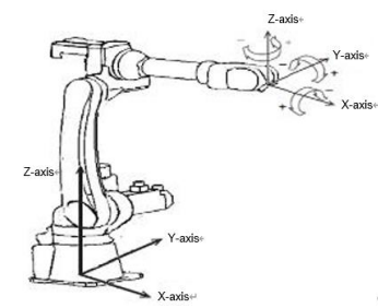
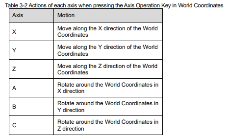
In the World Coordinates, the control point of robot moves parallel to the X-, Y-, or Z-axes. The motion direction of each axis is shown in Figure 3-2.
Figure 3-2 Motion direction of each axis under World Coordinates
Actions of each axis when pressing the Axis Operation Key are as shown in Table 3-2.
Tool Coordinates
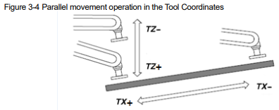
The tool coordinates are defined at the tip of the tool, assuming that the effective direction of the tool mounted on the robot wrist flange is the Z-axis. When it is set to Tool Coordinates, the robot control point moves in parallel along the X-, Y-, and Z-axes set at the tip point of the tool.
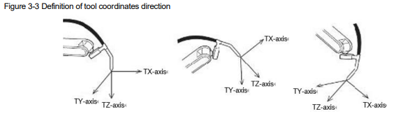
When the Axis Operation Key is pressed, the motions of each axis are shown in Table 3-3
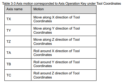
The movement of tool coordinates is based on the effective direction of the tool, but has no connection with the position and posture of the robot. In this case, it would be most suitable for parallel movement operations without changing the posture of the tool relative to the workpiece.
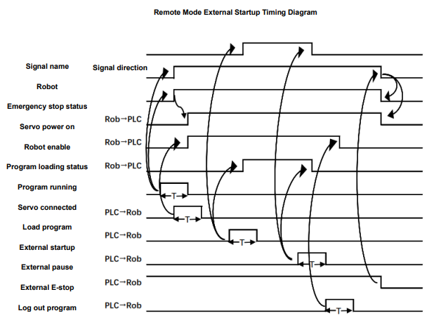
3.3 Start/stop sequence
Figure 3-5 Start/stop sequence diagram of the robot controller
3.3.1 Teaching
Precautions
1. After the mode knob is turned to manual mode under programming pendant mode, users may hold tightly the safety switch in case of mis-operation for its human instinctive reaction. The safety switch is of a two-stage switch, and the servo will be powered off when pressing it to stage 2.
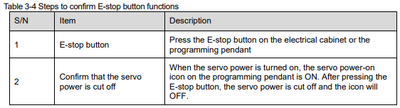
Confirmation of emergency stop
Before operating the robot, press the E-stop button on both the electrical cabinet and the programming pendant to confirm whether the servo power is cut off.

Preparation for teaching
Perform the following tasks before starting to teach.
Check the electric control cabinet and the main unit, for example, if the power cord, servo port and controller port of the control cabinet are properly connected, and if there are foreign objects on the main unit.
Start the electric control cabinet and confirm that all parts are in proper working condition. (For details, please refer to 2.2 Control cabinet)
Turn on the main power of the servo, and test the E-stop keys on the electric control cabinet and the programming pendant.
Turn the mode switch on the programming pendant to teaching mode.
Press the manual switch at this time to perform the axis operation using the axis operation keys (for the axis motion corresponded to the Axis Operation Key, see 3.2.1 Robot coordinates).
Basic steps for teaching
Create New Job
When teaching, you can record the taught robot trajectory through commands. When replaying, the teaching action can be replayed by using the recorded commands. The steps for creating a new job are as follows.
Step 1 Click  , or the “Project Management” in the main interface to enter to the Projec
Step 2 Click "Create", and the "New Job" dialog box will pop up, as shown in Figure 3-6.
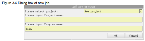
Step 3 Select "New Job" from the drop-down list to the right of "Please select a job".
Step 4 Click the input box of "Please enter the job name", and enter the name of the job to be created in the popup soft keyboard, i.e. project0.
Step 5 Click the input box of "Please enter the job name", and enter the name of the job to be created in the popup soft keyboard, i.e. program0.
Step 6 Click "OK" to create a new job or program successfully, and the interface jumps directly to the Job Editing interface, as shown in Figure 3-7.
Figure 3-7 Job editing interface
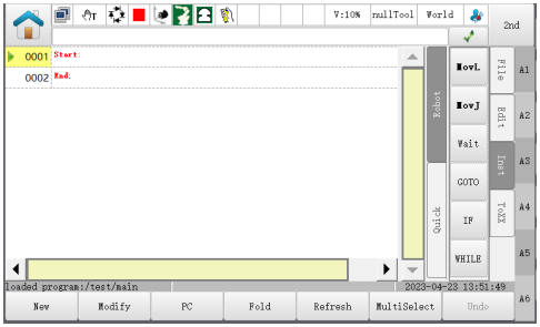
Step 7 Edit commands in the job interface. The commands that control the robot's motion are motion commands. In the movement instructions, the position of the movement, the interpolation mode, the playback speed, etc. are recorded (for other types of commands, please refer to the appendix “Types of Basic Commands”).

----END
Teaching overview

The program describes the robot's work using the robot language. Now input the following processing program from Point A to B for the robot. This program consists of 6 steps from 1 to 6.
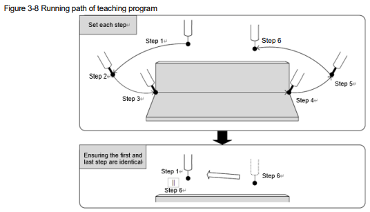
Step 1: Start Position
Move the robot to a safe work position away from surrounding objects, and enter Step 1.
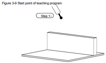
Step 1 Grip the enable switch, and move the robot to the start position using the Axis Operation Keys. Set the starting position at a safe position suitable for job preparation.
Step 2 Press the "Create" button in the job interface, and select "Motion Command→MovJ" from the list.
Step 3 Click "OK" to enter the command editing interface of MovJ, as shown in Figure 3-10.
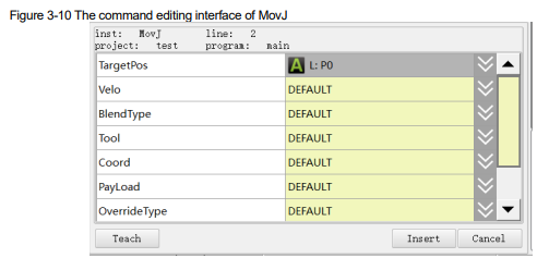
Step 4 After clicking "Teach", Point P1 records the robot sitting posture at Step 1 by this moment. Step 1 is taught after clicking "Insert", and the commands displayed in the program interface are as follows:

----END
Step 2: Near the Work Start Position
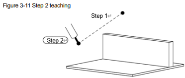
Make the robot in the work posture using Axis Operation Keys. Teach step 2 by utilizing the method of teaching step 1: starting position. The program commands are as follows upon teaching:

Step 3: Work Start Position
Move the robot to the work start position (Step 3) with the pose as shown in Step 2.
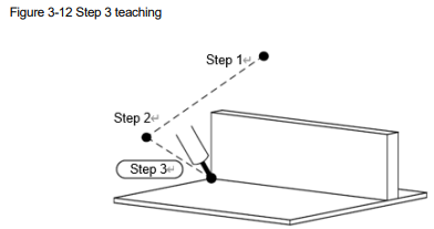
Step 1 Keep the posture of Step 2 the same, and click  . Set the robot coordinate system to a World Coordinates, and move the robot to the starting position of the job using the axis operation keys.
Step 2 Press "Create" in the job interface, to enter the command interface and select the linear interpolation command.
Step 3 Click "Teach" to have the teaching of Step 3 done. The program commands are as follows.

----END
Step 4: Work End Position
Specify the work end position.
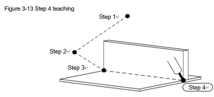
Move the robot to the work end position with the Axis Operation Keys. While the robot is moving from starting position to the end position, keep a wide enough distance to ensure it will not strike the workpiece.
Use the method in the same way as the teaching Step 1 by adding a linear interpolation command. P4 is the sitting posture of the robot at Step 4. The program commands are detailed as follows.

Step 5: Position Away from Workpiece and Fixture
Move the robot to a position where it will not strike the workpiece or fixture.
Figure 3-14 Step 5 teaching
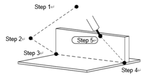
Move the robot with the Axis Operation Keys to a position where it will not strike the fixture. Use the method in the same way as the teaching Step 1 by adding a linear interpolation command. P5 is the sitting posture of the robot at Step 5. The program commands are detailed as follows:

Step 6: Near the Start Position
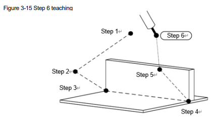
Move the robot with the Axis Operation Keys to a position near the start position in the Joint Coordinates.
Use the method in the same way as the teaching Step 1 by adding a linear interpolation command. P6 is the sitting posture of the robot at Step 6. The program commands are detailed as follows:

Ensuring the First and Last Step are Identical
The robot has stopped at Step 6, which should be very close to Step1. It is possible to move directly from the welding end position of Step 5 to Step1, so that the robot can begin the next welding job quickly and efficiently.
The following operation will make Step 6 (end position) and Step1 (start position) identical.
Figure 3-16 Modify Step 6 to Step 1
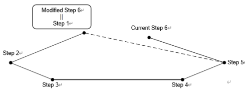
Step 2 Move the cursor to Step 1; click "Set Pointer" button, press "Step" to select the single-step mode. After setting the speed within 10%, press "Start" and the program starts to run, then move the robot to Step 1.
Step 3 Move the cursor to Step 6. After pressing "Modify", the modification interface appears.
Step 4 Press “Teach” key. This will change the position of Step 6 to be the same as Step1.
----END
Path confirmation
The job is now complete. Please run the next job, and try to check each step separately to ensure there are no problems. When confirming the path, make sure that the programming pendant is in the teaching mode, and the enable switch is pressed at time of motion.
Step 1 Move the cursor to Step 1, and click “PC”.
Step 2 Click  to choose the single-step mode.
Step 3 Press the speed increase and decrease keys to set the speed within 10%.
Step 4 Press the enable switch, and the robot servo enables.
Step 5 Press  , and the program starts operation in single-step mode. The robot runs a command program each time you pressing the
 .
Step 6 When you finish step confirmation, move the cursor to the beginning of the job.
Step 7 Press  to run all the steps continuously. After pressing
 , the robot plays back all the steps continuously and stops when one cycle is finished.

When running a path in teaching mode, the trajectory speed is limited by the national standard speed, with a maximum linear speed of 250mm/s and a maximum posture speed of 180deg/s
----END
Correcting a Job
If the actual robot trajectory differs from the expected one, the robot's trajectory can be adjusted by modifying the step position and speed in a job.
Before Correction
Confirm the robot’s motion in each step. If any position modification or adding or deleting of steps is necessary, edit the job content by following the procedures below.
Step 1 Press  , or the “Project Management” on the main interface to enter the Project Management interface.
Step 2 Select the job to be edited.
Step 3 Click "Load" and enter the job editing interface.
----END
Changing the Position Data
Change the position registered in Step 2.
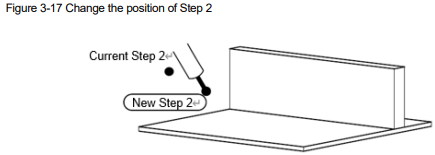
Step 1 Using the above method, set it to single-step mode set the speed within 10%, and press  to move the robot to Step 2 to be modified. The robot moves a step by pressing the
 once.
Step 2 Move the robot to the modified position with the Axis Operation Keys, as shown in the new Step 2 in Figure 3-17.
Step 3 Press “Modify” to enter the point correction interface.
Step 4 Press “Teach”. The step’s position data is changed.
----END
Adding a Step
Add a new step between two steps. For example, add a step between Step 5 and Step 6 as follows.
Step 1 Move the robot to Step 6 by pressing  . Make sure that the robot can move to position 6 from the current position without collision before moving.
Step 2 Move the robot to the position at which you wish to add a step using the Axis Operation Keys.
Step 3 Add a joint interpolation command with reference to the “Adding Step 1”.
----END
Deleting a Step
Delete the step you just added. Return to the state on the original right picture from the state on the right picture below.
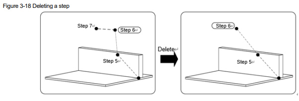
Enter the job editing interface; click the command to be deleted; then click "Delete" on the right, and "OK" in the "Delete a Command” prompt box.
3.3.2 Playback
Preparation before playback
Precautions:
Check that there are no operators or other staff in the work area before operation.
Check that the E-stop buttons on the teach pendant and control cabinet is inactive.
The program after the teaching execution is called Playback. Before playback, make sure that the following is done:
Step 1 Make sure that the operator and other staff are outside the working envelope of robot prior to re-operation.
Step 2 Make sure that the E-stop keys on the electric control cabinet and the programming pendant are in an invalid state.
Step 3 Load the project file for playback.
Step 4 Select the program to be executed first, and then click "PC" to ensure that the program is executed from the first line.
Step 5 Press the speed increase or decrease key to set the speed to the desired.
----END
Playback procedure
Step 1 Set the mode knob on the programming pendant to Auto mode, and move the cursor to the beginning of the program.
Step 2 Click the  , and power on the servo.
Step 3 Click the  , and the robot will stop after one cycle of program under the playback.
----END
Stop and restart
Causes for stopping the robot in motion or enabling the robot to stop automatically are detailed as follows:
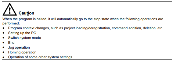
Stop operation or emergency stop temporarily
Stop by alarm
Other stops
Stop by the operations
Start-stop specifications
1. Do not switch the power on and off frequently, as this may damage the drive. Each time the power is switched on and off, the time interval should be 60s or above.
2. Before powering off, please ensure that the machine is in a stopped state. Stop the program before powering off.
Hold
Stops using the programming pendant
− Hold
Press  on the programming pendant, and the robot stops.
− Release
Press  on the programming pendant. The robot restarts its operation from the position where it was stopped.
Stops using an external input signal (system input)
− Hold
Turn ON the hold signal from an external input. The robot stops temporarily.
− Release
Turn off the hold signal from an external input. The robot restarts its operation, beginning from the position where it was stopped
Emergency Stop
An emergency stop can be performed by using either of the following:
Programming pendant
Front panel of control cabinet
External input signal (system input)
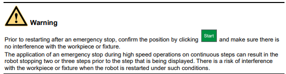
[E-STOP] Power off the robot by pressing the E-stop button of the programming pendant or control cabinet, and the robot stops immediately.
[Release] Turn the E-stop button in the direction of the arrows. Then press  and power on the servo.
Restart after Emergency Stop
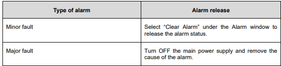
Stop by Alarm
If an alarm occurs during operation, the robot stops immediately and the Alarm window appears on the programming pendant indicating users can enter the system log interface to view the detailed alarm.
Others
Temporary Stop by Mode Change
When the playback mode is switched to the teach mode during playback, the robot stops immediately.
To restart the operation, return to the playback mode and perform a start operation.
Temporary Stop by the PAUSE Command
When the PAUSE command is executed, the robot stops operating.
To restart the operation, perform a start operation. The robot restarts from the next command.
Modifying playback speed
Users can modify the playback speed by means of the speed increase or decrease keys in the following way:
Speed can be modified during playback.
Speed can be changed experimentally, and modification can be performed when the actions are determined.
No comments to display
No comments to display