
4. Introduction to System Functions
The interaction between the robot controller and the user is performed through the programming pendant.
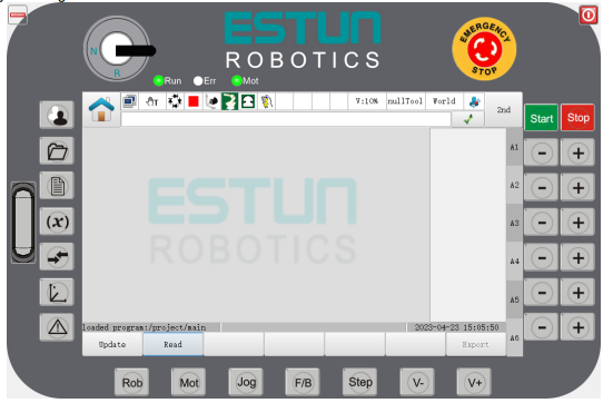
Programming pendant is an important part of the robot control system. The operator manually teaches using the programming pendant, controls the robot to produce the different poses, and records the coordinates of each pose; use the robot language to program online, realize the program playback, and enable the robot to move along the path required by the program. Programming pendant consists of the following functional component:
The programming pendant we use provides functional components including:
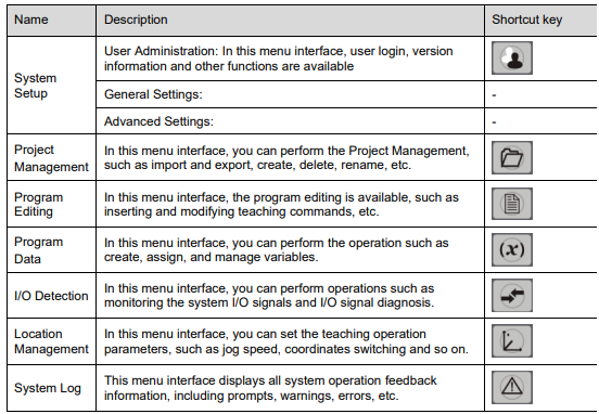
4.1 Project Management
Press  or click on "Project Management" on the main screen to enter the Project Management interface, which consists of a status bar, function keys at the bottom and function keys on the right, as shown below:
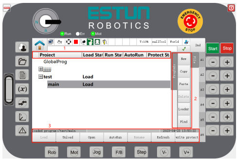
1. Status Display Bar:
Project List: Displays the project name, click on to expand all program files under the project directory.
Load Status: Displays whether the project or program is "loaded", the default display is blank, then "loaded".
Running Status: Displays whether the project or program is running, with "running", "paused" or "stopped" available under running status.
Self-trigger: Displays whether the program is set to "Self-trigger". The default display is blank, and when enabled, the display shows "Self-starting".
Write Protection: Displays whether the program is set to "Write Protection". The default display is blank, "read-only" appears when switched on.
2. Function Keys at the Bottom
Load: Loads a project or program from an existing project, allowing you to load the program directly.
Logout: Used in conjunction with Load, the button is greyed out when the file is not loaded.
Open: can only open program files. you need to load the project before opening; opening is not the same as loading, when running you will be prompted to import the program first.
Self-trigger: Automatically loads the program file set in remote mode; a pop-up window will appear if the program is not compatible with the self-trigger.
Rename: Rename the project or program name, not case sensitive.
Refresh: Refreshes the current interface.
Write Protection: Read-only program, which cannot be modified.
Turn ON: Select the desired program, click on the "Write Protection" button. After turning on "Write Protection" according to the prompts on the interface, the user cannot modify the contents of the program, as the global variables, project variables and program variables in the program cannot be changed.
Cancel: Select the program again and click on the "Cancel Write Protection" button, and user can change the program after cancel the write protection according to the prompts.
If this button is greyed out, it means that the current user does not have access to the program. This function can only be operated by "Admin" and "Factory Personnel".
3. Function keys on the right
Create: to create a new project or a new program file under an existing project;
Copy: to copy an existing project or program file and prompt for renaming of the copied project or program after clicking Paste;
Paste: used in conjunction with the copy function;
Delete: to delete a project or program that is not needed;
Admin: to import and export a project;
Find: to find a program;
Program Information: to view the status information of the selected program and add notes.
4.1.1 Creating a New Project or Program
Create a new project or a program by following the procedure below.
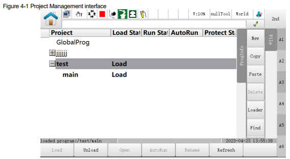
Step 1 Click  , or the “Project Management” on the main interface to enter Project Management interface, as shown in Figure 4-1. In the Project Management interface, click "Refresh" below to update the list of project.
Step 2 Select "File→Create" on the right, and the "Create a Program" dialog box will pop up, as shown in Figure 4-2.
 In other interfaces, select "File→Create" on the right to perform the operation of creating a new project.
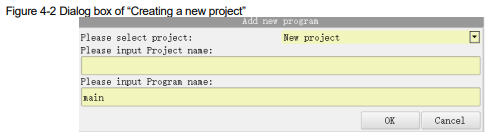
Step 3 To create a new project, select "Create a New Project" from the drop-down list on the right of "Select a Project".
If you want to create a new job in a project, select the desired project name in the drop-down list and skip to Step 5.
Or, select a desired project in the project list in advance, and then click "Create".
If there is no program in the project list, the option "Create a Project” is in default.
Step 4 Click the input box of "Please enter the project name", and enter the name of the project to be created in the soft keyboard popped up, for example, project0.
Step 5 Click the input box of "Please enter the program name", and enter the name of the program to be created in the soft keyboard popped up, for example, program0.
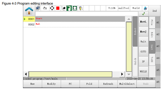
Step 6 Click "OK", a new project or program is then created. The interface jumps directly to the program editing interface, as shown in Figure 9-3.
----END
4.1.2 Deleting a New Project or Program
Delete a project or a program by following the procedure below.
Step 1 Click the project or program to be deleted in the Project Management interface, for example, project0.

1. To delete a project that has been "loaded", you need to click "Cancel" below before performing the normal delete operation.
2. To delete a program, you must ensure that the project in which the program is located is logged out before deleting.
Step 2 Click "Delete" on the right, and a prompt box will pop up, as shown in Figure 4-4.
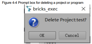
Step 3 Click "OK" to delete the project.
----END
4.1.3 Renaming a Project or Program
Rename a project or a program by following the procedure below.

1. To rename a project that has been "loaded", you need to click "Cancel" below before performing the renaming operation.
2. To rename a program, the project in which the program is located cannot be "loaded" and must be "logged off" before the program can be renamed.
Step 1 Click the project or program to be renamed in the Project Management interface, for example, project0.
Step 2 Click the "Rename" below.
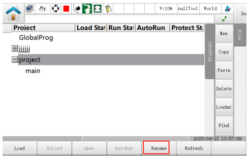
Step 3 Click "Enter a new project name", and enter the new name in the pop-up soft keyboard.
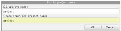
Step 4 Click "OK", and the rename operation is done.
----END
4.1.4 To copy/paste a project or program
Copy and paste a project or a program by following the procedure below.
Step 1 Click a project or program to be copied in the Project Management interface, for example, project0.
Step 2 Click "Paste".
The same program cannot be copied and pasted into different project directories.
When a program is to be copied, if the pasted path is under another project, the prompt message "Unable to copy the program to another project!" will pop up. Please click and select the correct project before proceeding.
Step 3 Click "Please enter a new project name", and enter the new project name in the soft keyboard.
Step 4 Click "OK" to finish the copy/paste operation.
----END
4.1.5 Load/Cancel a New Project or Program
In the project list, the "Loading Status" column already shows the project or program being loaded.
Only one project or program can be loaded. When another project or program is loaded, the previously loaded project or program will be automatically cancelled.
To load or log off a project or program, click the project or program you want, and then click "Load" or "Cancel".
4.1.6 Self-triggered Program
The self-trigger function can only be set for programs, not for projects. If a program is set to " selftriggered", it will be loaded automatically when the remote mode is enabled.
Step 1 Select the program that needs to be self-triggered in the project list.
Step 2 Click on the "Self-trigger" button below.
Step 3 Click on "OK" in the pop-up dialog box to complete the self-trigger operation of the program.
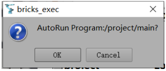
4.1.7 Write Protection
The Write Protection function can only be set for the program, not the project. If a program is "writeprotected", the user cannot make any changes to the program files or variable files in the project. This function can be cancelled manually, which guarantees the security of the program files.
Step 1 Select the program that needs to be write-protected in the project list.
Step 2 Click on the "Write Protection" button below.
Step 3 Click "Yes" in the pop-up dialog box to complete the write protection of the program.
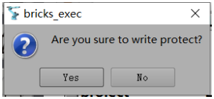
Step 4 Click on "Remove Write Protection" below and follow the pop-up box to remove the write protection from the program.
4.1.8 Administration (Project Import/Export)
Before performing the project import/export operation, the user needs to prepare a readable and writable USB flash drive, and then perform the following procedures.
Project Import: To import the project or program file in the USB flash drive to the controller.
Project Export: To export the project or program file in the controller to the USB flash drive.
The following operations are the procedures for project import, which is similar to project export.
Step 1 Insert the U disk into the USB interface of the teaching pendant.
Step 2 Click  , and enter the Project Management interface.
Step 3 Click "Manage" in the right menu to enter the interface, as shown in Figure 4-5
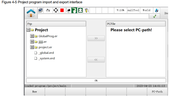
Click on "USB path" at the bottom right.
Supports the export of project and data files from the controller to a USB flash drive.
Supports importing the project and data files from the USB flash drive into the controller.
Supports the creation of a new project folder under the project root folder in the controller.
Supports deleting files and folders under the project root folder in the controller.
Supports the creation, deletion, copying, pasting, renaming and opening of folders in the USB flash drive.
Project Export
1. Click on the "USB flash drive path" at the bottom right to access the USB flash drive.
2. Select the program file to be exported from the list of "Project File" on the left.
3. Click ">>" in the middle of the interface to export the program file selected to the USB flash drive.
Project Import
1. Select the program file to be exported from the "Project File" list on the right.
2. Click on "<<" in the middle of the interface to import the selected program file to the controller.
3. If the selected file is _global.erd, then a pop up will appear asking you to check the files that will not be overwritten. The following variable types are currently available: APOS, CPOS, DAPOS, DCPOS, AERA, USERCOOR, TOOL (in line with EStunEdit).
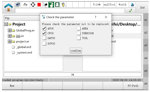
Note
When importing the _global.erd file, data types that are checked in the interface will not be replaced into the robot controller; data types that are not checked or do not exist in the interface will be removed and replaced with the _global.erd data as checked on the right hand side of the interface.
Create
1. Click "Create" below, and the project create dialog box as shown in Figure 4-6 will appear.

2. Click the input box of "Enter a new project name", and enter the name of the project to be created in the soft keyboard, for example, project0.
3. Click "OK" to produce a new project, prompting "Please reload the project". You can view the new project in the project file list in the teaching box on the left.
----END
4.1.9 Search for a Project/Program
Locate a project or program by following the guidance steps below.
Step 1 Click the "Search" button in the Project Management interface to bring up the "Search for a Program" interface, as shown in Figure 4-7.

Step 2 Enter the text you are looking for in the "Name" input box and click the "Search" button to search.
Note
On the left side of the Search screen, there are three filtering criteria including project name (checked by default), case-sensitive and all-word match checkboxes, which can be freely checked according to your needs. You can also enter some of the consecutive characters in the name to be located
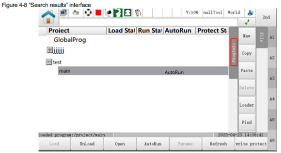
Step 3 The search result will be displayed, divided into three types: not found, one found, and multiple found. When multiple found, you can click on the "Previous" and "Next" buttons to switch the search result, and the project list will locate to the line with the search result, as shown in the figure below.
Step 4 Click "Close" to exit the Search function.
----END
4.1.10 Program Information
You can quickly view basic information about the current program or add comments.
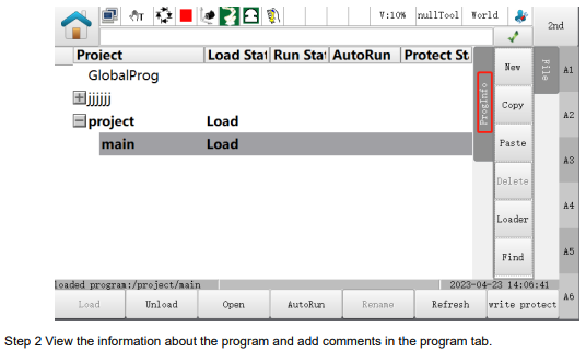
Step 1 Select the program to view and click on the "Program Information" button on the right to switch to the Program Information tab.
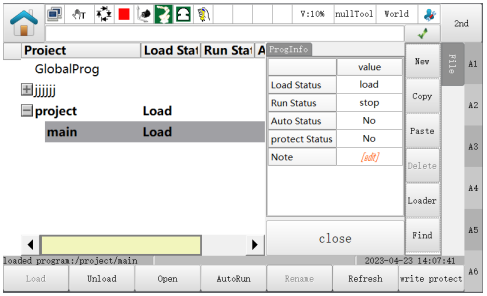
Load Status: Loaded, Not loaded, Called, /
Running Status: running, paused, stopped, parallel, execution interrupted, parallel interrupted, invoked interrupted
Self-trigger: Yes, No
Write Protection: Yes, No
Comments: red font [editable] is displayed when no comments are available, click on the comments field to fill in the comments.
The maximum length of a comment can be 35 characters.
4.2 Program editing
Press  , or click "Program Editing" on the Home interface to enter the program editing interface.
Note
⚫ You need to load the project where the program is located before editing commands.
⚫ Program editing interface entered by clicking the menu key or through the Home interface is the program being loaded. Refer to “Loading/canceling a project or program” for operation if there’s no program currently loaded.
⚫ Users may also click on the program being loaded in the Project Management interface, and then click "Open" at the bottom to enter the Program Editing interface. You can edit programs that have not been loaded under the project being loaded using this manner
4.2.1 Adding a New Command
Create a new command by following the procedure below.
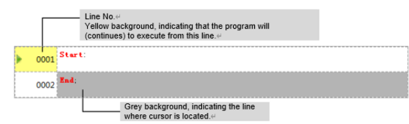
Step 1 Enter the program editing interface as shown in Figure 4-9, which is an interface description for an empty program.
Move the cursor to the line where "End" is located when inserting the first command in the new program.
Figure 4-9 Interface description for an empty program

Step 2 Click "Create" at the interface bottom to enter the command selection interface, as shown in Figure 4-10.
Figure 4-10 Command selection interface
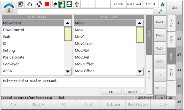
Step 3 Select "Command Class", and then select the command to be used on the right.
For example, if you need to create a new motion command MovJ, select "Motion Command→ MovJ".
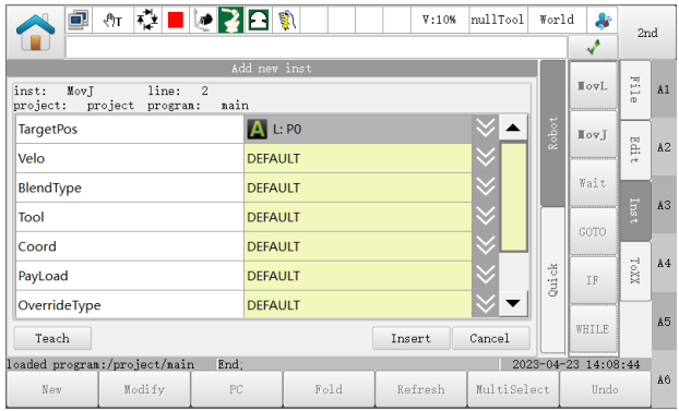
Step 4 Click "OK" and enter the "Create Command" dialog box, where you can edit the command parameters you want to insert. Figure 4-11 shows the parameter editing dialog box of MovJ.
Figure 4-11 Edit the parameters of the MovJ command
Note
Parameter may be blank for some commands.
Step 5 Edit the parameters of the command based on actual requirements.
Following methods may be used for edition of different parameters:
⚫ Click the input box of the parameter, and enter the correct value in the soft keyboard.
⚫ Click the drop-down arrow behind the input box, and select the desired parameter from the drop down list.
⚫ For the parameter denoting the position, click "Teach" if you want to select the current position as the parameter value.
Step 6 Click "Insert" after the parameter is edited.
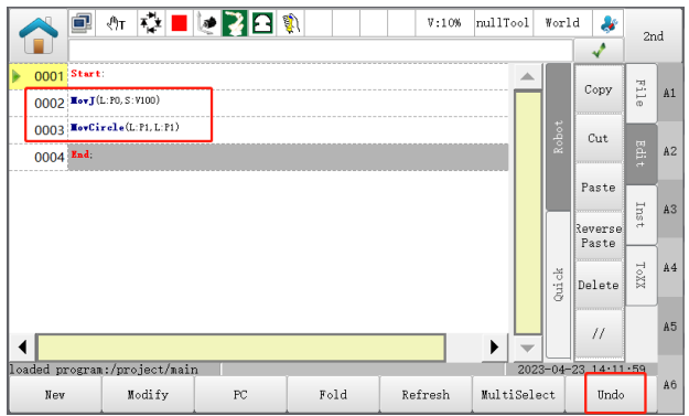
A MovJ command is successfully inserted if the interface returns to the command editing interface, as shown in Figure 4-12.
Figure 4-12 Successful insertion of MovJ command

Step 7 Continue to add commands using the method described above.
Step 8 After checking and confirming that all program, you can return to the home interface for other operations.
----END
4.2.2 Cancelling a Command
In case of an incorrect operation while editing the program, and you want to cancel he new or modified command, click "Cancel" in the command editing interface to withdraw and return to the previous step, as shown in Figure 4-13.
Figure 4-13Withdraw a command
Note
Up to 64 steps of commands can be cancelled.
If the program is cancelled, loaded or reopened, this operation cannot be performed.
4.2.3 Other operations
Modifying Command Rapidly
To quickly modify a command, refer to the following steps:
Step 1 Click on the command to be modified
Step 2 In the "Quick Teach" pop-up box on the right, select the parameter to be modified, as shown in Figure 4- 14.
Figure 4-14 Modify the parameters of a command rapidly
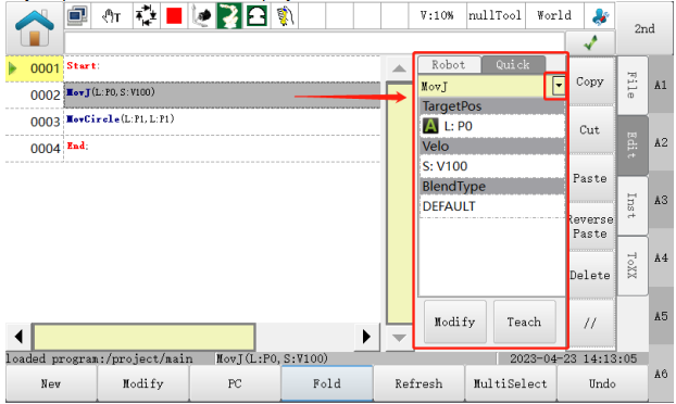
1. Click on the drop-down box on the right to quickly switch between MovJ and MovL commands. Taking MovJ to MovL as an example, proceed as follows: select the MovJ command you need to switch to
2. Click on the drop-down menu in the "Quick Teach" interface on the right, select the MovJ command that needs to be switched to MovL and click on "Yes" in the pop-up box "Whether to switch MovJ to MovL".
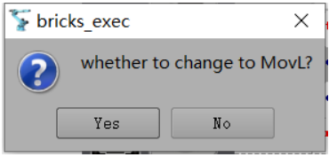
3. Click on the "Modify" button on the "Quick Teach" screen to quickly switch between MovJ and MovL commands.
Note
- When switching between MovL and MovJ quickly, the switching is successful even if the "Rate Type" is not "DEFAULT".
- If you do not click on the "Modify" button on the "Quick Teach" screen, the quick switch cannot be done.
- Quick teaching is not supported by MovJsearch/MovLsearch.
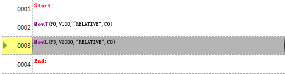
Step 3 To specify the program to start execution from a command, click the command to be executed directly, and then click "PC" below, the pointer will change to the command, as shown in Figure 4-15. The, the command executing position has been changed to Line 0003.
Figure 4-15 Start position of change command execution
----END
Tips
Users can click on the "Command" on the right to create a frequently used command.
In addition, users can also click "Edit" on the right to perform the following operations on this interface:
⚫ Copy: Click to select the command to be copied, and then click "Copy". Cross-program "Copy" is supported.
⚫ Cut: Click to select the command to be cut, and then click "Cut". Cross-program "Cut" is supported.
⚫ Paste: Click to select the position of the command to be pasted, and then click "Paste". Cross-program "Paste" is supported.
⚫ Reverse Paste: Click to select the location of the command to be pasted, then click on "Reverse Paste" to paste the selected multiple lines of commands into the location in the reverse order. Cross-program "Reverse Paste" is supported.
⚫ Delete: Click to select the command to be deleted, and then click "Delete".
⚫ //: Click to select the command to be annotated, and then click "//".
⚫ ToPC: Click "ToPC" to return the program editing interface to the line where the pointer is located.
⚫ Cross-program refers to different programs under the same project.
⚫ The command supports cross-program copy, cut, paste and reverse paste operations, but not cross-engineering operations.
⚫ The pasted command distinguishes between variable types. If the command contains program variables and the currently loaded program does not have the same program variables, the execution process will report an error; if the currently loaded program has variables with the same name, the execution will be normal and the value of the variables will be based on the one under the current program. Global variables and project variables are not affected by this.
⚫ If you paste a command containing a program variable, you can modify it if there is no corresponding variable in the current loaded program, and the command can be executed normally after creating a new variable.
⚫ For a detailed description of each instruction, please refer to Chapter 6.
One Point Reach by Command Point
In manual mode, the user can locate the target point manually by clicking "Quick Reach" → "Location Point" on the right side of the program page, as shown in Figure 4-16.
Figure 4-16 Reach the location point quickly
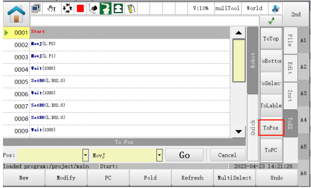
Select the target "point" and the running command "MovJ" or "MovL" in the floating options, and then press "Go", the TCP will continue to run to the target point; release "Go" to stop the movement of the TCP, as shown in Figure 4-17.
Figure 4-17 Select the target point and run
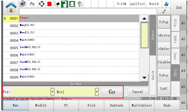
Please select the command line that specifies the target point, the "point" in the floating option will automatically show the variable of the target point.
When multiple points appear in the command line, you can select the desired target "point" in the drop-down list.
Only "MovJ" and "MovL" are optional for the command operation when running to the target point.
If the coordinate system parameters such as tool and usercoord are included in the command, switch the coordinate system to these set coordinates and perform point motion to avoid problems related to collision arising from execution errors.
Locating Program Line Rapidly
User can click "Quick Reach" on the right side in the program page, and select the position to be quickly located, such as "Top", "Bottom", "Select Line" or "Specify Line", as shown in Figure 4-18.
Figure 4-18 Locating program rapidly
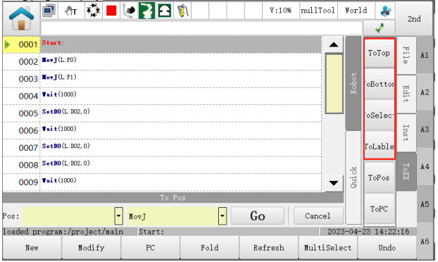
Click "Top", and the display of the program line will be located to the "Start" line.
Click "Bottom", and the display of the program line will be located to the "End" line.
Click "Select Line", and the display of the program line will be located to the position of the currently selected line.
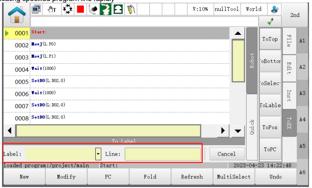
Click "specified line"; select the "label" or "line number" to be located in the options appeared, and the display of the program line will be located to the designated one.
Figure 4-19 Locating specified program line rapidly
Motion Execution Pointer
The motion execution pointer is used to point to the currently executed motion segment or the motion segment in which the robot is currently resting.
The motion execution pointer has been added to the program editing screen and is still displayed to the left of the selected row. It can point to the same motion command as the execution pointer.

According to the above example program:
1. When execution reaches line 2, both the normal execution pointer and the motion pointer are displayed on that line;
2. When the execution pointer reaches the SetDO command on line 4, the execution pointer will be displayed on that line, but the motion pointer will stop on line 3 as the robot stops at point P1 of MovL on line 3.
3. The motion execution pointer will jump to this line of display until the system executes to line 7 at MovL (P2).
4.3 Program data
Press  or click "Program Data" on the Home interface to enter the Program Data interface.
Click "Refresh" below to update the variable list in this interface.
Program data (variables) is of four ranges: System, Global, Project and Program.
⚫ System (S): The variables as initially defined by the system.
⚫ Global (G): The variables that can be used by all projects or programs.
⚫ Project (P): The variables that can be used by programs in the same project.
⚫ Program (L): The variables that can only be used in the current program.
Different domains support different types of variable. For details, please refer to "Chapter 5 Introduction to Variables".
4.3.1 Creating Variable
Create a new variable by following the commands below.
Step 1 Enter the program data interface, as shown in Figure 4-20.
Figure 4-20 Program data interface
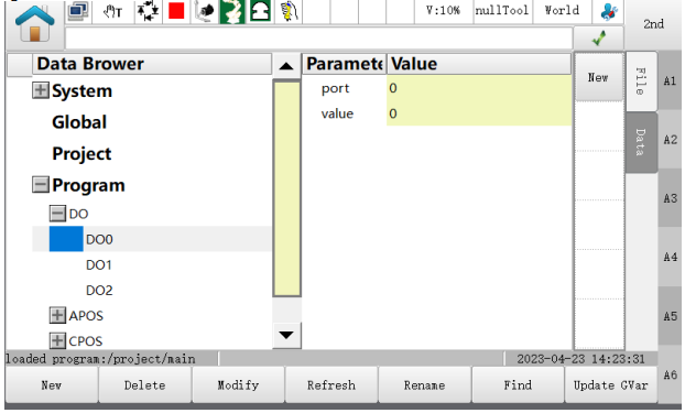
Step 2 Click on the range to be created, such as "Global".
Step 3 Click "Create" and set the relevant parameters in the pop-up dialog box, as shown in Figure 4 21.
Figure 4-21 Creating a new variable
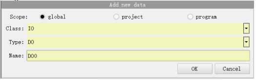
Step 4 Confirm or select the "Domain" (range) to which the variable to be created belongs.
Step 5 Set the category of the variable to be created. Table 4-1 lists all the categories and types.
Table 4-1 Categories of variables
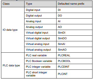
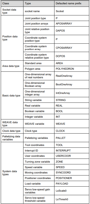

Step 6 Click the "Name" input box, and enter the name you want to define in the pop-up soft keyboard.
Note
The following "names" are reserved by the system and contain mainly the names of basic functions, commands and variables, as well as specific names, etc. Users may not create variables with the same name.
Basic functions:
and, break, do, else, elseif, end, false, for, function, if, in, local, nil, not, or, repeat, return, then, true, until, while, assert, tostring, tonumber, rawget, xpcall, ipairs, print, pcall, rawset, error, loadfile, rawequal, load, pairs, require, collectgarbage, dofile, next, select, type, getmetatable, goto, setmetatable, debug, log, max, acos, huge, pi, cos, deg, tan, random, randomseed, ceil, floor, rad, abs, sqrt, modf, asin, min, fmod, log, atan, exp, sin, coroutine, math, io, os, package, string, table, byte, find, find2, char, gsub, len, sub, lower, trim, upper
Variable types:
BOOL, INT, REAL, STRING, BOOLONEARRAY, INTONEARRAY, REALONEARRAY, APOS, CPOS, TOOL, USERCOOR, AI, AO, DI, DO, SimAI, SimAO, SimDI, SimDO, RET, AREA, POLYHEDRON, CLOCK, PLCREAL, SOCKET, PALLET, WEAVE, SPEED, ZONE, PAYLOAD, EXTTCP, POSITIONER, SYNCOORD, LsScale, LsThresh, PLCREAL, PLCBOOL, PLCINT, PLCDOMNT, APOSARRARY, CPOSARRARY, INTERRUPT
Command names:
MovJ, MovL, MovC, MovCircle, MovJRel, MovLRel, MovLOffset, MovJSearch, MovLSearch, MovLW, MovCW, MovCircleW, MovH, MovArch, OnDistance, OnParameter, LABEL, GOTO, ENDIF, THEN, IF, THEN, ELSIF, ELSE, ENDWHILE, DO, WHILE, CALL, RUN, KILL, RETURN, /*...*/, ...=..., SetDO, SetAO, SetSimDO, SetSimAO, WaitDI, WaitDI8421, WaitAI, WaitSimDI, WaitSimDI8421, WaitSimAI, PulseOut, PulseSimOut, GetDI8421, GetSimDI8421, SetDO8421, SetSimDO8421, GetSimDIToVar, SetSimDOByVar, GetSimAIToVar, SetSimAOByVar, SetDIEdge, SetSimDIEdge, Wait, WaitFinish, WaitCondition, GetCurAPos, GetCurCPos, APosToCPos, CPosToAPos, CPosToCPos, ToolOffset, UserOffset, WaitWObj, MovLSync, MovJSyncQuit, MovLSyncQuit, SetTargetPos, SetSyncoord, SynCToUserC, WaitConvDis, SimConveyorOn, SimConveyorOff, ReceiveWObj, ResetWObjBuf, BitAnd, BitNeg, BitOr, BitXOr, BitLSH, BitRSH, CLKStart, CLKStop, CLKRead, CLKReset, AreaActivate, AreaDeactivate, PolyhedronAreaActivate, PolyhedronAreaDeactivate, TrigCam, WaitFinishCAM, GetCamPos, SendMessage, Tracking, PalletReset, PalletToPut, PalletFromPut, PalletToGet, PalletFromGet, SetMatrix, GetMatrix, SocketCreate, SocketClose, SocketSendStr, SocketSendReal, SocketSendInt, SocketReadReal, SocketReadInt, SocketReadStr, GetModConState, ReadModbusReg, WriteModbusReg, SoftFloatStart, SoftFloatStop, IToStr, RToStr, StrToI, StrToR, APosToStr, CPosToStr, TranStrToInt, TranStrToReal, TranStrToApos, TranStrToCpos, MA_ELF_START, MA_ELF_STOP, SetTool, SetCoord, SetExternalTCP, SetPositioner, SetPayload, SetJointDyn, SetCartDyn, SetBlendParam, SetOverRide, SetSingularPass, SetColliEnable, SetAxisColliParam, GetCurOverRide, Hand, CalcTool, CalcCoord, SetRtToErr, SetRtInfo, SetRtWarning, Stop, RefRobotAxis, SetMotionMode, AutoGainEnable, AutoGainDisable, SetAxisVibraBLevel, SetRestorePC
Specific names:
POSCFG, PLACEOPTIO
Step 7 Click “OK” after confirming that the variable to be created is set correctly.
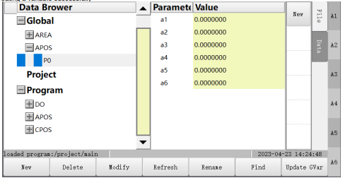
The interface will return to the list of variables and display the created variable data. Figure 4-22 shows that a global position variable P0 has been added.
Figure 4-22 Creating a variable successfully
----END
4.3.2 Standard area variables
Create a new standard area variable by following the steps below.
Step 1 Enter the program data interface and click "Create".
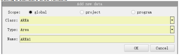
Step 2 Select "Class" as "Area Data Type" and "Type" as "Standard Area" from the pop-up dialog box, and enter the "Name", for example, AREA1, as shown in Figure 4-23.
Figure 4-23 Creating a standard area variable
Step 3 Click “OK” after settings of the area variables to be created are confirmed to be correct.
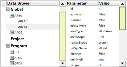
Step 4 The interface will return to the list of variables and display the created variable data. Figure 4 24 shows that a global area variable AREA1 has been created successfully
Figure 4-24 Creating a standard area variable successfully
----END
4.3.3 Polygon area variables
Create a new polyhedron area variable by following the steps below.
Step 1 Enter the program data interface and click "Create".
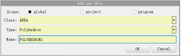
Step 2 Select "Class" as "Area Data Type" and "Type" as "Polyhedron" from the pop-up dialog box, and enter the "Name", for example, POLYHEDRON1, as shown in Figure 4-25.
Figure 4-25 Creating a polyhedron area variable
Step 3 Click “OK” after settings of the polyhedron area variables to be created are confirmed to be correct.
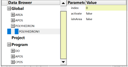
Step 4 The interface will return to the list of variables and display the created variable data. Figure 4 26 shows that a global polyhedron area variable POLYHEDRON1 has been created successfully.
Figure 4-26 Creating a polyhedron area variable successfully
----END
4.3.4 Tool Coordinates Variables
Create a tool coordinates variable by following the procedure below.
Step 1 Enter the program data interface and click "Create".
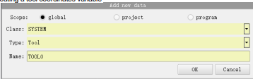
Step 2 Select "Class" as "System Data Type", and "Type" as "Tool Coordinates" in the pop-up dialog box, and enter the "Name" (TOOL0), as shown in Figure 4-27.
Figure 4-27 Creating a tool coordinates variable
Step 3 Click “OK” after settings of the tool coordinates variable to be created are confirmed to be correct.
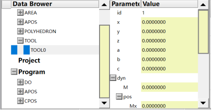
Step 4 The interface will return to the list of variables and display the created variable data. Figure 4-28 shows that a global variable TOOL0 for tool coordinates has been created successfully.
Figure 4-28 Creating a tool coordinates variable for successfully
----END
4.3.5 User Coordinates Variables
Create a user coordinates variable by following the procedure below.
Step 1 Enter the program data interface and click "Create".
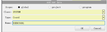
Step 2 Select "Class" as "System Data Type", and "Type" as "User Coordinates" in the pop-up dialog box, and enter the "Name" (USERCOOR1), as shown in Figure 4-29.
Figure 4-29 Creating a user coordinates variable
Step 3 Click “OK” after settings of the user coordinates variable to be created are confirmed to be correct.
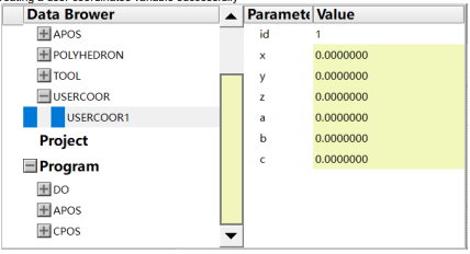
Step 4 The interface will return to the list of variables and display the created variable data. Figure 4 30 shows that a global user coordinates variable USERCOOR1 has been created successfully.
Figure 4-30 Creating a user coordinates variable successfully
----END
4.3.6 External Tool Coordinates Variables
Create an external Tool Coordinates variable by following the procedure below.
Step 1 Enter the program data interface and click "Create".
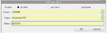
Step 2 Select "Class" as "System Data Type", and "Type" as "External TCP Coordinates" in the pop-up dialog box, and enter the "Name" (e.g. EXTTCP1), as shown in Figure 4-31.
Figure 4-31 Creating an external tool coordinates variable
Step 3 Click “OK” after settings of the external tool coordinates variable to be created are confirmed to be correct.
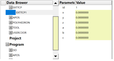
Step 4 The interface will return to the list of variables and display the created variable data. Figure 4 32 shows that a global external tool coordinates variable EXTTCP1 has been created successfully.
Figure 4-32 Creating an external tool coordinates variable successfully
 ----END
4.3.7 Other operations
Modifying Variable Value
Modify the value of a variable by following the procedure below:
Step 1 Select the variable to be modified, and “Parameters” and “value” of the variable will appear on the right side of the interface.
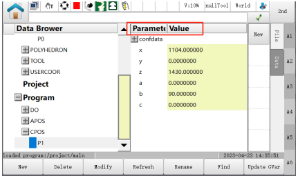
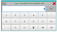
Step 2 Click the parameter value to be modified and re-enter the correct value in the pop-up soft keyboard (note the range of parameter values on the soft keyboard).
Step 3 For some special variables (variables that cannot be entered into edit mode by clicking on "value"), click "Modify", and the interface will display the modification interface to assist operation.
----END
Deleting a Variable
Step 4 Select the variable to be deleted, click "Delete", then the prompt box shown in Figure 4-33 will pop up.
Figure 4-33 Prompt box of “Deleting Variable”
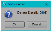
Step 5 Click "OK" to delete the variable.
Renaming a Variable
Step 1 Select the variable to be renamed, the "Change Variable Name" interface will pop up by clicking "Rename", as shown in Figure 4-34.
Figure 4-34 Renaming a variable
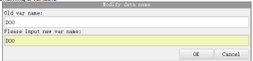
Step 2 Click the input box of "New variable name", and type the desired name in the pop-up soft keyboard.
Step 3 Then click "OK". The variable renaming is done.
Searching Variable
Step 1 Click "Search" in the "List of Variable" page, and enter the "Name" of the variable you want to search in the floated option, as shown in Figure 4-35.
Figure 4-35 Searching variable
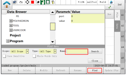
Step 2 You can find the desired variable precisely by selecting the "Domain" or "Type" you want to search.
Step 3 Click on "Search".
Step 4 When a matching name is searched, multiple results appear. You can select by clicking "Previous" or "Next".
4.4 IO detection
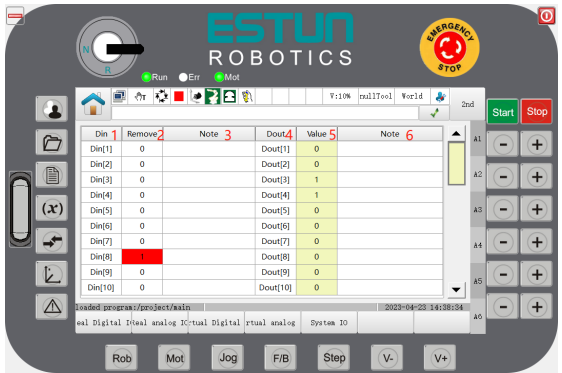
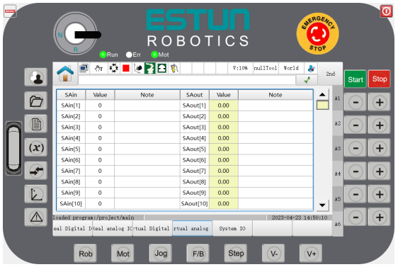
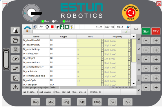
Press  or click "IO Detection" on the Home interface to enter the IO Detection interface, which consists of five tabs: Physical Digital IO, Physical Analog IO, Virtual Digital IO, Virtual Analog IO, and System IO. The default tab is the physical digital IO interface, as shown in Figure 4-36.
Figure 4-36 IO detection interface
Modify the values of digital IOs:
If you need to set up the physical digital IO and virtual digital IO for simulation, please refer to the following:
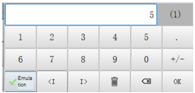
Step 1 To modify the value: Click on the value of the digital IO to be modified and the corresponding 01 keyboard will pop up, as shown below:
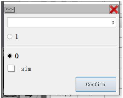
Step 2 Select 0 or 1 and check the "Emulation" checkbox, then click "OK", as shown below, and the value of the corresponding port will become the set value and turn red, which indicates successful modification.
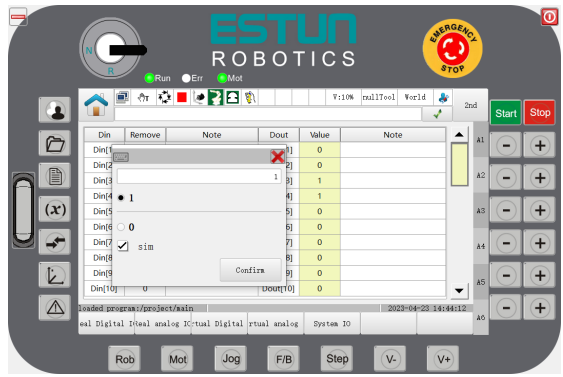
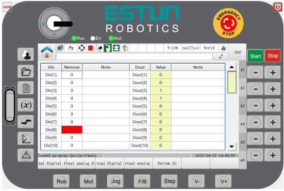
Step 3 To release the emulated value of one of the ports, click on the digital IO that needs to be modified, check "Emulate" in the corresponding pop-up box, and click "OK".
Step 4 Click on "Release Emulation" above and confirm the release according to the interface prompt to restore the port value of the physical IO to its initial state.
Modify the value of analog IO:
For physical analog IO and virtual analog IO, please refer to the following if you need to set up emulation:
Step 1 Click the value of analog IO to pop up the corresponding keyboard, as shown below
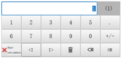
Step 2 Input the value of the analog IO you want to set, click “Non-simulation”, and then click "OK" button. As shown in the figure below, the value of the corresponding port will be changed to the set value and become red, which means the modification is successful.
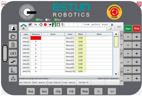
Step 3 If you want to release the emulation value of one of the ports, click the IO emulation that you want to modify, click " Emulation " in the corresponding pop-up box, and then click "OK" button.
Step 4 Click on "Release Emulation" above and confirm the release according to the interface prompt, while the virtual IO will only change the emulation state, but the modified port value will remain unchanged.
Physical IO
Click on "Physical Digital IO" below to switch to the "Physical Digital IO" screen:
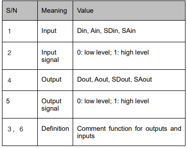
Figure 4-37 Physical digital IO interface
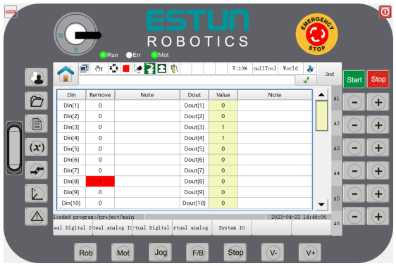
The parameters are described below:
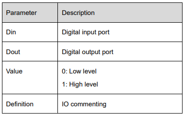
The system Din/Dout ports are described below:
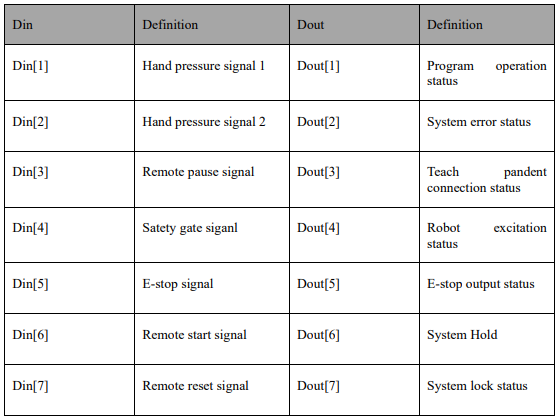
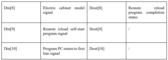
Physical Simulation IO
Click on the "Physical Simulation IO" button below to switch to the "Physical Simulation IO" tab.
Figure 4-38 Physical simulation IO interface
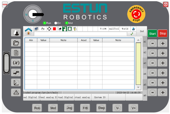
The parameters are described below:
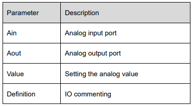
Virtual Digital IO
Figure 4-39 Virtual digital IO interface
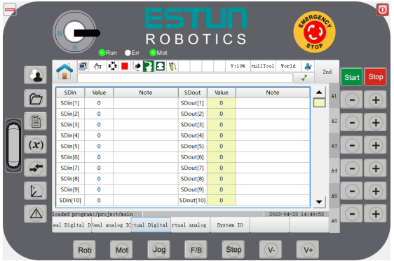
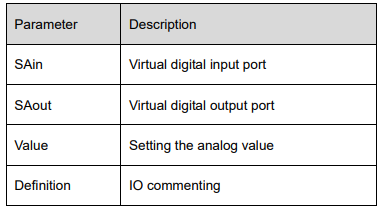
The parameters are described below:
Virtual Analog IO
Figure 4-40 Virtual simulation IO interface
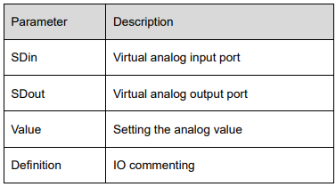
System IO
Clicking the “System IO” key and entering the password in the pop-up dialog box, then you can enter the system IO interface. System IO is not modifiable by default. The System IO interface is shown in Figure 4- 41.
Figure 4-41 System IO detection interface
4.5 Location management
In JOG mode, it is possible to run multiple axes by jogging. The robot performs simultaneous movements of multiple axes with a speed limit of up to the national standard (250 mm/s).
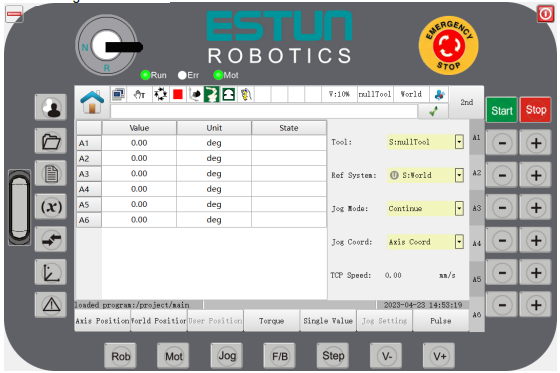
Click  , or the "Location Management" in the "Jog Management" plugin group in Home interface to enter the location management interface, as shown in Figure 4-42.
Figure 4-42 Location management interface
Joint Coordinates
Click "Joint Coordinates", and the current joint position information of the robot (A1, A2, A3, A4, A5, A6) will appear.
World Coordinates
Click "World Coordinates", the position information (X, Y, Z, A, B, C) of the robot TCP in the World Coordinates will appear.
User Coordinates
If the “Reference Coordinates” is set to “G: USERCOOR”, clicking “User Coordinates”, the position information of the robot TCP in the User Coordinates (RX, RY, RZ, RA, RB, RC) will appear.
External Tool Coordinates
If the “Reference Coordinates” is set to “G: EXTTCP”, clicking “External Tool Coordinates”, the position information of the robot TCP in the External Tool Coordinates (EX, EY, EZ, EA, EB, EC) will appear.
Positioner Coordinates
If the “Reference Coordinates” is set to “G: POSITIONER””, clicking “Positioner Coordinates”, the position information of the robot TCP in the Positioner Coordinates (PX, PY, PZ, PA, PB, PC) will appear.
Torque
Clicking "Torque", the rated torque value (percentage) of each joint motor of the robot will appear.
Single-turn Value
Clicking "Single-turn Value", the left side of the interface displays the set single-turn value of each axis (set by clicking the right position), and the right side displays the actual single-turn value of each axis.
Inching Setting
If "Jog Mode" is set to " Inching ", click " Inching Setting", the inching parameters of each axis of the robot will appear. To modify the jogging parameters, just click the parameter value input box and enter the value to be modified in the pop-up soft keyboard.
Users can modify the "Jog Coordinates" to the coordinate system requiring jog operation, or press the  key on the programming pendant to switch the coordinates requiring jog operation.
Homing
When the robot is in servo excitation state, click "Homing" and enter the correct administrator password in the pop-up dialog box. After that, a prompt message will pop up on the interface, as shown in Figure 4-43
Figure 4-43 Homing interface
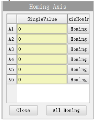
Single-axis Homing: Click on the "Homing" button after pressing the corresponding axis to perform a single-axis homing operation;
Integral Homing: Click on the "Integral Homing" button to perform a homing operation on all axes.
Note
Single-axis homing or commanded homing is recommended. Integral Homing may result in loss of robot zero accuracy.
4.6 System Log
Press  or click "Log Management" on the Home interface to enter the system log interface. The
System Log interface consists of three main tabs: Alarm, Log and Help.
4.6.1 Alarm
The alarm page is divided into two sections: "Current Alarm" and "Historical Alarm".
Current Alarm
After entering the "System Log" interface, click the "Alarm" button to switch to the alarm interface; if there is an alarm that needs to be cleared, the current alarm interface will be displayed first.
Figure 4-44 Current alarm interface
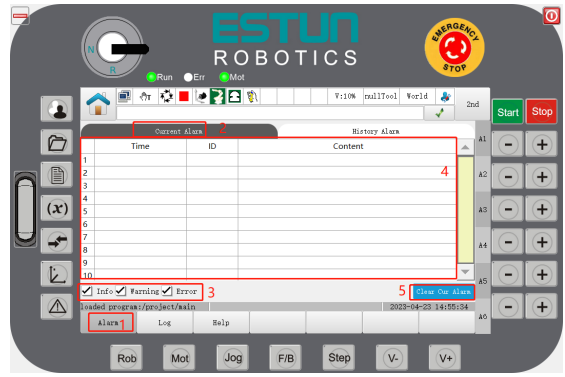
1: Click on the Alarm button to enter the alarm page 2: Current Alarm button: click on it to enter the "Current Alarm" tab to view the currently generated alarms.
4: In the alarm display page, you can find the alarm generation time, alarm number and content. Click on the "Content" corresponding to the alarm to display the "Details" of the current alarm in a pop-up window, i.e., phenomenon, cause and solution.
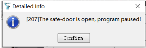
5: Clear Current Alarm button. If there is a current alarm, click on this button to clear the current alarm to enable the program to run properly. Its function is the same as the  button to the right of the alarm bar. Users may click on the
 to clear the alarm.
Historical Alarm
Click on "Historical Alarm" on the "Alarm Page" to access the "Historical Alarm" page, where you can view the history of generated alarms.
Figure 4-45 Historical alarm interface
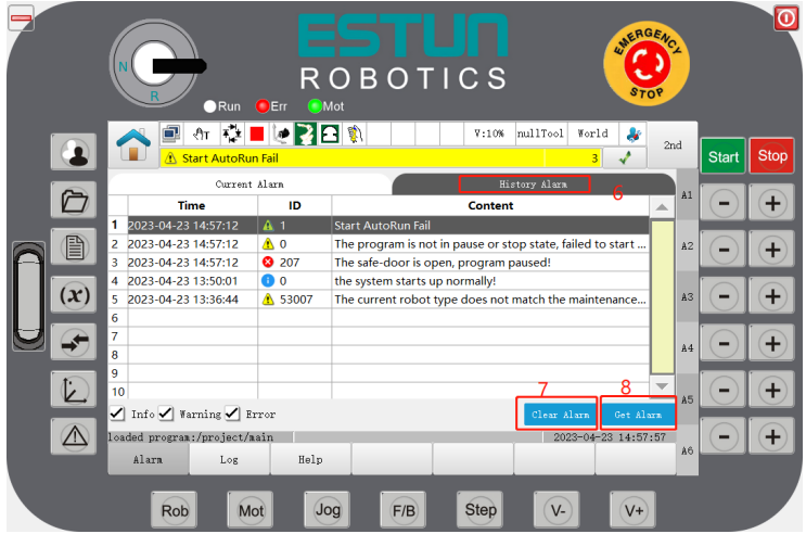
6: Historical Alarm Button: Click to switch to the "Historical Alarm" page, the interface will display the alarm information occurred since the current start-up.
7: Clear Historical Alarm: Clear all alarm information.
8: Get Historical Alarm: Synchronize all the historical alarms of the controller and update the interface of historical alarms.
4.6.2 Log
There are three ways to view and export system logs:
Home>System Log>Log
Home>General Settings>System Diagnostics
Home>Advanced Settings>Local Settings>Close Teach Pendant>ESTool
Log
Click on the "Log" button in the "System Log" interface to switch to the logging interface.
Figure 4-46 Log interface
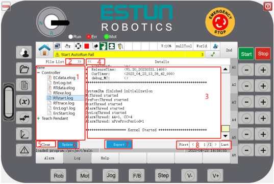
1: List of log files, showing the names of the log files. It is divided into the controller side and the teach pendant side.
2: Expandable file list, showing the file size.
3: Display interface, which reads and displays the contents of the corresponding log files.
4: Expandable and extended display is available.
5: Clear cache: Clears the local cache of the controller log files on the teach pendant.
6: Update: Updates the controller and kernel log files and refreshes the log file list.
7: Export: Pops up a USB flash drive directory browser window (shown in 4-20 below) and selects the path to the folder to be exported.
8: Page Turn Button: Enter a page number to turn the page.
Figure 4-47 File management interface
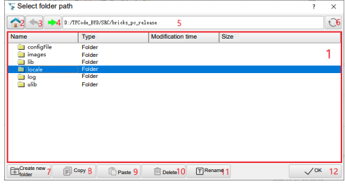
The file management interface, which pops up and displays the path of the export for the user to choose when performing the USB export:
1: Display Interface: Shows file details, i.e. name, type, modification time, size.
2: Shortcut Button: Click to return to the root directory.
3: Back Button: Click to return to the previous directory.
4: Display the contents of the selected folder.
5: Display to current path.
6: Refresh: Refresh the directory display.
7: Creat New Folder: Creates a new folder under the current folder.
8: Copy: Copies the selected file or folder.
9: Paste: Pastes the copied file or folder into the target path.
10: Delete: Deletes the selected file or folder.
11: Rename: Renames the selected file or folder.
12: OK: Confirm the path of the currently selected folder.
System Diagnosis
Clicking "System Diagnosis" in the general setting interface, the system diagnosis interface will appear, as shown in Figure 4-48.
Figure 4-48 System diagnosis interface
Clicking "Update Log", the system will then enter the diagnostic mode, and produce a report after a while.
Clicking "ViewLog", the report of the most recent system diagnosis will appear. The log files of the diagnosis report include ERC.log (controller running log), ErrLog.txt (controller running fault log), RTstart.elog (controller startup log), etc.
To export the diagnosis log file, user needs to prepare a U-disk, insert it into the USB port of the programming pendant, then click "Export Log".
All log files (controller logs and programming pendant logs) will be exported to the root directory of the USB flash drive.
Start ESTool
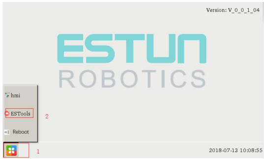
When the programming pendant is connected and the user type has been switched to "Administrator", click the local settings in the System Home/Advanced Settings, and click "Turn off the teach pendant" in the local settings power management, as shown in Figure 4-49. Then, start ESTool to enter the maintenance mode of the teach pendant (Figure 4-50), and start ESTool by clicking keys in order.
Figure 4-49 Turning off the teach pendant
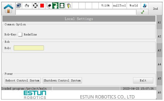
Figure 4-50 Starting ESTool
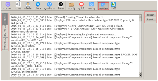
The system log files currently are available for viewing and exporting include ERC.log (controller running log), RTstart.log (controller startup log), and RTdata.elog (controller running data log).
After the ESTool is started, click logView; select the desired system log on the left side of the interface, and click “Refresh” to view the log information, as shown in Figure 4-51.
To export the system log file, insert the U-disk into the USB interface of the programming pendant, select the log file to be exported on the left side of the interface, click “Refresh” and “Export”.
Figure 4-51 ESTool view system log interface
4.6.3 Help
Click on the "Help" button in the "System Log" screen to switch to the help interface.
Figure 4-52 Help interface
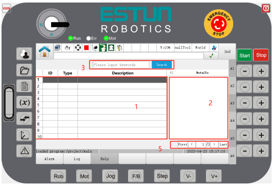
1: Display Area: Displays the parsed cases of the help file, e.g.: serial number, type, description.
2: Details Display: Displays the details of the selected case.
3: Search Box: Enter keywords and the system will filter the search by the information in the short description and details.
4: Checkboxes: Filter the display according to the type of help.
5: Page Turn button: Enter the page number to turn the page.
4.7 System settings
4.7.1 User management
Click "User Login" on the Home interface and enter the corresponding interface, as shown in Figure 4 53.
Figure 4-53 User management interface
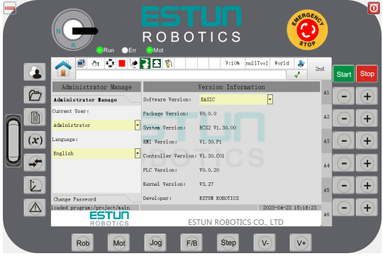
Current User
1. There are four user roles: "Administrator", "Programmer", "Operator" and "Factory Personnel", and by default the login user role is "Operator".
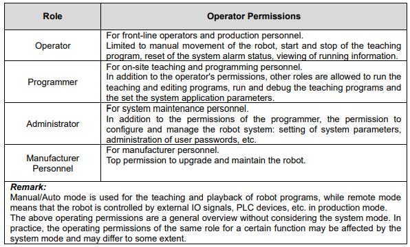
2. Different user roles have different operation permissions and the level of detail of the version information they can view also differs. The level of permissions: "Manufacturer > Administrator > Programmer > Operator" can be found in the Permission Assignment Table of Programming Pendant.
3. To switch between users: click on the drop-down list and select the required user role. To switch between some user roles, you need to enter a password.
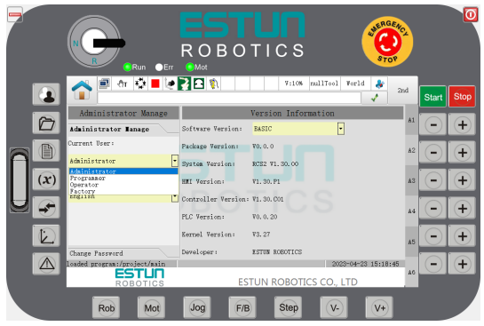
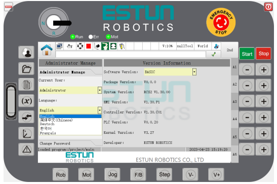
Language
The default language is "Simplified Chinese". Users can choose to switch to another system language from the drop-down menu. The switched language will take effect after a system restart.
Figure 4-54 Switching language interface
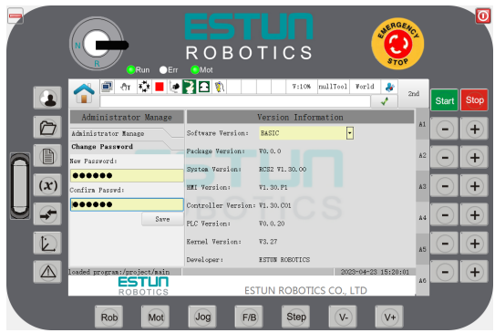
Change Password
Users can click on the "Change Password" button, switch to the "Change Password" tab, enter the "New Password" and "Confirm New Password" (you need to enter the same password twice) and click on the "Save" button to change the password of the current login user.
Figure 4-55 Change password
4.7.2 General Settings
Note
1. This chapter introduces the "Basic Settings" function in the "General Settings" section, other functions such as "Collision Detection", "Vibration Suppression", "Vision Settings", "Servo Management", "Slave Configuration", etc. are detailed in Chapter 7.
2. The functions in the "General Settings" interface are only available for the "Programmer" and "Administrator" user types. To use them, please first switch between users in "Home > User Login".
Basic Settings
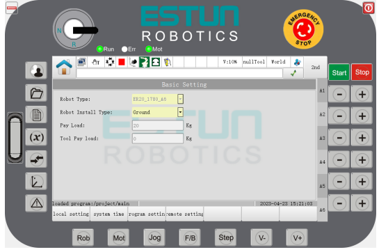
Using the Basic Settings, you can complete some basic settings for the operating software, such as system time, program settings, remote settings and other basic operations.
Step 1 Click "General Settings" on the Home screen to enter the General Settings interface, as shown in Figure 4- 56.
Figure 4-56 Interface of General Settings
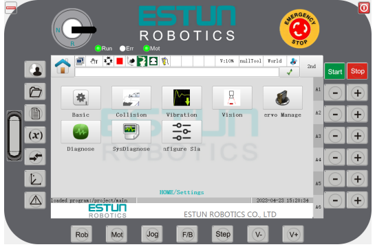
Step 2 Click on "Basic Settings" to enter the "Basic Settings" interface, as shown in Figure 4-57. Set the corresponding parameters to suit the actual situation.
Figure 4-57 Basic Settings
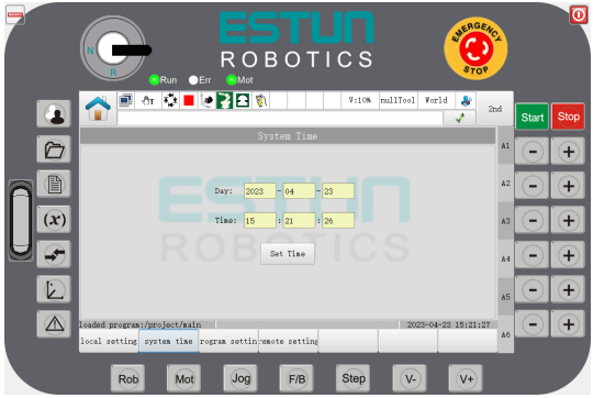
Step 3 Click on "System Time" to enter the "System Time" settings tab and set the "Date" or "Time" according to your needs. ". After setting, click on the "Set Time" button, the control system and the teach pendant will restart automatically, and the system time setting will take effect after the restart is finished.
Figure 4-58 Basic Settings - System Time
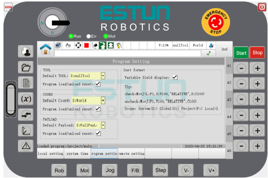
Step 4 Click on "Program Settings" to enter the "Program Settings" tab and set the appropriate parameters according to your needs.
Figure 4-59 Basic Settings - Program Settings
⚫ Tool
- Default Tool: Selects the type of tool that is loaded by default on boot. Default value: nullTool.
- Reset on program load/logout: By checking the box, the tool type will be the default after program load/logout; by unchecking the box, the tool type will be the same after program load/logout as the value set before reset.
⚫ Coordinates
- Default Coordinates: Selects the type of coordinate system that is loaded by default on boot. Default value: World.
- Reset on program load/logout: By checking the box, the type of coordinates will be the default value after reset; by unchecking the box, the type of coordinates will be the same after program load/logout as the value set before program load/logout.
⚫ Pay Load
- Default Load Inertia: Selects the load inertia variable that is loaded by default on boot. Default value: FullPayload.
- Reset on program load/logout: By checking, the load inertia type will be the default after program load/logout; by unchecking, the type of coordinates after program load/logout will be the same as the value set before reset.
⚫ Command Format
Enable the scope display of command parameters: set to distinguish between system variables, global variables, project variables and program variables in the program.
S: System variable; G: Global variable; P: Program variable; L: Program variable.
Example: For the program variable in a program, check to display MovJ (L: P1, S: V100, "RELATIVE", S: C100); uncheck to display MovJ (P1, V100, C100).
Enable for reset on program load/logout, and support for power-down save function, i.e. after modification of this parameter, the value is still the same as before power-down after power-off restart.
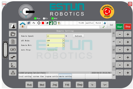
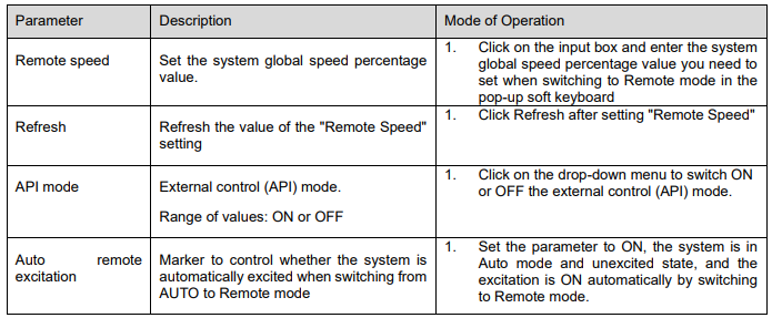
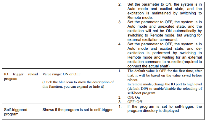
Step 5 Click on "Remote Settings" to go to the "Remote Settings" page.
Figure 4-60 Basic Settings - Remote Settings
4.7.3 Advanced Settings
1. This chapter introduces the "Local Settings" function in "Advanced Settings", other functions such as "Network Settings", "Lock Management", etc. are detailed in Chapter 7.
2. The functions in Advanced Settings are only available for the "Admin" user type. To use them, please first switch between users in "Home > User Login".
Local Settings
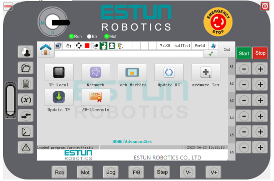
Step 1 Click "Advanced Settings" on the Home screen to enter the Advanced Settings interface, as shown in Figure 4-61.
Figure 4-61 Advanced settings interface
Step 2 Click on "Local Settings" in the Advanced Settings interface to enter the Local Settings interface, as shown in Figure 4-62.
Figure 4-62 Virtual Pendant - Local Setup Interface
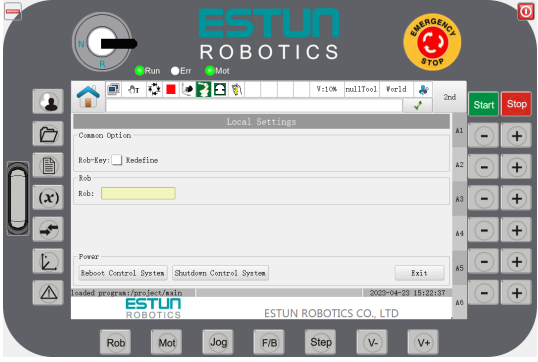
General settings:
Rob button: Check "Redefine", the Rob button does not allow access to the Quick Launcher.
Screen Brightness: User can set the screen brightness percentage and adjust the screen brightness (this takes effect immediately after setting; the set brightness is not changed by rebooting the teach pendant).
Robot (only displayed in the virtual pendant):
Settings for the marking robot. Only displayed when using the virtual programming pendant to set the ID of the marking robot.
Teach pendant timeout inactive (only displayed in physical teach pendant): screen off and logout if selected by default
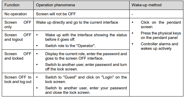
Timeout time (minutes): 5 minutes by default. Setting range 1 - 360 (minutes).
Save: Click the "Save" button when finished to write the parameters to a file and prompt for a reboot to take effect.
Note
⚫ The presence of pop-ups such as soft keyboards, prompt message boxes etc. will not trigger a timeout event.
⚫ This function is only supported on physical teaching pendant and the screen OFF function is only supported on T76 pendant.
⚫ Timeout inactivity includes: failure to tap on the pendant screen; failure to press any physical button on the pendant; failure to turn the key switch, etc.
Power Management:
Reboot Control System:
- When the controller is rebooted, the virtual pendant closes the virtual pendant program and the pendant reboots. After clicking on the "Reboot controller system" button, a password must be entered and the password is checked successfully before the controller can be rebooted.
Switch OFF the Control System:
- When the controller is switched off, the virtual pendant switches off the virtual pendant program and the physical pendant enters a selectable interface: pendant maintenance mode. After clicking on the "Switch OFF Control System" button, enter the password, and close the controller after a successful password check.
Turn OFF the Teach Pendant:
- After clicking on the "Close Teach Pendant" button, you will need to enter your password and switch off the pendant after a successful password check.
Virtual Teach Pendant: If you are currently using a virtual pendant, close the pendant program.
Physical Teach Pendant: If you are currently using a physical pendant, you can access the selection screen: Pendant Maintenance Mode
No comments to display
No comments to display