
2. Transportation & Installation
2.1 Handling Procedures

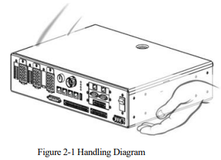
2.1.1 Installation requirements
Environmental requirements:
The operating environment temperature should be between 0°C and 45°C. During transportation and maintenance, the temperature range should be -20°C to 60°C.
The relative humidity should not exceed 95%RH, and there should be no condensation.
The installation site should have minimal dust, powder, oil fumes, and water.
Flammable substances, corrosive liquids, and gases are not allowed in the operating area.
The control cabinet should be installed in a low vibration or low impact energy environment (vibration below 0.5G).
There should be no nearby electrical interference sources (e.g. gas shielded welding TIG equipment).
There should be no potential hazards of collision with moving equipment (e.g. forklifts).
There should be no ion or non-ion interference.
Instructions for Users:
Please refer to the Instructions for Users and standardize your work.
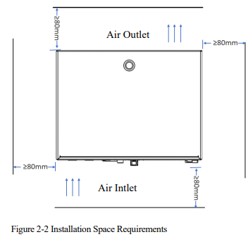
Requirements for installation space:
The installation space is shown in the figure below. Reserve the space for heat dissipation.
2.2 Installation Methods
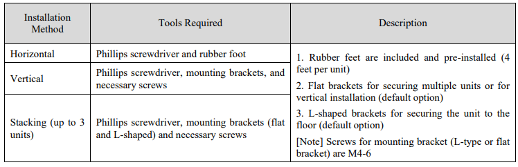
The control cabinet supports three installation methods: horizontal, vertical, and stacking up to three units.
The required tools for each method are listed below:
2.2.1 Horizontal installation
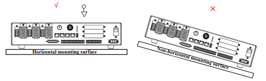
For standard installation scenarios, ensure the surface is flat and not deformed.
Installing steps:
Step 1 Check if the rubber feet at the bottom of the control cabinet are securely installed. In case of loosening or not installed, tighten the rubber feet using a Phillips screwdriver (rubber feet are pre-installed at the factory).
Step 2 Place the control cabinet on the installation surface as shown below to complete the horizontal installation.
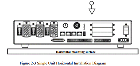
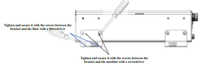
Step 3 (Optional) In severe environments (e.g. prone to vibration), use the included L-shaped brackets and screws to secure the cabinet. Install the brackets on both sides of the cabinet and fix them with screws to the mounting surface.
2.2.2 Vertical installation
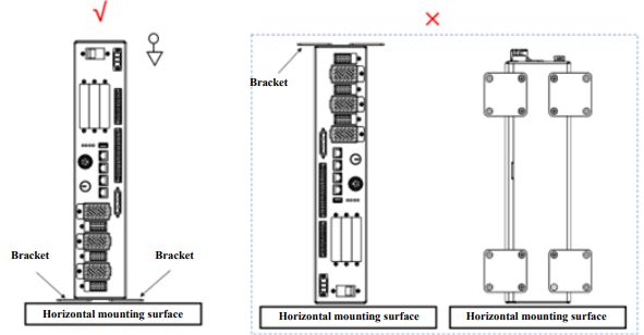
For vertical installation scenarios, ensure the surface is flat and not deformed.
Installing steps
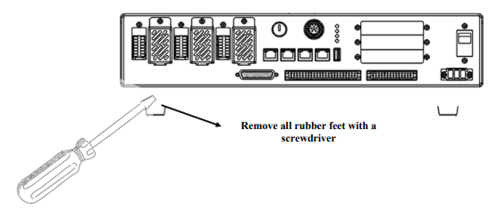
Step 1 Use a screwdriver to remove the screws from the four rubber feet and store the feet and screws properly.
Step 2 Install the flat brackets on the side without the nameplate, as shown below.
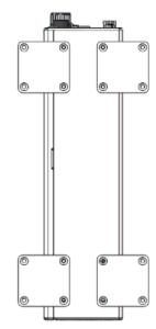
Step 3 Rotate the cabinet toward the side with the installed brackets and place it steadily on a flat surface.
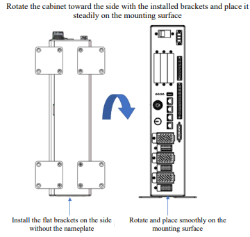
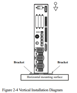
Step 4 Secure the brackets to the mounting surface using screws as shown in figure below, to complete the vertical installation.
Installation Dimensions
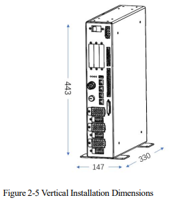
2.2.3 Stacking installation
For stacking multiple units, ensure the surface is flat and not deformed. Stacking allows for efficient use of space. It supports up to three control cabinets.
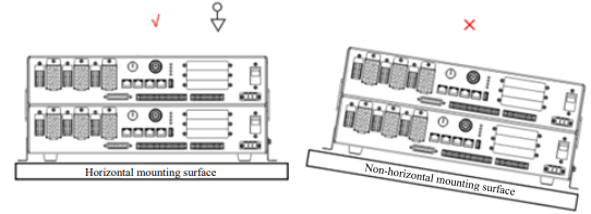
Installing Steps
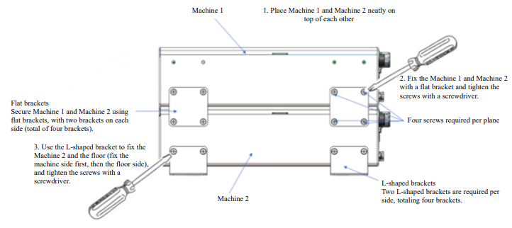
Take stacking of 2 machines as an example, and the installing steps are detailed below:
Step 1 Use a screwdriver to remove the screws from the four rubber feet of the first unit and store the feet and screws properly.
Step 2 Place the first unit neatly on top of the second unit. Use the included flat brackets and screws to secure the units on both sides, and then fasten with a screwdriver.
Step 3 Use L-shaped brackets to secure the units to the floor, and tighten them with a screwdriver.
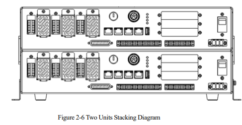
Step 4 This completes the stacking of two units, as shown below.
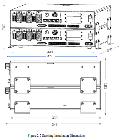
Installation dimensions

No comments to display
No comments to display