
4. (Optional) Expansion Cards
4.1 Expansion Slot Description
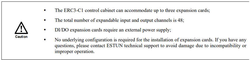
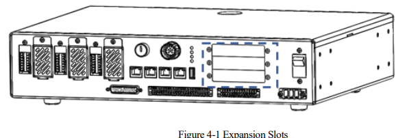
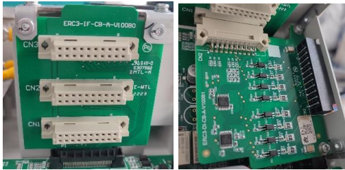
Expansion cards are optional accessories developed for customer applications. The ERC3-C1 control cabinet can accommodate up to three expansion cards.
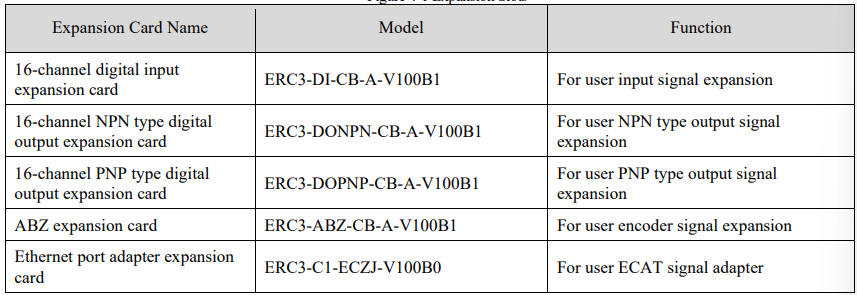
The types of expansion slots can be freely combined. Available expansion cards include:
16-channel digital input expansion card (up to 3 DI expansion boards can be installed, providing a maximum of 48 DI channels);
16-channel NPN type digital output expansion card (up to 3 DO expansion boards can be installed, providing a maximum of 48 DOs);
16-channel PNP type digital output expansion card (up to 3 DO expansion boards can be installed, providing a maximum of 48 DOs);
ABZ expansion card (up to 1 ABZ expansion card can be installed);
Ethernet port adapter expansion card (up to 1 Ethernet port adapter expansion card can be installed, only in the top slot CN3).
4.2 Installing Steps
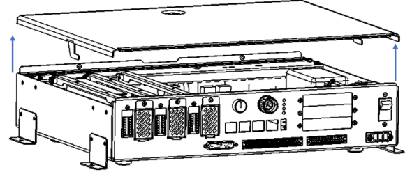
Step 1 Use a screwdriver to remove the two captive screws at the back of the control cabinet's top cover.
Step 2 Push the control cabinet cover backward horizontally with both hands.
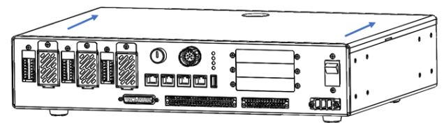
Step 3 Open the control cabinet cover as shown in the figure below.
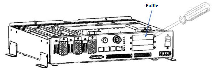
Step 4 Unscrew the expansion card front panel screws with a screwdriver.
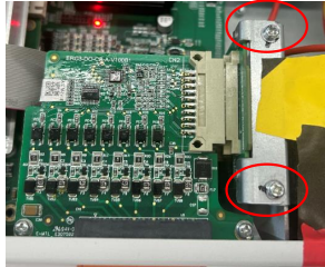
Step 5 Loosen the screws in the red circle a bit to better fit the expansion card.
Step 6 Insert the expansion card into the corresponding slot in the control cabinet, see “4.1 Expansion Slot Description” for correspondence.
Step 7 Secure the expansion card with screws.
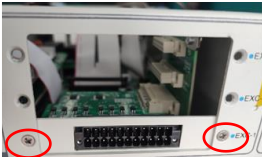
Step 8 Tighten the previously loosended screws.
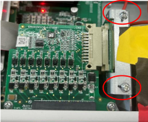
Step 9 Close the control cabinet cover and push it forward horizontally with both hands
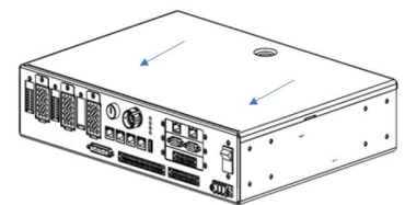
Step 10 Tighten the two screws at the back of the control cabinet's top cover with a screwdriver.
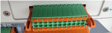
Step 11 Install the plug
4.3 DI Expansion Card
4.3.1 Expansion card information

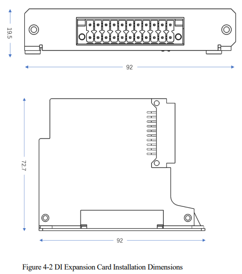
4.3.2 Installation dimensions
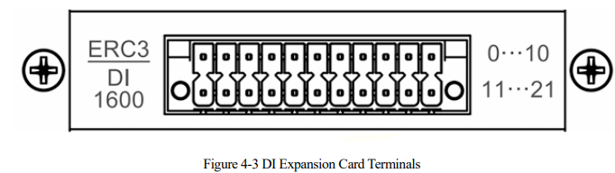
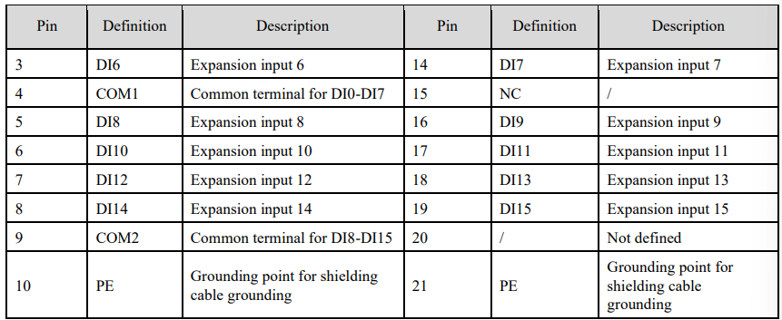
4.3.3 Terminal definitions

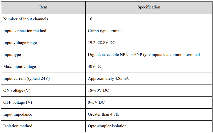
4.3.4 Port specifications
4.3.5 External wiring diagram
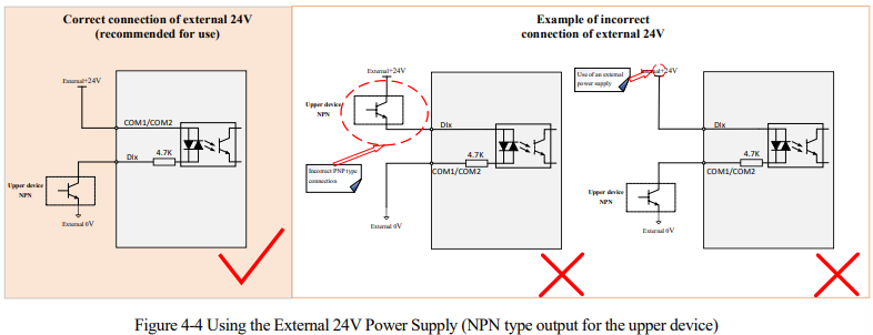
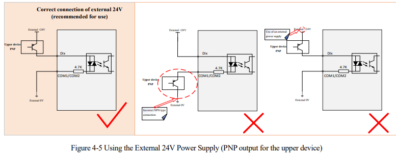
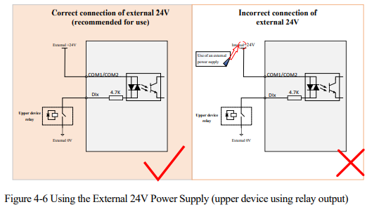
The DI signal input can use common anode and common cathode wiring methods, divided into signal pins DI0-DI7 with the corresponding common terminal COM1, and signal pins DI8-DI15 with the corresponding common terminal COM2.
When the upper device has open-collector output
(1) Common cathode wiring method (NPN output for upper device)
(2) Common anode wiring method (PNP output for upper device)
When the upper device has relay output

4.4 DO Expansion Card
4.4.1 DO expansion card description
The DO expansion card is divided into a 16-channel NPN type digital output expansion card and a 16-channel PNP type digital output expansion card. Users can select according to their needs.
4.4.2 DO expansion card information

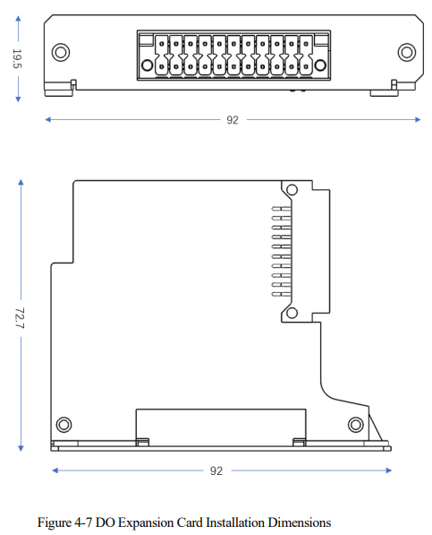
4.4.3 Installation dimensions
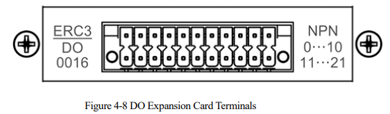
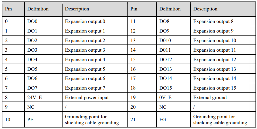
4.4.4 Definition of NPN type digital output expansion card terminal
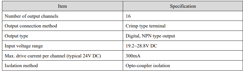
Port Specifications
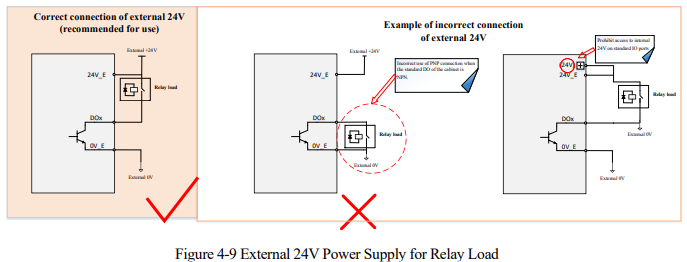
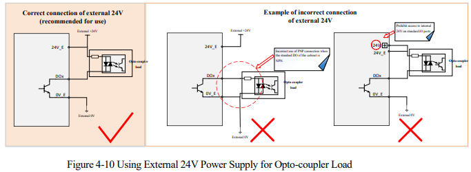
NPN Type DO External Wiring Diagram
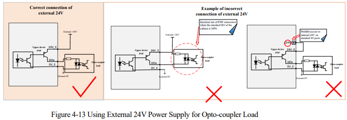
The following diagram illustrates external wiring for loads such as opto-couplers or relays.
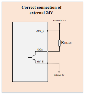
When the load is a relay
When the load is an opto-coupler

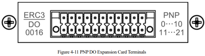
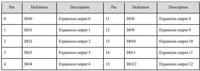
4.4.5 Definitions of PNP type digital Output expansion card terminals
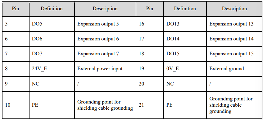
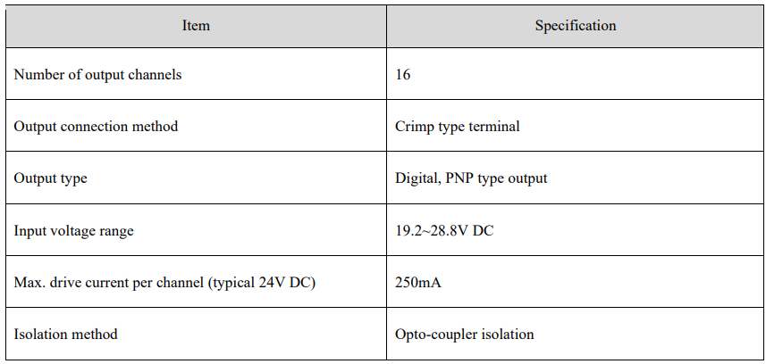
Port Specifications
DO External Wiring Diagram (PNP Type)
The following diagram illustrates external wiring for loads such as opto-couplers or relays.
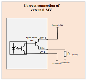
When the load is a relay
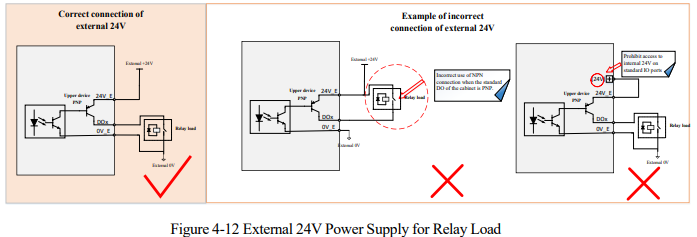
When the load is an opto-coupler

4.5 ABZ Expansion Card
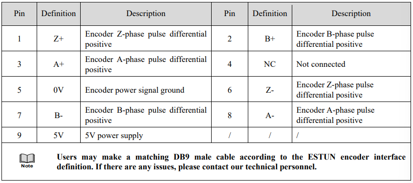
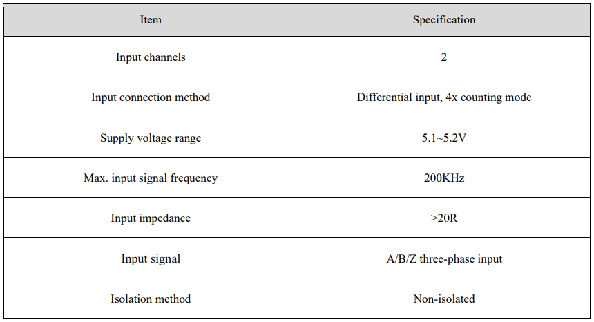
The interface of ABZ expansion card is for high-speed pulse input signals, allowing users to connect an external incremental encoder. The control cabinet can detect its feedback signals and convert them into data information for corresponding software applications.
The ABZ encoder expansion card (a maximum of 1 ABZ expansion card) can be installed. If you need to use the expansion card function, please contact our technical personnel first.
4.5.1 Expansion card information

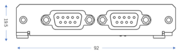
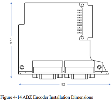
4.5.2 Installation dimensions
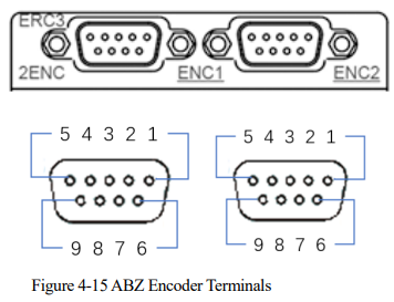
4.5.3 Terminal definitions
Port Specifications
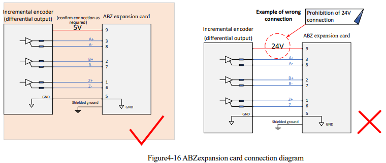
4.5.4 Wiring Method
The wiring of the ABZ expansion card is shown in the following figure.
4.6 Ethernet port adapter Expansion Card
The Ethernet port adapter expansion card (a maximum of 1 Ethernet port adapter expansion card can be connected) can be selected according to the user's needs.
4.6.1 Expansion card information

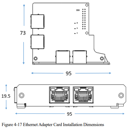
4.6.2 Installation dimensions
4.6.3 Terminal definitions
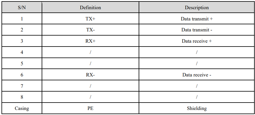
The ECAT1 interface definition is as follows:
4.6.4 Recommended communication cables
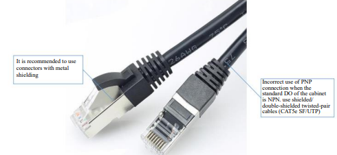
Please use a Cat 5e shielded/dual-shielded twisted-pair cable (CAT5e SF/UTP). It is recommended to use connectors with metal shielding layers to prevent signal interference.
4.6.5 Netword Port Adapter Expansion Card Network Cable Connection
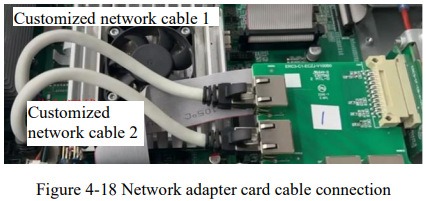
After installing the expansion card according to “4.2 Installing Steps”, users need to connect two network cables to the controller side of the network port, the network cable connection is shown in the following figure.
4.6.6 Wiring method
The wiring method for the Ethernet port adapter expansion card is shown in the following diagram.
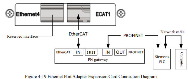
Note: See supporting documentation for controller software configuration “Configuration Manual for Communication Gateway EC2PN-GW-A of ER Series Industrial Robots RCS2”

No comments to display
No comments to display