
3. Wiring
3.1 Wiring Precautions
Installation, wiring, maintenance, and inspection of the product should only be carried out by personnel who have received training in electrical equipment, possess sufficient electrical knowledge, and are familiar with electrical safety protocols.
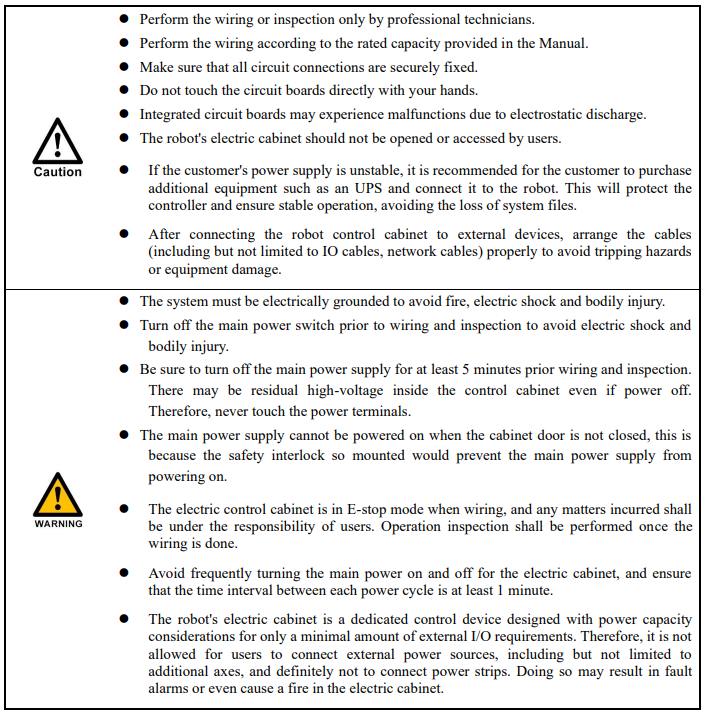
Before connecting the power line of the robot control cabinet to the grid terminal, it is recommended to connect it to a circuit breaker or disconnector first to prevent short circuits from affecting other equipment. The power supply wiring diagram for the robot control cabinet is shown below:
3.1.1 Selection of circuit breaker/air switch
The robot's motion trajectory involves a repetitive acceleration-deceleration process. As a result, the control cabinet experiences repetitive instances of high transient current in its input. This imposes specific requirements on the rated current and type of upstream circuit breakers or disconnectors. Additionally, being a frequency-controlled industrial device, the design and operational principles of the robot control cabinet inherently lead to a certain level of leakage current.
1. Selection of circuit breaker/air switch with leakage protector
a) It is recommended to configure each robot control cabinet with a separate 10A, D-type circuit breaker or air switch. The leakage protector should have a sensitivity current of ≥30mA and be of type B residual current device (RCD).
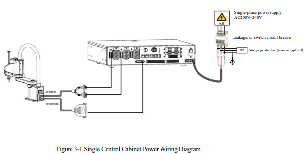
b) If two robot control cabinets share one circuit breaker or air switch, use a 20A, D-type circuit breaker or air switch with a leakage protector of ≥30mA sensitivity current. No other electrical equipment should be connected under this leakage protector to prevent additional leakage currents that could cause a total leakage current above 30mA and result in a trip.
c) If connecting multiple devices under one circuit breaker or air switch with a leakage protector, the current value and leakage current protection value of the air switch or circuit breaker should be multiplied based on the configuration value of a single unit.
2. Selection of circuit breaker/air switch without leakage protector
a) It is recommended to configure each robot control cabinet with a separate 10A, D-type air switch or circuit breaker.
b) If two robot control cabinets share one air switch or circuit breaker, use a 20A, D-type air switch or circuit breaker.
c) When connecting multiple devices under one circuit breaker or air switch, multiply the current value of the circuit breaker or air switch based on the configuration value of a single unit.
3.1.2 Power Cable Selection
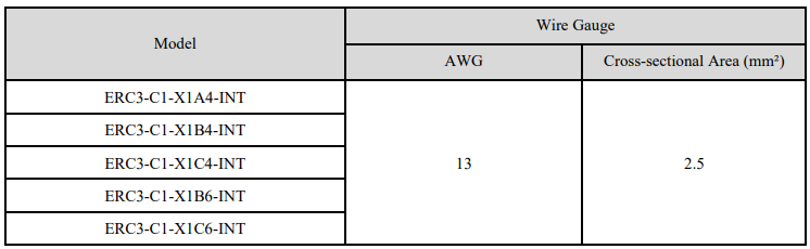
ESTUN control cabinets are not equipped with input power cables. Users need to provide their wiring or purchase from ESTUN. When choosing cables, comply with the relevant safety standards. The recommended cable specifications are as follows.
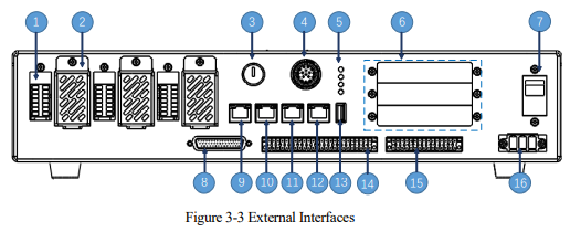
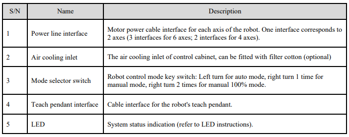
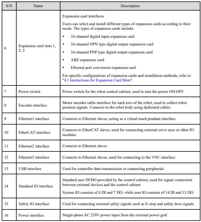
3.2 External Interface Description
3.3 Connection Diagram
3.4 Power supply wiring
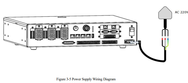
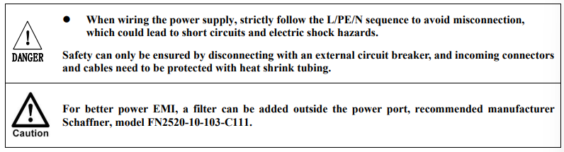
The control cabinet uses single-phase AC 220V power. Follow the diagram below for power line preparation and correct wiring.
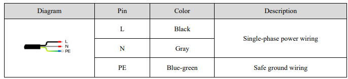
Wiring steps:
Check the markings and precautions on the control cabinet power input terminal and wiring terminal before wiring. Strictly adhere to relevant operating standards.
Step 1 Take out the input terminals from the accessory kit.
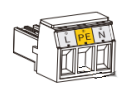
Step 2 Insert the three wires of the power line into the input terminal according to the terminal markings (from left to right: L/PE/N), and tighten securely.
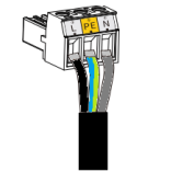
Step 3 After completing the power line connection, insert the input terminals into the power input terminal on the control cabinet.
3.5 LED Explanation
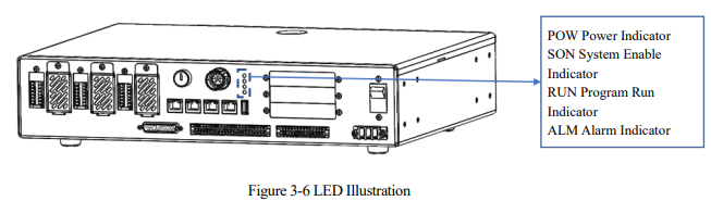
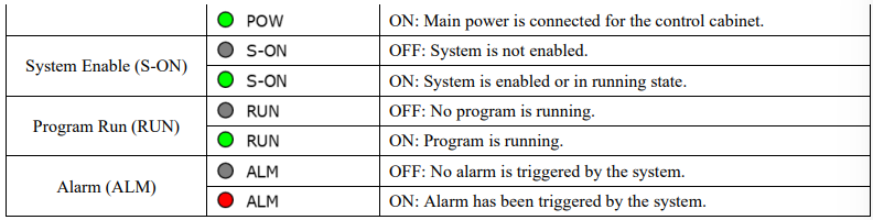
There are four LEDs on the control cabinet representing different operational states, with the following explanations:

3.6 Power Wiring
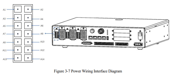
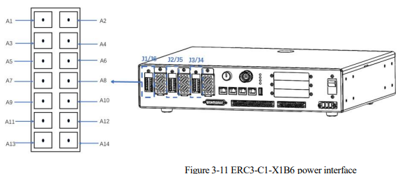
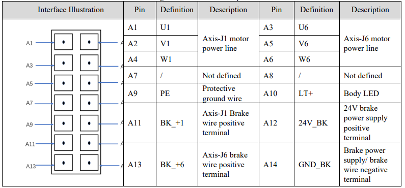
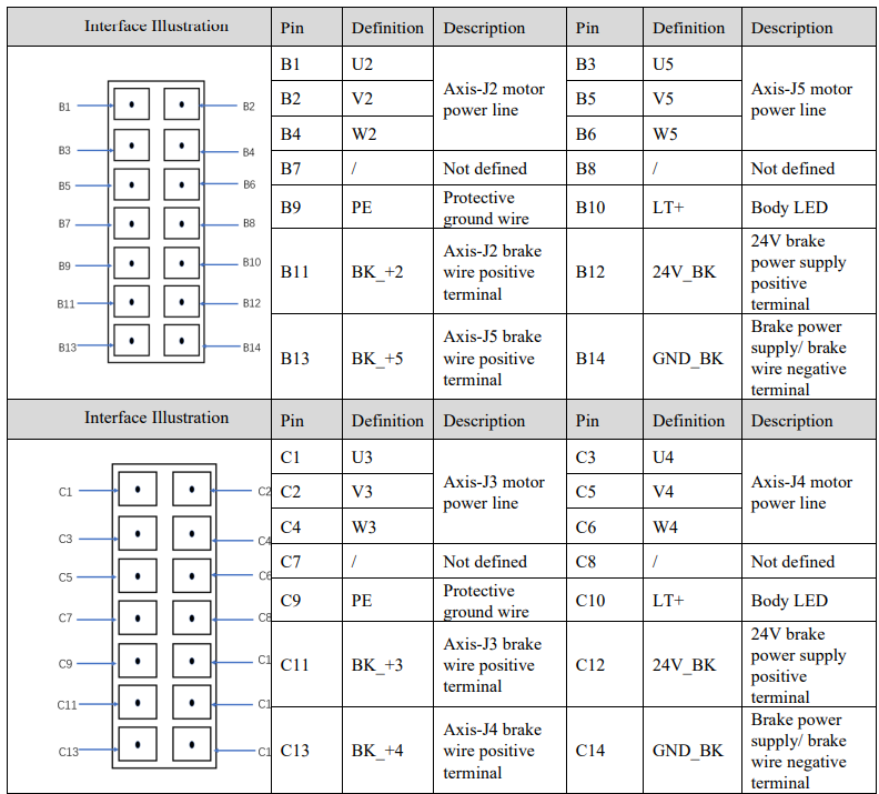
3.6.1 Power line interface explanation
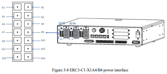
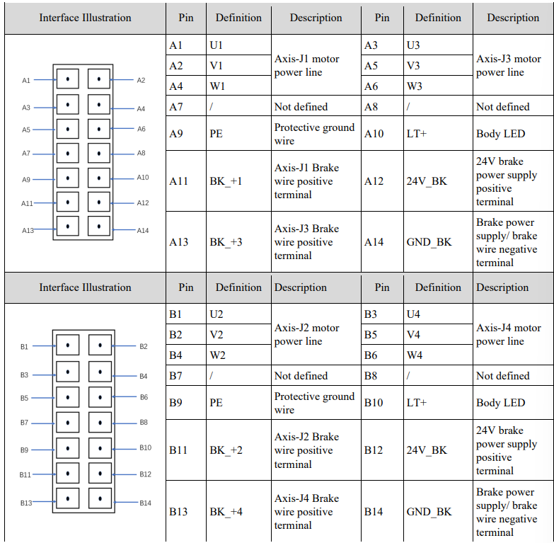
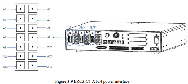
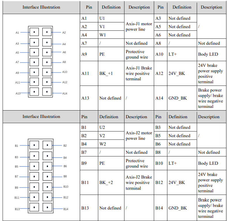
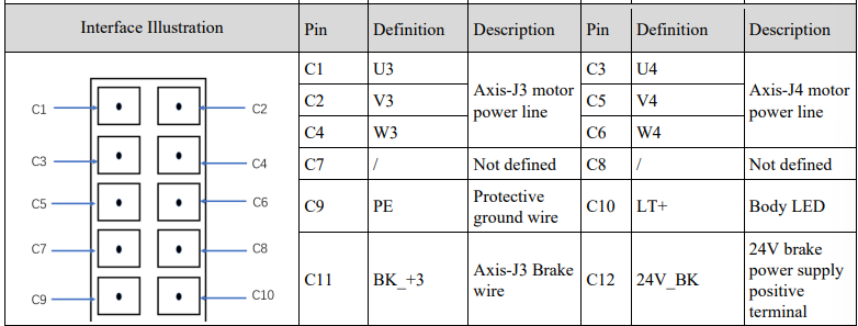
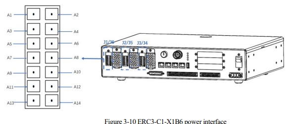
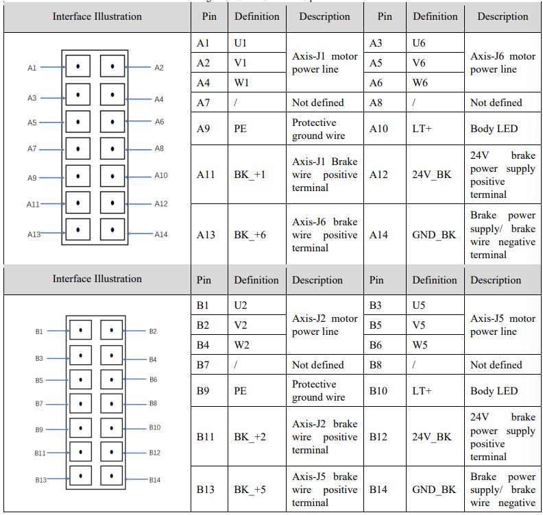
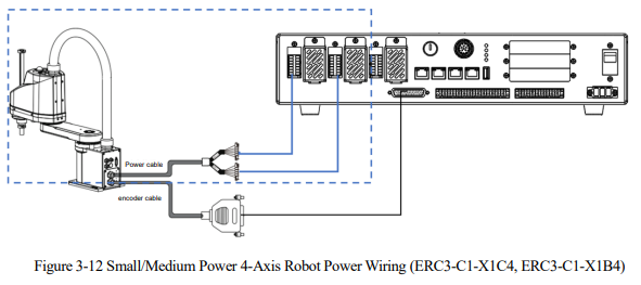
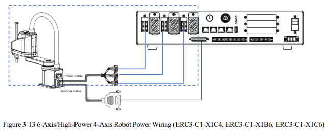
The encoder and power cables connecting the mechanical body and the controller have connection markings. Please connect the cables according to the markings of Axis1&6, Axis2&5, Axis3&4 (or Axis1&3, Axis2&4), and do not connect them incorrectly, as this may cause damage, which may prevent the robot system from working properly, and may also cause serious safety problems.
ERC3-C1-X1A4/B4 Small/Medium Power 4-Axis Power Interface
ERC3-C1-X1C4 High-Power 4-Axis Power Interface

ERC3-C1-X1B6 Medium Power 6-Axis Power Interface
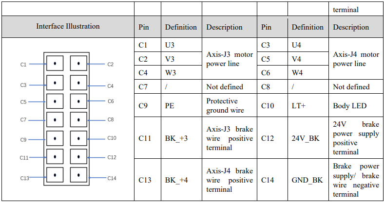
ERC3-C1-X1C6 High-Power 6-Axis Power Interface
3.6.2 Power line wiring
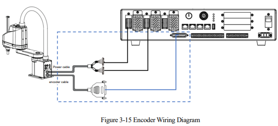
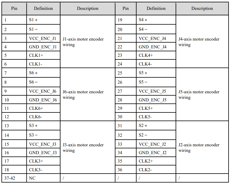
3.7 Encoder wiring
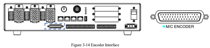
3.7.1 Connection diagram
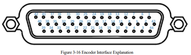
3.7.2 Encoder interface explanation
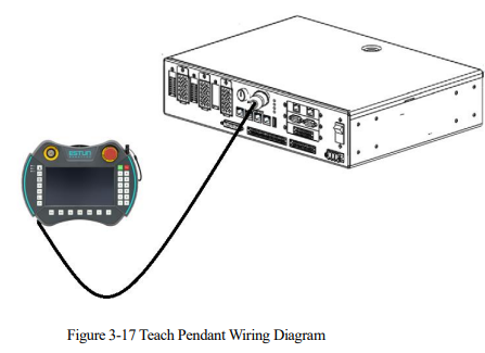
3.8 Teach pendant wiring
3.8.1 Precautions for using teach pendant
1. Handle with care and avoid dropping, throwing, or striking the teach pendant, as this may cause damage or malfunction. When not in use, hang it on the dedicated holder to prevent accidental dropping;
2. Do not use sharp objects such as screws, knives, or pen tips to operate the touch screen. This may damage the touch screen. Use your fingers or a stylus pen to operate the touch screen;
3. When no USB devices are connected, make sure to cover the USB ports with protective caps to avoid exposing them to dust, which could cause interruptions or failures;
4. When using USB plugs, do not apply excessive force. Normal use is sufficient;
5. If the USB is not recognized, unplug the USB drive, power off, and then plug it back in after powering on;
6. When using the E-stop button or key, do not apply excessive force. Normal use is sufficient;
7. The power-on time is 40 S for the system to start up properly. Do not power off prematurely to avoid file loss;
8. Connect or disconnect the teach pendant when the control cabinet is powered off. It is prohibited to connect or disconnect the teach pendant while the control cabinet is powered on, as this may result in damage to the controller or the teach pendant.
9. When storing cables, do not place them under heavy machinery to avoid crushing, cutting, or pulling them apart;
10. Follow our defined wiring guidelines to avoid connection errors and potential issues;
11. The teach pendant is not explosion-proof. Do not use it in explosive environments or work units;
12. Keep the teach pendant away from water, oil, and similar environments;
13. The ERC3-C1 control cabinet is only compatible with the T76 model of teach pendant and cannot be paired with the T72 model.
14. To release the E-stop, lift the E-stop button upward or rotate the button to release it. Avoid excessive rotation or pausing during rotation, as this may cause abnormal dual-channel detection of the system, and trigger alarm codes A112/A113. In the event of abnormal alarms A112/A113 during non-routine operations, manually clear the alarm for normal operation.
15. To correctly use the teach pendant push button, support the bottom of the teach pendant with the palm of the left hand and simultaneously press the middle position of the teach pendant with two fingers of the left hand. For ease of operation, the push button is designed as a rectangle. Using only one finger to apply force at the upper or lower end of the rectangle may result in failure to close one set of contacts, triggering alarm codes A11A/A11B. In the event of alarms A11A/A11B during non-routine operations, manually clear the alarm for normal operation.
16. When switching between Manual and Auto modes using the mode switch on the control cabinet, do not pause in the middle position during the switch. The middle position of the mode switch is the critical point for mechanical contact closure. Pausing at this position may cause alarm codes A116/A117. In the event of abnormal alarms A116/A117 during non-routine operations, manually clear the alarm for normal operation.
17. If frequent switching between manual and automatic modes is required during testing, wait for 5 seconds after switching from manual to automatic mode for the system self-check to complete before switching back to manual mode. Rapid and frequent switching between manual and automatic modes may cause alarm code A1F due to incomplete self-checks. This is a normal phenomenon, and power cycling will resolve the issue.
18. In manual mode, if frequent pressing of the teach pendant button is required, wait for 5 seconds after pressing the button before releasing it, to allow time for the system self-check to complete. Rapid and frequent switching between Manual and Auto modes may cause alarm code A1F due to incomplete self-checks. This is a normal phenomenon, and power cycling will resolve the issue
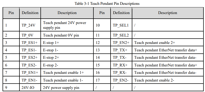
3.8.2 Teach pendant interface description
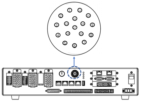
Figure 3-18 Teach Pendant Interface Description
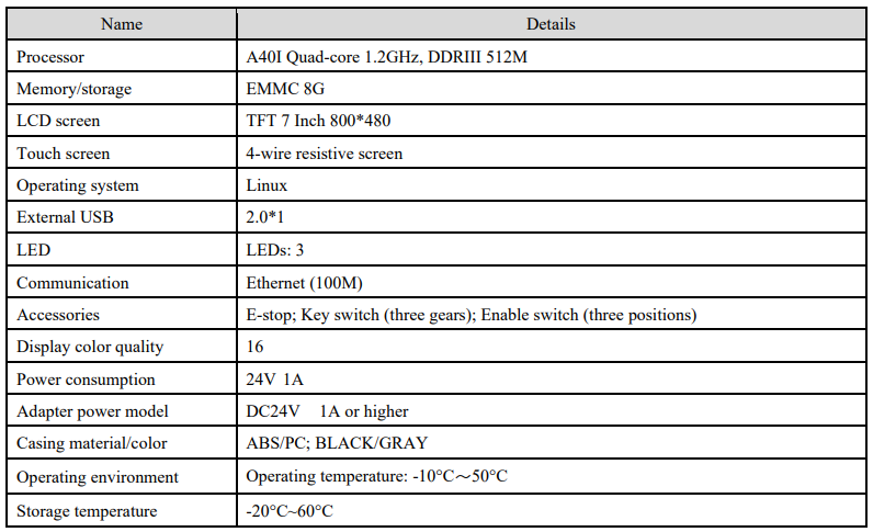
3.8.3 Teach pendant specifications
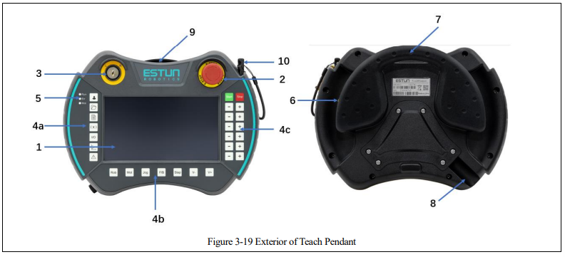
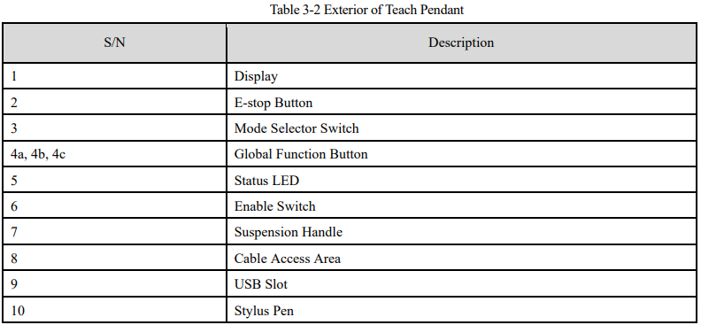
3.8.4 Appearance of teach pendant
3.9 IO Wiring
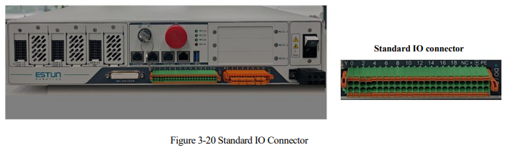
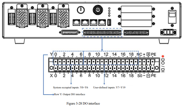
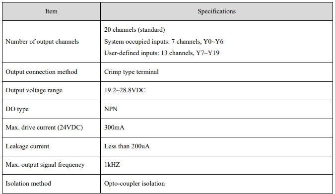
This section provides an overview of the DI/DO interfaces of the standard control cabinet, which includes 20 DIs and 20 DOs by default. The system occupies 6 DIs (X0~X5) and 7 DOs (Y0~Y6), while the user can define the usage of the remaining 14 DIs (X6~X19) and 13 DOs (Y7~Y19).
If there are insufficient inputs and outputs, the IO can be expanded using an expansion card, as described in the (Optional) Expansion Cards section.
3.9.1 DI wiring
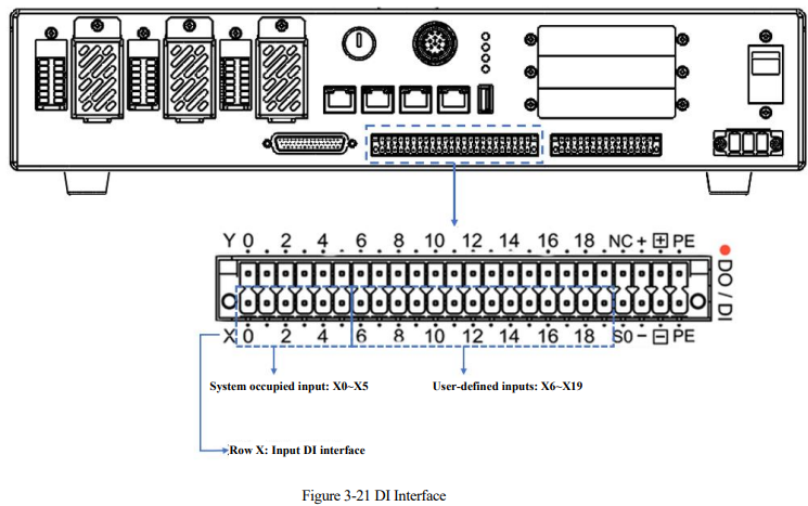
DI Port Specifications
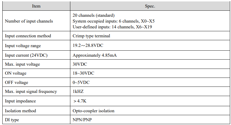
DI Interface Definitions

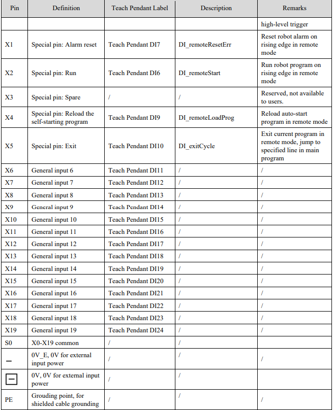 Note: DI1-DI10 on the oscillator ports are occupied by the system, and ports with dedicated pins noted in the table above are not available to the user.
DI Signal Wiring
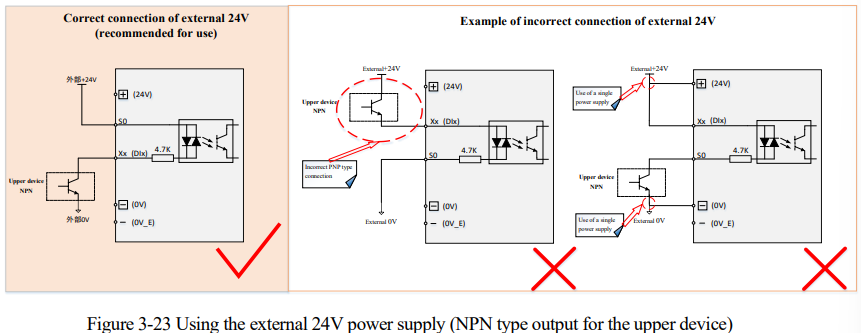
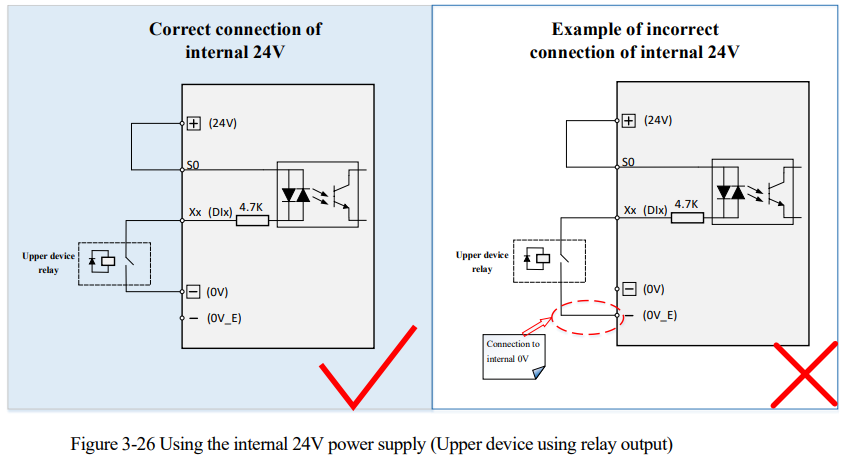
Input DI signals can be connected using both common anode and common cathode methods, divided into signal pins X6-X19 and common terminal pin S0. The wiring method for extending DI output signals is the same as above.
Wiring Diagram
When the upper device is open collector output:
(1) Common cathode method (upper device with NPN type output)
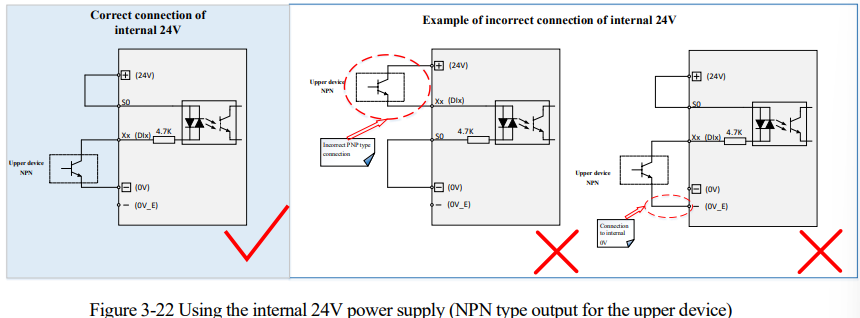
(2)Common anode method (PNP type output)
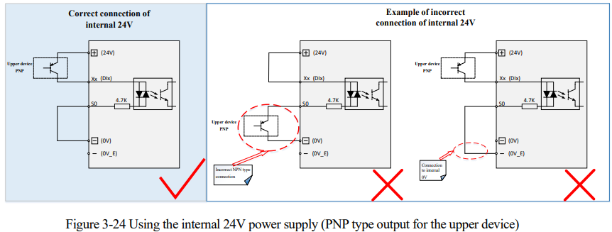
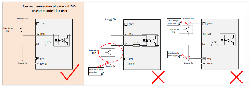
Figure 3-25 Using the external 24V power supply (PNP type output for the upper device)
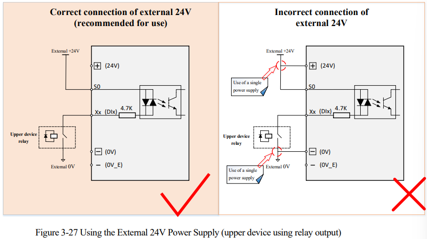
When the upper device is of relay output
3.9.2 DO wiring
DO Port Definitions
DO Port Definitions

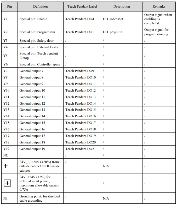
Note: DO1-DO10 on the oscillator ports are occupied by the system, and ports with dedicated pins noted in the table above are not available to the user.
DO Signal Wiring
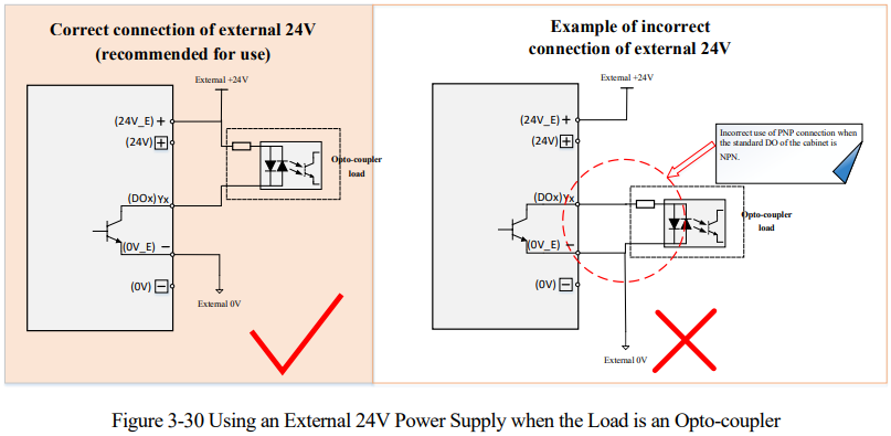
The following diagrams illustrate wiring for loads using opto-couplers/relays. The wiring for extending DO output signals is the same.
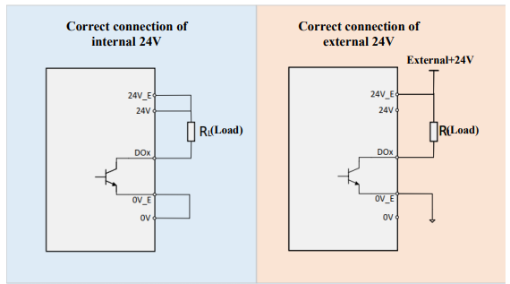
When the load is a relay
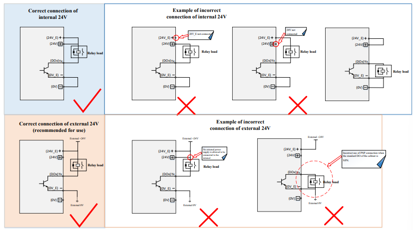
Figure 3-29 External/Internal 24V Power Supply when Load is a Relay
When the load is an opto-coupler
3.10 Communication Connection
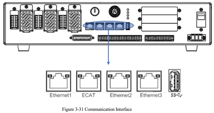
3.10.1 Communication signal description
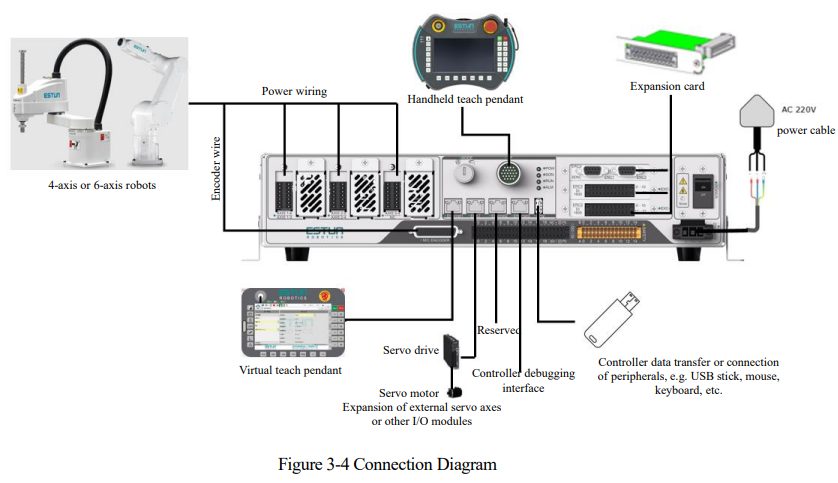
EtherNet1 is used to connect to the virtual teach pendant;
EtherNet2 is a reserved communication interface;
EtherNet3 is used for controller debugging.
EtherCat is used to connect external servo axes or other I/O modules.
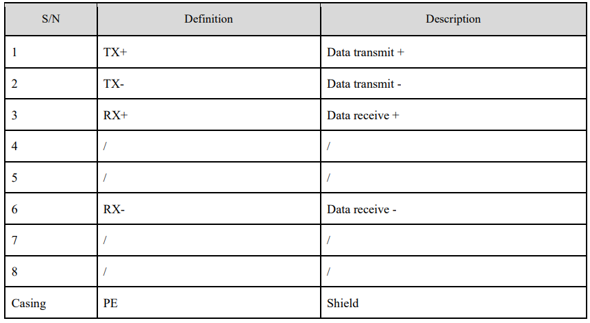
The definitions for EtherCAT and EtherNet interfaces are as follows:
3.10.2 Recommended communication cables
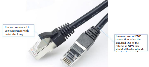
Please use shielded/double-shielded twisted-pair CAT5e SF/UTP cables for communication. It is recommended to use connectors with metal shielding to prevent signal interference.
3.10.3 USB interface
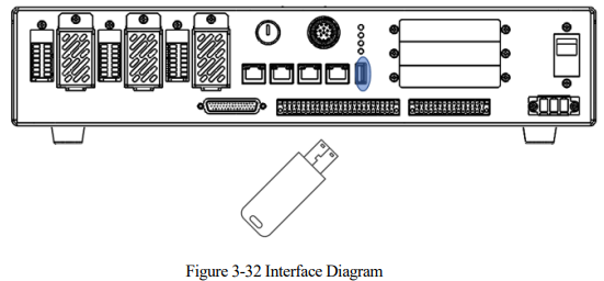
The USB interface on the controller is used for data transfer or connecting peripherals such as USB drives, mice, keyboards, etc.
3.10.4 EtherCAT wiring
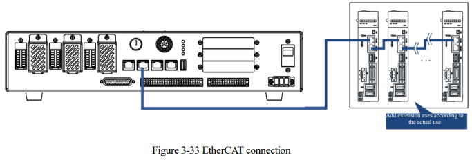
The control cabinet can act as the master station for EtherCAT communication to connect EtherCAT communication devices such as Trio modules, ED3S servo drives (as extension axes).
3.11 SAFETY IO
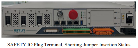
The ERC3-C1 control cabinet comes standard with a variety of safety stop methods. The SAFETY IO interfaces are illustrated in the following diagram.
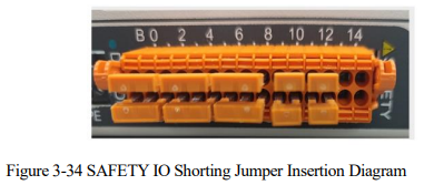
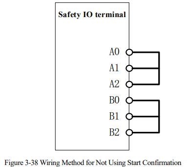
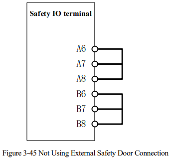
By default, shorting jumpers are inserted into the SAFETY IO, rendering the corresponding functions inactive. To use these functions, the respective shorting jumpers must be removed, and connections must be estaed following the appropriate wiring methods.
It is strongly advised not to remove the shorting jumpers if these functions are not in use, as doing so may trigger the corresponding functionalities, leading to operational halts or alarms.
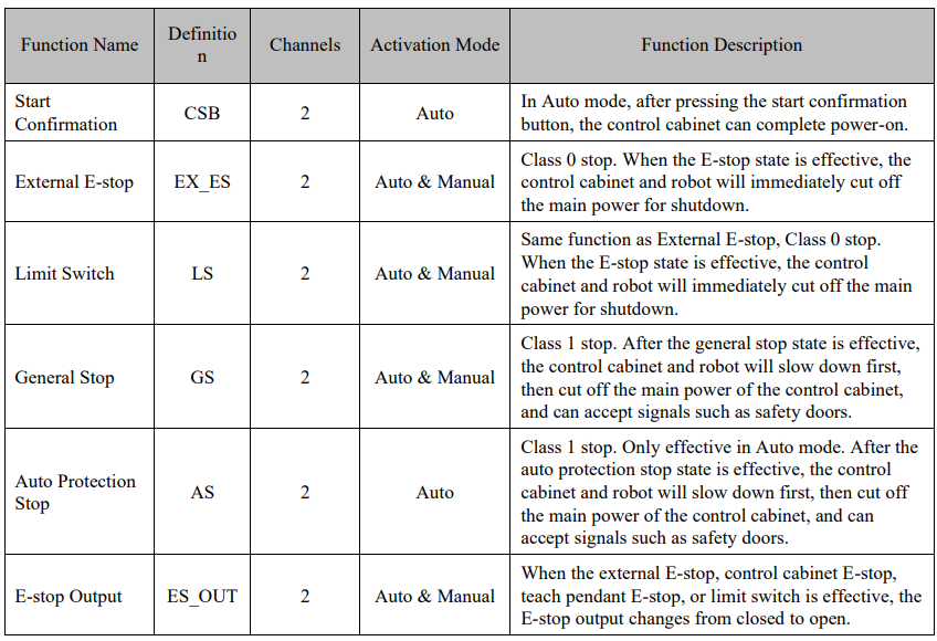
The input and output signals related to safety stop and their functions are described below:
3.11.1 SAFETY Interface Description
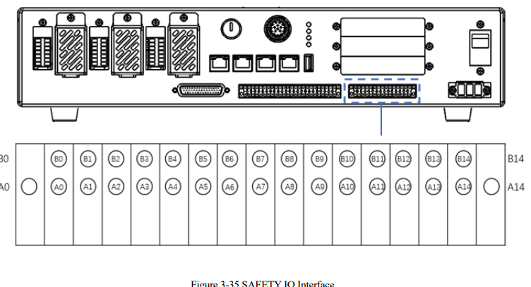
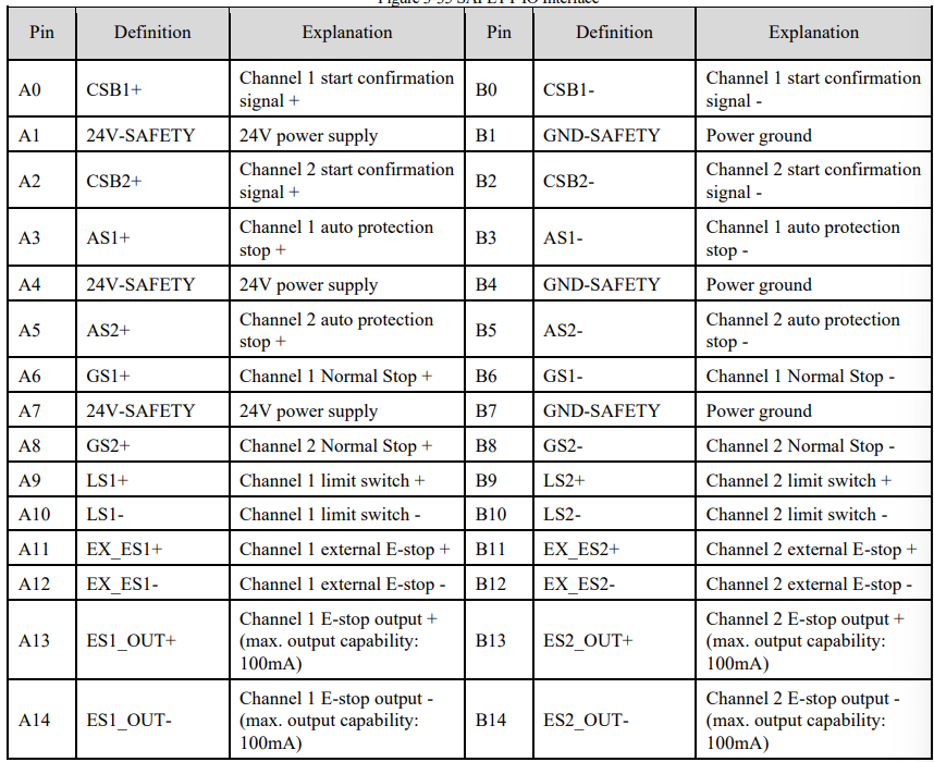
[Note] 24V-SAFETY provides a 24V power supply with a maximum output current of 80mA. It is prohibited to be used for external load drive!
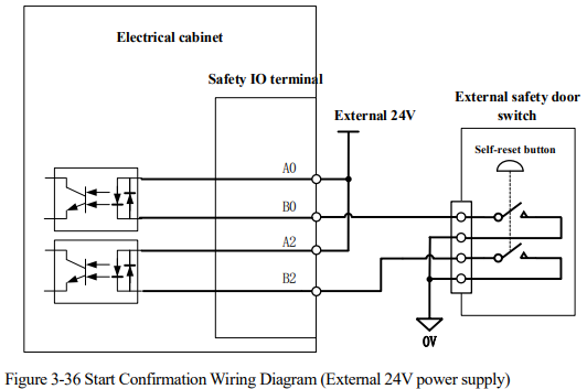
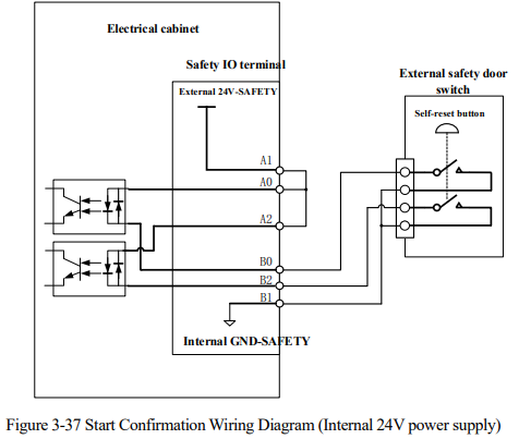
3.11.2 Start confirmation wiring method
When using the start confirmation function, connect the CSB- and CSB+ to a self-resetting NO switch externally. The main power of the control cabinet will only be turned on after pressing the start confirmation button. Its wiring method is as follows:

When the start confirmation function is not used, short-circuit using a jumper, with the specific wiring method as follows:
3.11.3 External E-stop wiring method

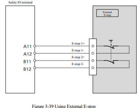

When the external E-stop function is not used, short-circuit using a jumper, with the specific wiring method as follows:
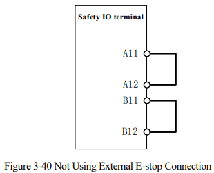
3.11.4 Limit switch wiring method
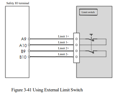

When not using the limit switch function, short-circuit using a jumper, with the specific wiring method as follows:
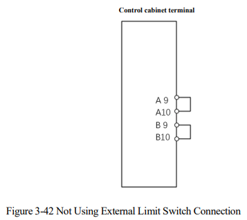
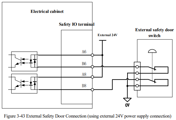
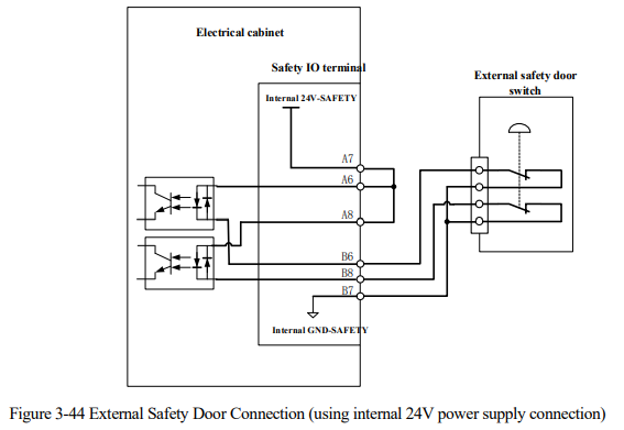
3.11.5 Safety door wiring method
Safety doors and safety light curtains can be used to control protective barriers and doors during robot operation.

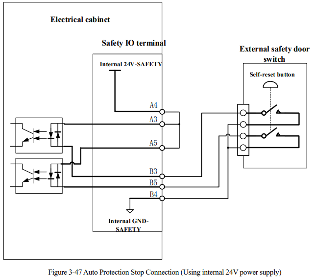
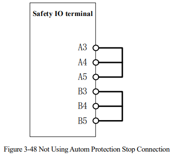
3.11.6 Auto protection stop wiring method
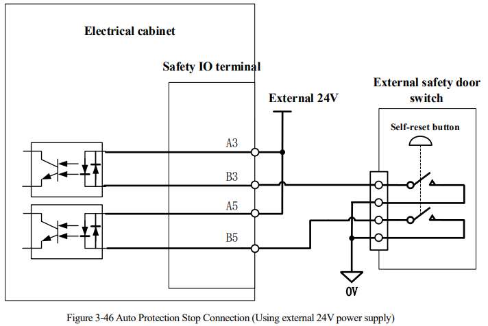
The wiring method for safety doors and safety light curtains in Auto mode is shown in the following figures:

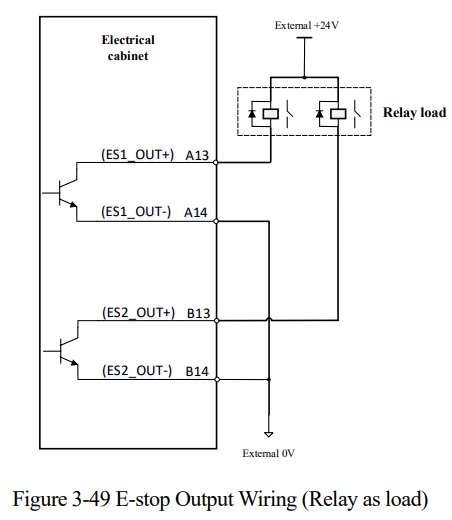
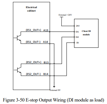
3.11.7 E-stop output wiring method
(1) Wiring method with relay as the load
(2) Wiring method with client DI module as the load
No comments to display
No comments to display