
1. Brief introduction
1.1 CAN main files
1.2 Terms and abbreviations
1.3 Brief introduction
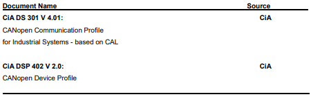
CANopen is a higher-layer protocol based on the CAN (Control Area Network) serial bus system and the CAL (CAN Application Layer). CANopen assumes that the hardware of the connected device has a CAN transceiver and a CAN controller as specified in ISO 11898.
The CANopen Communication Profile, CiA DS-301, includes both cyclic and event-driven communication, which makes it possible to reduce the bus load to minimum while still maintaining extremely short reaction times. High communication performance can be achieved at relatively low baud rates, thus reducing EMC problems and cable costs.
CANopen device profiles define both direct access to drive parameter and time-critical process data communication. The NCAN-02 fulfils CiA (CAN in Automation) standard DSP-402 (Drives and Motion Control), supporting the ‘Manufacturer Specific’ operating mode only.
The physical medium of CANopen is a differentially-driven two-wire bus line with common return according to ISO 11898.
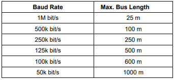
The maximum length of the bus is limited by the communication speed as follows:
The maximum theoretical number of nodes is 127. However, in practice, the maximum number depends on the capabilities of the CAN transceivers used.Each node is an independent CANopen device, which contains maximum 8 logical devices.And one logical device controls one axis for servo drive.
The model of CANopen device is as below:
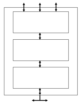
1、Communication interface
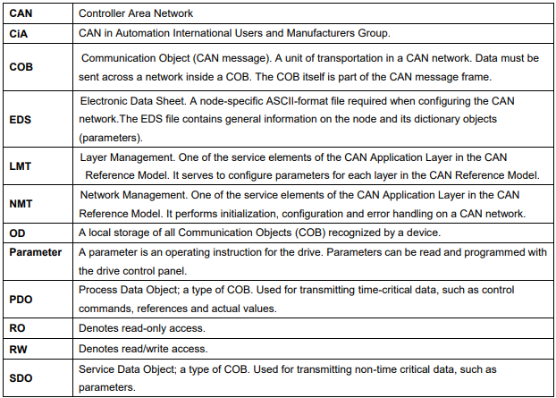
Communication interface defines PDO, SDO, NMT and other protocol about message transmission.
2、Object Dictionary
The key concept of CANopen is device Object Dictionary,which is used in other live bus (Profibus,Interbus-S). CANopen can visit all the parameters of the servo drive by OD.Notes: OD is not a part of CAL, but relised in CANopen. The object of OD can be recognised by a 16 bit index and a 8 bit index (please refer to Appendix Object dictionary). OD is classified by CANopen as below:
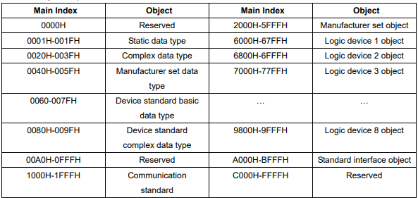
The most commonly used object:
1)1000H-1FFFH,communication standard object,to realize network configuration and PDO mapping,etc.
2)2000H-5FFFH, manufacturer specified object, to realize read and write Pn xxx parameters.
3)6000H-9FFFH, Logic device 1-8 object, which belong to CIA 402 device sub-protocol. It is possible to operate these objects for carry out a variety of servo drive modes. Each logic device is related to one axis, so, ProNet can index the objects in the range of 6000H-67FFH, and the EDS drive can index the objects in the range of 6000H-6FFFH, and that the ETS can index the objects in range of 6000H-9FFFH. To get the corresponding objects of the second-axis and the third-axis, separately shifted the objects of first axis to 0800H and 1000H. For example, the control word of the first-axis which of the index is 6040H, well than, the control words for the second-axis and the third-axis are 6840H and 7040H respectively. Also, it is possible to find the index of the corresponding objects by the object dictionary in the appendix. For the operational mode, this manual only takes the using of the first-axis as the example. The operation of the second-axis and the third-axis are the same with it for the EDS and the ETS, so it is unnecessary to go into details.
3、Application
It controls parameters of servo drive and serval other assistant functions by serval operation mode. ProNet/EDS/ETS currently supports 4 control modes: profile position mode、profile velocity mode、profile torque mode、interpolation position mode and homing mode.
Further information can be obtained from the CAN in Automation International Users and Manufacturers Group (www.can-cia.de).
No comments to display
No comments to display