
2. Cabling and wiring
●The layout of CN3 terminal
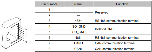
Note:
1. Do not short terminal 1 and 2 of CN3.
2. If connecting more than 16 CAN nodes,please contact ESTUN customer service.
● The layout of CN4 terminal
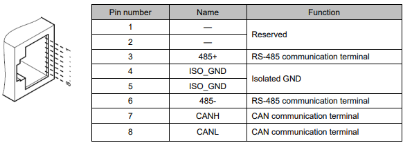
CN3 is always the input terminal of communication cable and CN4 is always the output terminal of communication cable. (If connection to another communication node is necessary, the cable will connect CN4 to next communication node. If not, a terminal resistor could be applied at CN4). When multiple ProNet devices are connected, it is forbidden to connect the CN3 terminals of different drives directly.
For example, a network is composed of one PLC, three ProNet drives called A, B and C. The cabling network is as below:
PLC → CN3 of drive A,CN4 of drive A → CN3 of drive B,CN4 of drive B → CN3 of drive C, CN4 of drive C → 120Ω resistor.
The two ends of the CAN cable have to be terminated by a resistor of 120Ω (1%, 1/4W) as below

Please select the bus cable with double twisted pair cables and shielding layer, one pair for connecting CAN-L and CAN-H, another pair for grounding.
No comments to display
No comments to display