
3. CANopen communication
CAL supplies all network management service and message transferring protocol with defining the content of object or type of object for communication. It defines how instead of what, which is the strength of CANopen.
CANopen is developed based on CAL. It applies CAL protocol subsets for communication and service and creates a solution to DCS. CANopen could freely extend the node function to simplicity or complex while the network nodes are accessible and available to each other.
The key concept of CANopen is object dictionary. This way of object description is also applied to other fieldbus system like Profibus and Interbus-S. CANopen communication could access to all the parameter of drivers through object dictionary. Please notice object dictionary is not one part of CAL, instead of which it is realized in CANopen.
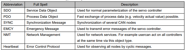
CANopen communication defines several types of objects as below…
CAN employs data frames for transferring data between the host (controller) and the nodes on the bus. The following figure presents the structure of the data frame

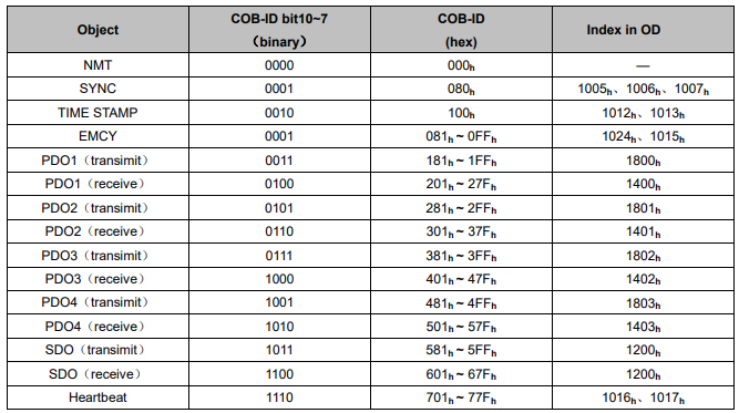
Our drivers doesn’t support remote frame currently. The detail of COB-ID is as below.

3.1 CAN identifier list
Note:
1. PDO/SDO‘s send/receive is observed by (slave) CAN.
2. Our drive‘s CANopen protocol currently supports 4 transimit PDO and 4 receive PDO.
3.2 SDO
SDO is used to visit the object dictionary of a device. Visitor is called client. The CANopen device whose object dictionary is visited and required to supply the asked service is called server. CANopen messages from a client and servo all contain 8 bits (Not all of them are meaningful). A request from a client must be confirmed by a server
There are 2 method of conveying SDO:
- Expedited transfer:contains 4 bytes at maximum
- Segmented transfer:contains more than 4 bytes
Basic structure of SDO:

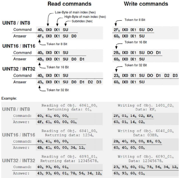
SDO read/write command structure:
SDO-error messages:

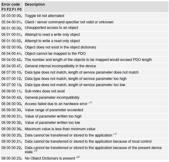
3.3 PDO
PDO is applied to transferring real time data which will be conveyed from a producer to one or multiple clients. Data transferring will be limited to 1 to 8 bytes. There is no hand-shake restriction in PDO communication, which means data has been redefined, so clients could process the received data for vary short time. PDO content will be only defined by its CAN ID, assuming producers and clients know PDO content from its CAN ID. 2 objects in object dictionary are used for each PDO.
■ PDO communication parameter:It contains COB-ID, transferring type, restriction time and cycle of timer used by PDO.
■ PDO mapping parameter:It contains a list of objects in the object dictionary. These objects are mapped into PDO,
includes their data length in bits. Producers and clients must know this mapping to explain the content of PDO. The content of PDO’s message is predefined or configured when the network initializes. Mapping application object into PDO is described in object dictionary. If a device (producer and client) support dynamic mapping, SDO could be used to configure PDO’s mapping parameter. Our servo drive supports dynamic PDO mapping. There are 2 rules for PDO mapping to follow..
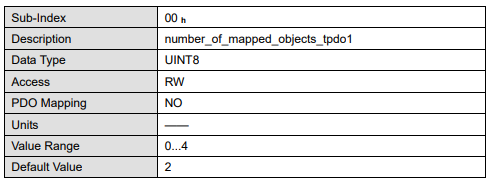
1. Each PDO could be mapped into 4 objects.
2. The length of each PDO will be no more than 64 bits.
PDO mapping process:
1. Set the sub-index of PDO coordinated mapping parameter (1600 h, 1601 h, 1A00 h or 1A01 h) as o.
2. Revise the sub-index from 1 to 4 of PDO coordinated mapping parameter (1600 h, 1601 h, 1A00 h or 1A01 h).
3. Set the sub-index 0 of PDO coordinated mapping parameter(1600 h ,1601 h,1A00 h or 1A01 h ) as legal number( number of PDO’s mapping objects)
4. PDO mapping completing.
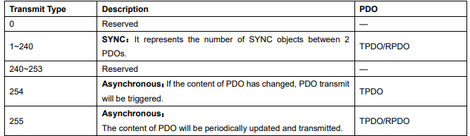
There are multiple ways to transmit PDO:
■ Synchronous(Synchronization by receiving SYNC object)
Cycle: Transmit triggered after every 1 to 240 SYNC messages.
■ Asynchronous
Transmit triggered by special object event regulated in sub-object protocol.
Transmit type of PDO
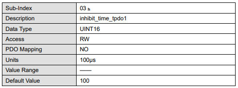
One PDO could set a frozen time which is the shortest interval time between 2 continuous PDO. It could prevent the bus from being occupied by amount of data with high priority. Frozen time is defined by 16 bit unsigned integer number and its unit is 100us.
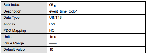
One PDO could set a timing period. When the regulated time is violated, a PDO transmit could be triggered without a trigger bit. Object timing period is defined as 16 bit unsigned integer and its unit is 1ms.
PDO mapping case:
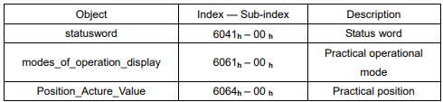
Map the 3 objects to PDO1 (transmit). PDO1 (transmit) is required to be asynchronous periodic type with period time as much as 10ms and frozen time as much as 2ms.
1)Clear number_of_mapped_objects
number_of_mapped_objects(1A00 h:00 h)= 0
2)Set the parameter for mapping objects
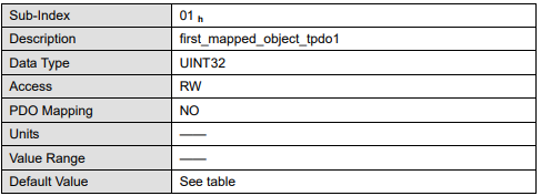
Index =6041 h Subin. = 00h Length = 10 h ⇒ 1st_mapped_object(1A00 h:01 h)= 60410010 h
Index =6061 h Subin. = 00h Length = 08 h ⇒ 2st_mapped_object(1A00 h:02 h)= 60610008 h
Index =60FD h Subin. = 00h Length = 20 h ⇒ 3st_mapped_object(1A00 h:03 h) = 60FD0020 h
3)Set number_of_mapped_objects
number_of_mapped_objects(1A00 h:00 h)= 3
4)Set PDO communication parameter
PDO1(transmit)is asynchronous periodical type ⇒ transmission_type (1800 h:02 h)= FF h
Frozen time 2ms(20×100us) ⇒ inhibit_time (10A0 h:03 h)= 14 h
Period time: 10ms(10×1ms) ⇒ event_time (1800 h:05 h)= 0A h
5)PDO mapping complete.
PDO parameter
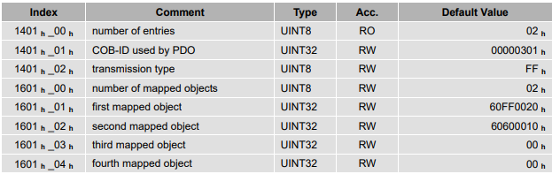
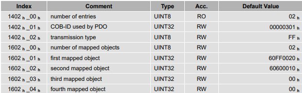
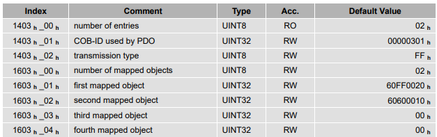
ProNet drive contains 4 transmit PDOs and 4 receive PDOs. The detailed communication parameter and mapping parameter of the first transmit/receive PDO is as below and those of the rest 3 transmit/receive PDO are the same as the first PDO.

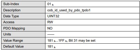
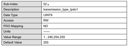

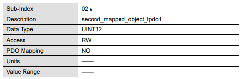

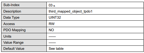
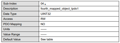
1、T-PDO1
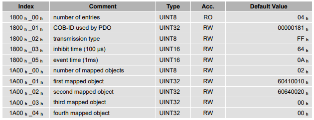
2、T-PDO2
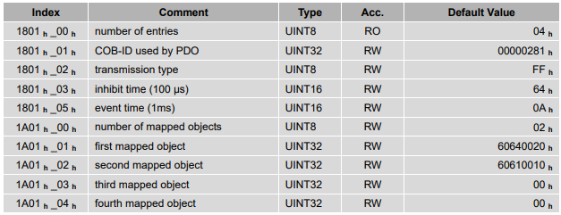
3、T-PDO3
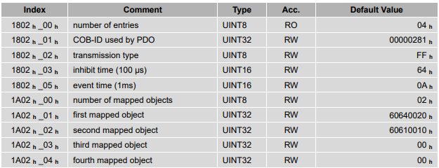
4、T-PDO4
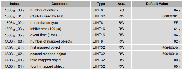
If transmit tye is 254 (if PDO content has changed,trigger will be sent by PDO),using the following object can shield parts of PDO changers.Only when the un-shield bit has changed,PDO is occur.If wants shielding any bit, the corresponding bit of object write to 0.
tpdo_1_transmit_mask

tpdo_2_transmit_mask

tpdo_3_transmit_mask

tpdo_4_transmit_mask

1、R-PDO1
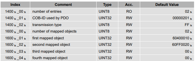
2、R-PDO2
3、R-PDO3
4、R-PDO4
3.4 SYNC message
Synchronization object is used for controlling data synchronize transmit. For example: starting synchronously several axises. The transmition of synchronous message is based on Producer-Customer model. All the nodes of synchronous PDO can receive (at the same time) the message as customer and synchronize other node.
General mode:
CANopen suggests a COB-ID with highest priority to ensure that synchronized signal could be transmitted properly. Without transferring data, SYNC message could be as short as possible.
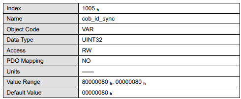
The identifier the servo controller receives SYNC messages are fixed to 080h. The identifier can be read via the object cob_id_sync.
3.5 Emergency message
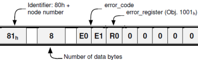
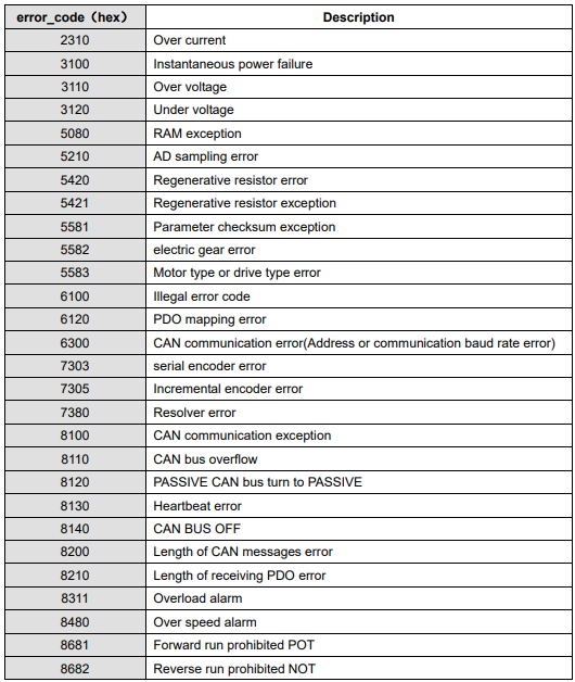
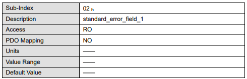
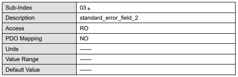
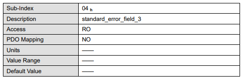
When an alarm occurs to drive, CANopen will initiate an Emergency message to inform the current drive type and error code to clients. Error code displayed on panel can be read on low byte of 603Fh object.
The structure of Emergency message:
Alarm code
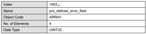
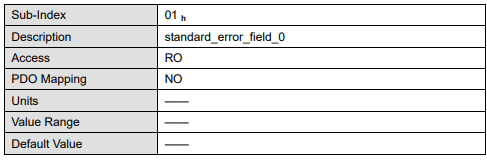
Relevant parameter
3.6 HEARTBEAT message
Structure of the heartbeat message:
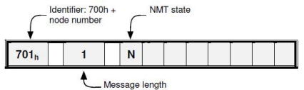
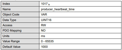
Relevant parameter:
3.7 Network management (NMT service)
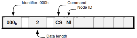
Structure of the message:
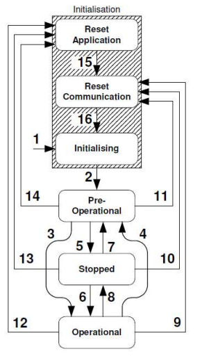
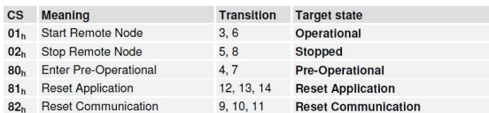
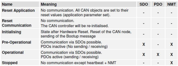
NMT-State machine:
No comments to display
No comments to display