
5. Position control function
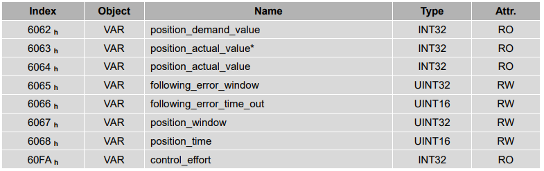
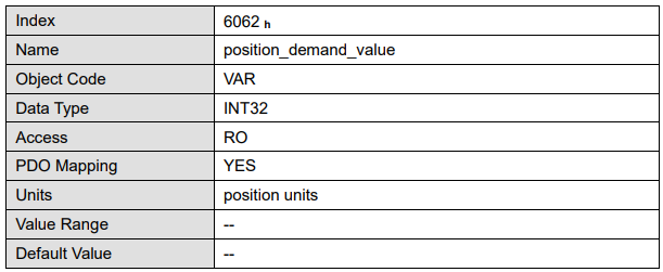
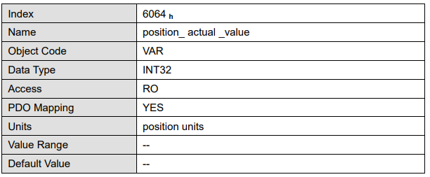
This chapter describes all parameters which are required for the position controller. The desired position value (position_demand_value) of the trajectory generator is the input of the position controller. Besides this the actual position value (position_actual_value) is supplied by the angle encoder (resolver, incremental encoder, etc.). The behaviour of the position controller can be influenced by parameters.
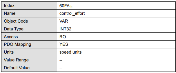
It is possible to limit the output quantity (control_effort) in order to keep the position control system stable. The output quantity is supplied to the speed controller as desired speed value. In the Factor Group all input and output quantities are converted from the application-specific units to the respective internal units of the controller The following subfunctions are defined in this chapter:
1. Trailing error (Following Error)
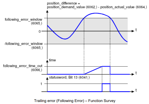
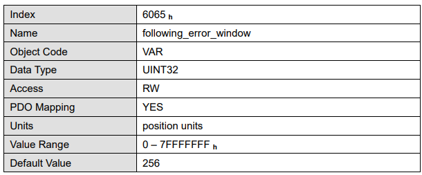
The deviation of the actual position value (position_actual_value) from the desired position value (position_demand_value) is named trailing error. If for a certain period of time this trailing error is bigger than specified in the trailing error window (following_error_window) bit 13 (following_error) of the object statusword will be set to 1.
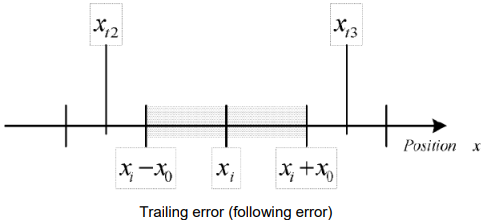
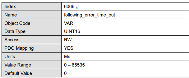
The permissible time can be defined via the object following_error_time_out.。Figure above shows how the window function is defined for the message "following error".The range between xi-x0 and xi+x0 is defined symmetrically
around the desired position (position_demand_value) xi. For example the positions xt2 and xt3 are outside this window (following_error_window). If the drive leaves this window and does not return to the window within the time defined in the object following_error_time_out then bit 13 (following_error) in the statusword will be set to 1.
2. Position Reached
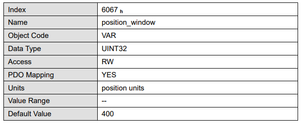
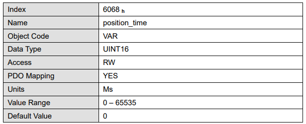
This function offers the chance to define a position window around the target position (target_position). If the actual position of the drive is within this range for a certain period of time – the position_window_time – bit 10 (target_reached) will be set to 1 in the statusword.
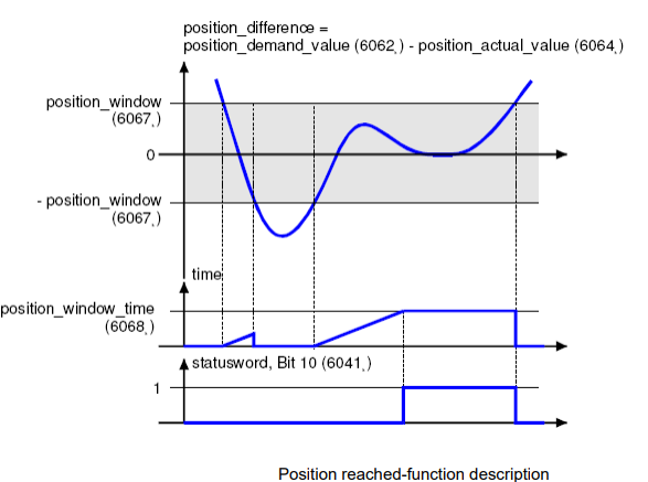
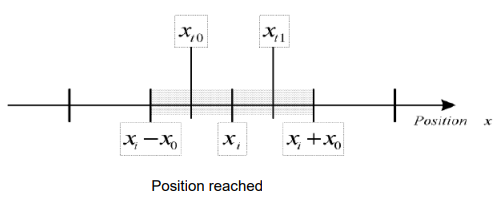
Figure below shows how the window function is defined for the message ”position reached”. The position range between xi-x0 and xi+x0 is defined symmetrically around the target position (target_position) xi. For example the positions xt0 and xt1 are inside this position window (position_window). If the drive is within this window a timer is started. If this timer reaches the time defined in the object position_window_time and the drive uninterruptedly was within the valid range between xi-x0 and xi+x0, bit 10 (target_reached) will be set in the statusword. As far as the drive leaves the permissible range, bit 10 is cleared and the timer is set to zero.
Parameters:
No comments to display
No comments to display