
4. Connector and Cable
This section introduces the device’s connector, including fast Ethernet interface, USB interface and RS-232 interface, and the supplied cable in the package.

4.1 Device with Fast Ethernet Interface
Device with fast Ethernet interface includes type I, type II, type III, type IV, type V, and type VI devices.
Type I, Type II, Type III, and Type IV Devices
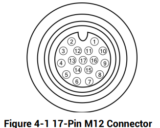
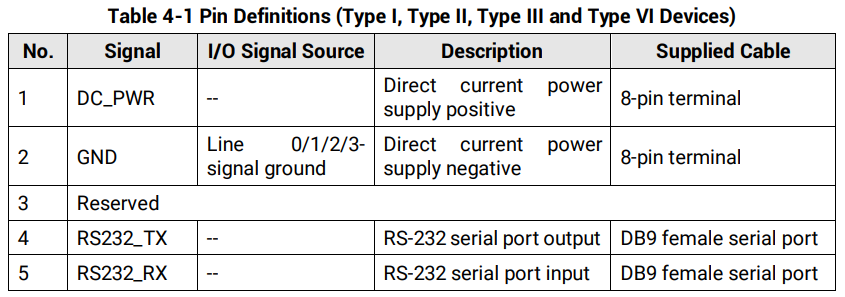
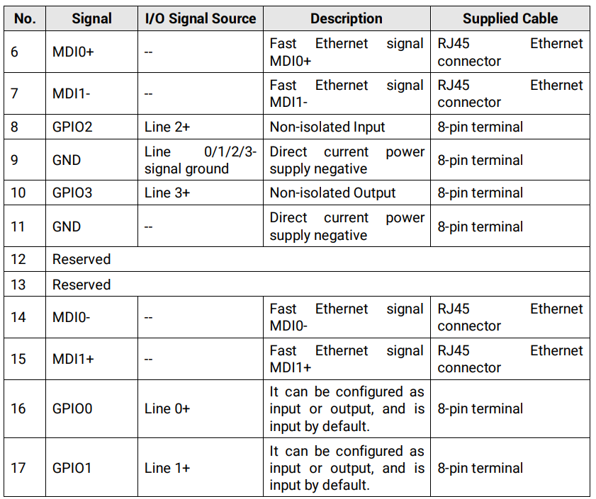
Type I, type II, type III, and type IV devices have a 17-pin M12 connector. Refer to the figure and table below for details.
Type V Devices
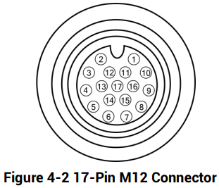
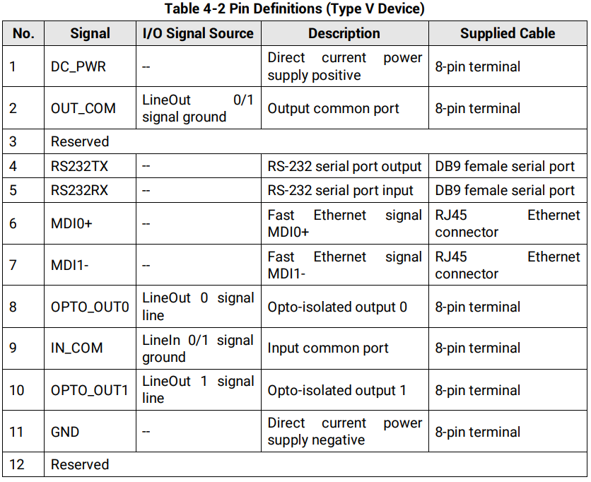
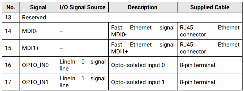
The type V device also has a 17-pin M12 connector. Refer to the figure and table below for details.
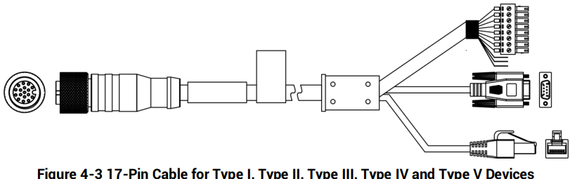
For type I, type II, type III, type IV, and type V devices, you should use the supplied 17-pin cable below to wire them. The cable has a DB9 female serial port connector that corresponds to 4th and 5th pins of the 17-pin M12 connector, and a RJ45 connector that corresponds to 6th, 7th, 14th, and 15th pins of the 17-pin M12 connector. Others lines of the 17-pin cable have been made into an 8-pin terminal.
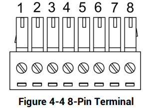
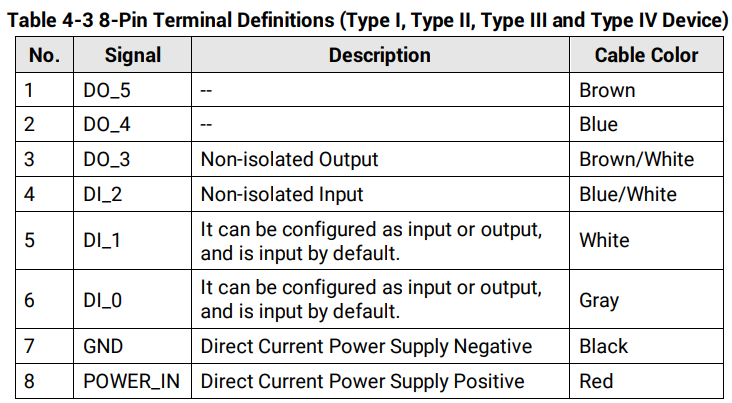
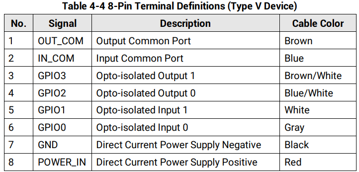
The 8-pin terminal is shown below. Refer to table 4-3 for the type I, type II, type III and type IV devices’ pin definitions, and refer to table 4-4 for the type V device’s pin definitions.

Type VI Device
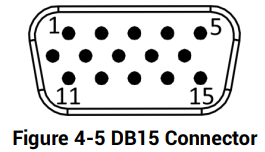
Type VI device has a DB15 connector. Refer to the figure and table below for connector pin definitions.
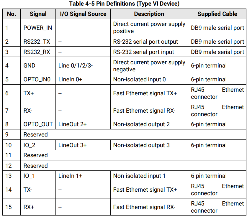
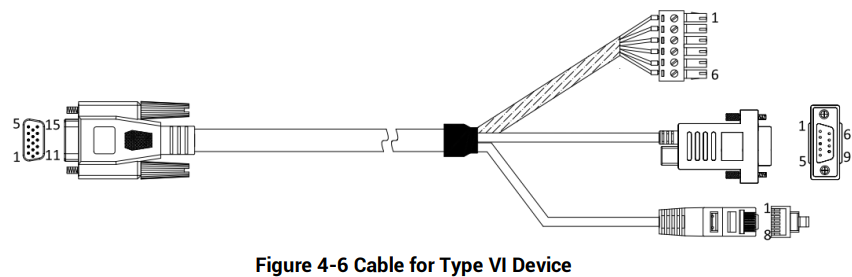
For type VI device, you should use the supplied cable, as shown below, to wire the device. The cable has a DB9 female serial port that corresponds to 1st, 2nd, and 3rd pins of the device’s DB15 connector, and a 6-pin terminal that corresponds to 4th, 5th, 8th, 10th, and 13th pins of the device’s DB15 connector, and a RJ45 connector that corresponds to 6th, 7th, 14th, and 15th pins of the device’s DB15 connector.
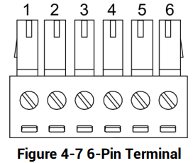
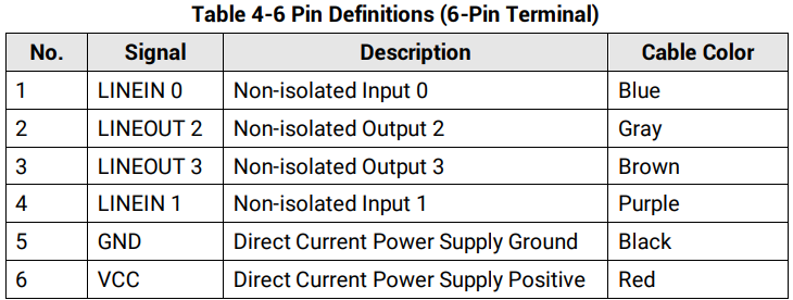
Refer to the figure and table below for the pin definitions of the 6-pin terminal.

4.2 Device with USB Interface
Device with USB interface includes type I device to type VII device.
Type I to Type V Devices
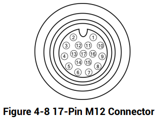
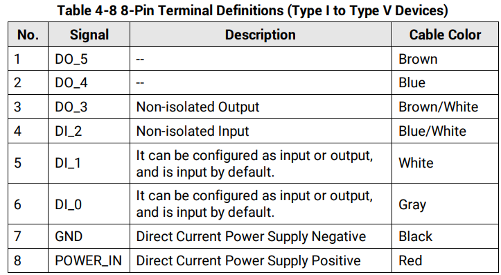
Type I, type II, type III, type IV and type V devices all have a 17-pin M12 connector. Refer to the figure and table below for connector pin definitions.
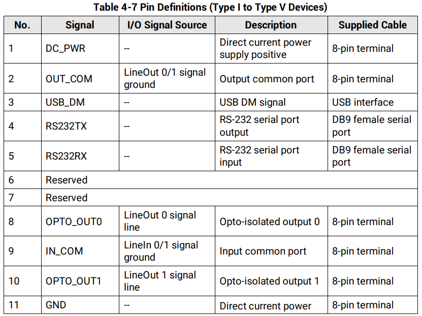
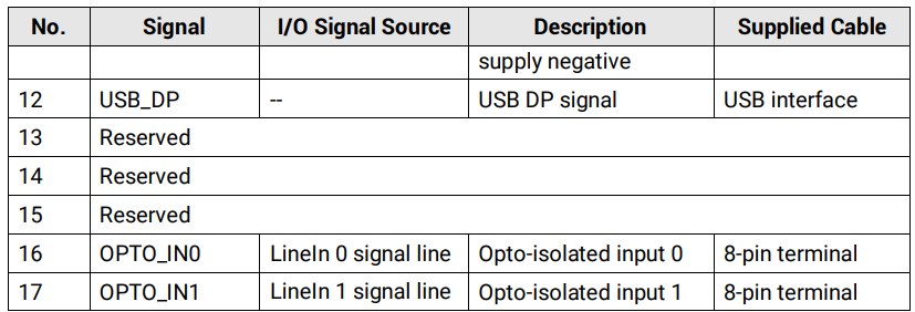
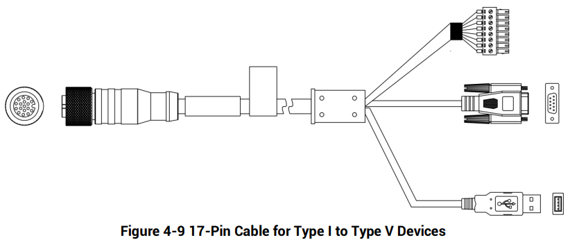
For type I to type V devices with USB interface, you should use the supplied 17-pin cable below to wire them. The cable has a DB9 female serial port connector that corresponds to 4th and 5th pins of the 17-pin M12 connector, and a USB interface that corresponds to 3th and 12th pins of the 17-pin M12 connector. Others lines of the 17-pin cable have been made into an 8-pin terminal.
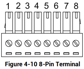
Refer to the figure and table below for the pin definitions of the 8-pin terminal.

Type VI Device
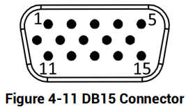
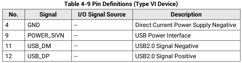
Type VI device has a DB15 connector. Refer to the figure and table below for connector pin definitions.
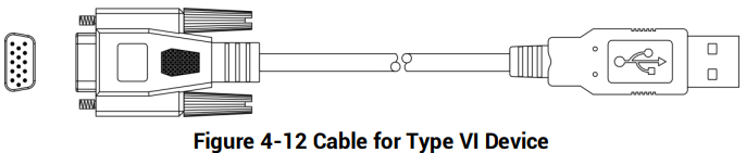
For type VI device, you should use the supplied cable, as shown below, to wire the device. The cable has a 15-pin connector for connecting with the device, and a USB interface for connecting with the PC.
Type VII Device
Type VII device with USB interface has a cable with 10-pin RJ45 female connector. It is recommended to use the supplied cable, as shown below, in the package when using the device. The supplied cable has a RJ45 male connector for connecting the device, and a USB interface for connecting external devices.
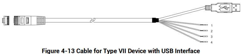
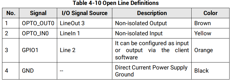
The supplied cable also has four open lines with different colors, and you can wire them according to actual demands.
4.3 Device with RS-232 Interface
Type VII device with RS-232 interface has a cable with 10-pin RJ45 female connector. It is recommended to use the supplied cable, as shown below, in the package when using the device. The supplied cable has a RJ45 male connector for connecting the device, and a DB9 interface for connecting external devices.
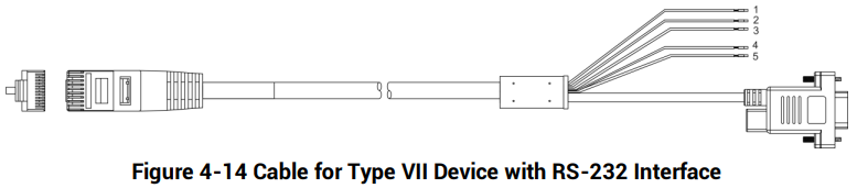
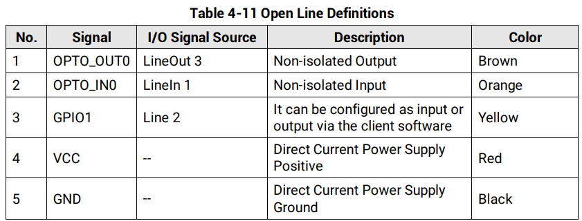
The supplied cable also has five open lines with different colors, and you can wire them according to actual demands.

4.4 IO Box
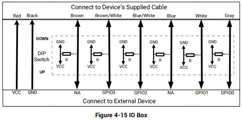
You can use IO box to connect NPN/PNP devices to access to pull-up and pull-down resistors.
● ID2000 series industrial code reader: You should use the supplied cable to connect the code reader to the top terminal of the IO box.
● External devices: You should connect external devices to the bottom terminal of the IO box.
● Pull-up and pull-down resistors: if the DIP switch is switched to DOWN, pull-down resistor is connected. If the DIP switch is switched to UP, pull-up resistor is connected.

No comments to display
No comments to display