
6. I/O Electrical Feature and Wiring
6.1 I/O Electrical Feature and Wiring of Type V Device
6.1.1 Opto-isolated Input Circuit
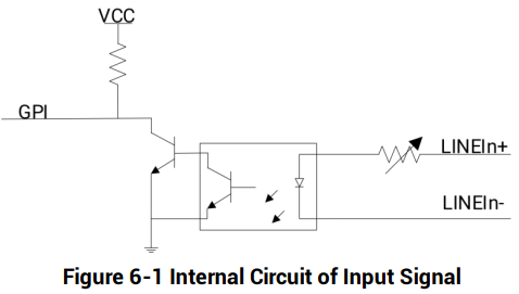
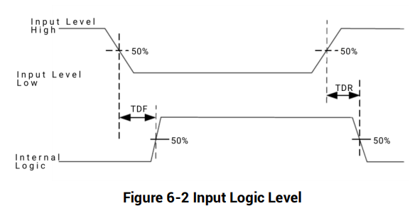
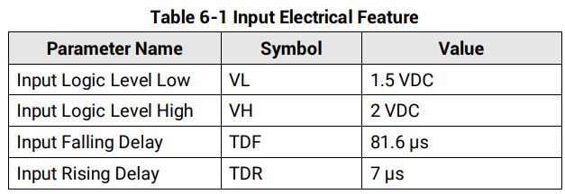
Type V device's LineIn 0/1 are opto-isolated inputs, and internal circuit is as follows.

6.1.2 Opto-isolated Output Circuit
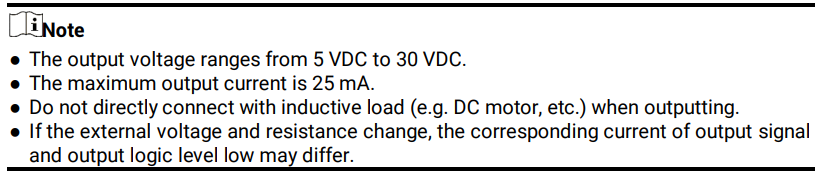
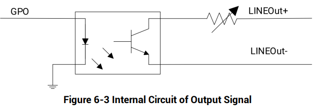
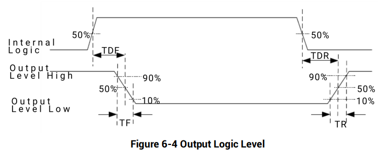
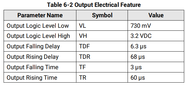
Type V device's LineOut 0/1 are opto-isolated outputs, and internal circuit is as follows.
6.1.3 Input Signal Wiring
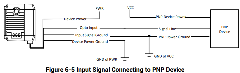
The device can receive the external input signal, and this section introduces input signal wiring.

PNP Device
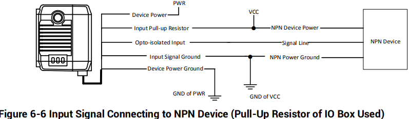
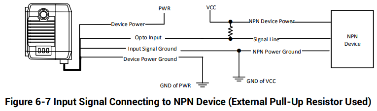
NPN Device
If the VCC of NPN device is 12 VDC or 24 VDC, and the pull-up resistor of the IO box is used.
If the VCC of NPN device is 12 VDC or 24 VDC and the external pull-up resistor is used, it is recommended to use 1 KΩ pull-up resistor.
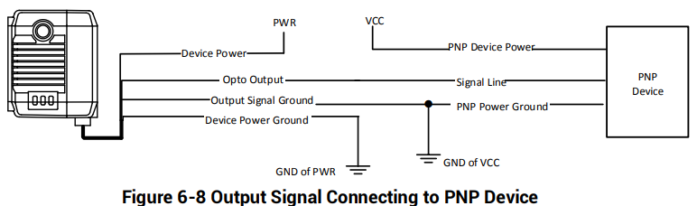
6.1.4 Output Signal Wiring

PNP Device
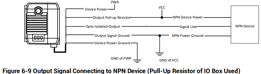
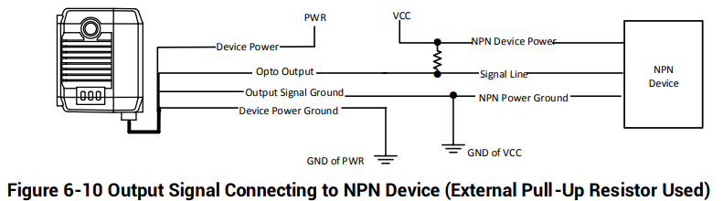
NPN Device
If the VCC of NPN device is 12 VDC or 24 VDC, and the pull-up resistor of the IO box is used.
If the VCC of NPN device is 12 VDC or 24 VDC and the external pull-up resistor is used, it is recommended to use 1 KΩ pull-up resistor.
6.2 I/O Electrical Feature and Wiring of Other Devices
The other devices include type I to type IV devices, and type VI and type VII devices. With different device types, their I/O electrical feature varies.
● Type II device: Its Line 0/1/2/3 are all bi-directional signals.
● Type I, type III, type IV and type VI devices: Their Line 2 is non-isolated input signal, Line 3 is non-isolated output signal, and Line 0/1 are both bi-directional signals.
● Type VII device: Its LineIn 1 is non-isolated input signal, LineOut 3 is non-isolated output signal, and Line 2 is bi-directional signal.
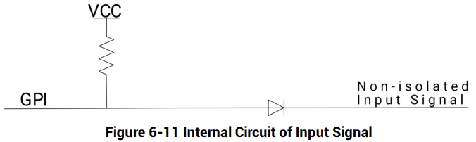
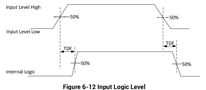
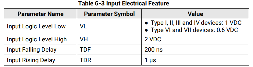
6.2.1 Non-isolated Input Circuit
The internal circuit of other devices’ non-isolated input signal is as follows.
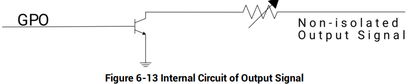
6.2.2 Non-isolated Output Circuit
The internal circuit of the device’s non-isolated output signal is as follows.
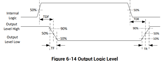
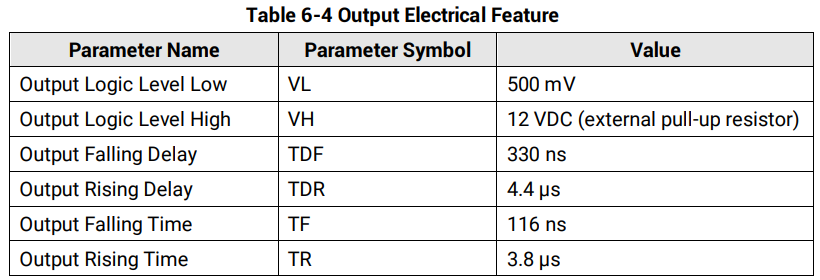
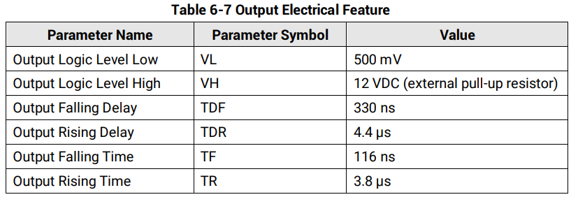
When the external voltage is 12 VDC and pull-up resistor is 1 KΩ, output electric feature is shown below.
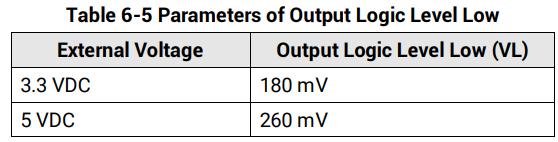
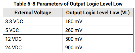
Relation between different external voltages and output logic level low is shown below.
6.2.3 Bi-directional I/O Circuit
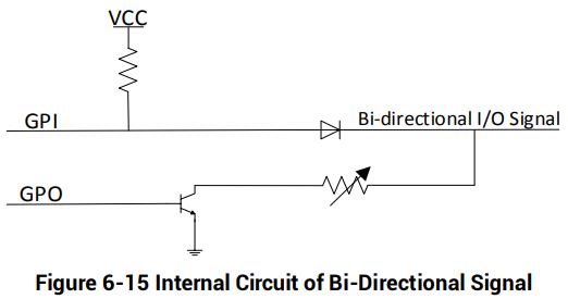
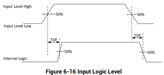
The bi-directional signal in I/O signal can be use as input signal or output signal according to demands. Its internal circuit is shown below.
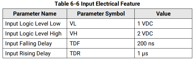
Configured as Input Signal
Configured as Output Signal
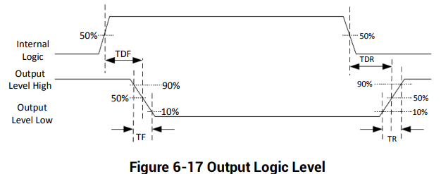
When the external voltage is 12 VDC and pull-up resistor is 1 KΩ, output electric feature is shown below.
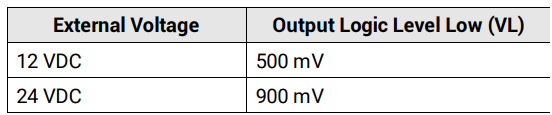
Relation between different external voltages and output logic level low is shown below.
6.2.4 Input Signal Wiring
The device can receive the external input signal, and this section introduces input signal wiring.

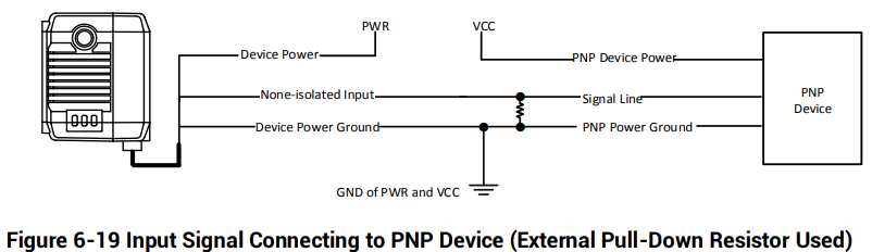
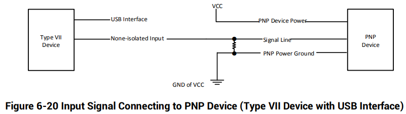
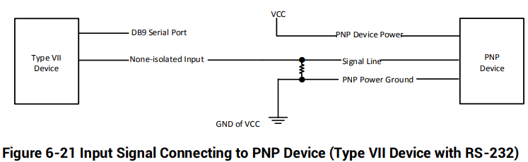
PNP Device
Other devices apart from type VII device use the pull-down resistor of the IO box, the wiring is shown below.
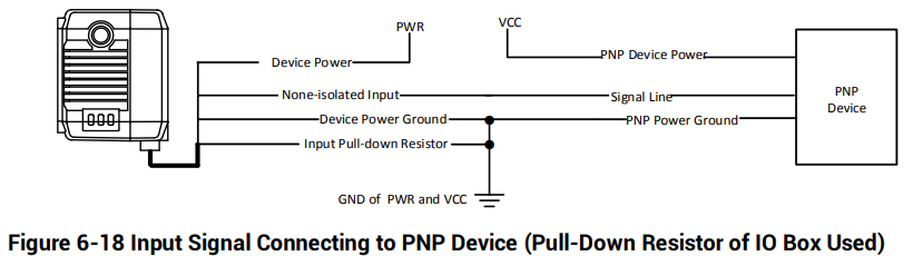
Other devices apart from type VII device use external pull-down resistor, it is recommended to use 1 KΩ pull-down resistor.
Type VII device uses external pull-down resistor, it is recommended to use 1 KΩ pull-down resistor.
NPN Device
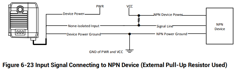
Other devices apart from type VII device use the pull-up resistor of the IO box, the wiring is shown below.
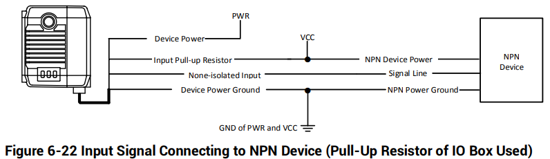
Other devices apart from type VII device use external pull-up resistor, it is recommended to use 1 KΩ pull-up resistor.
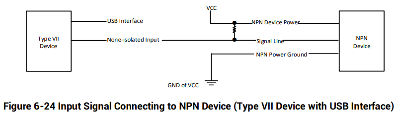
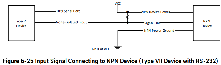
Type VII device uses external pull-up resistor, it is recommended to use 1 KΩ pull-up resistor.
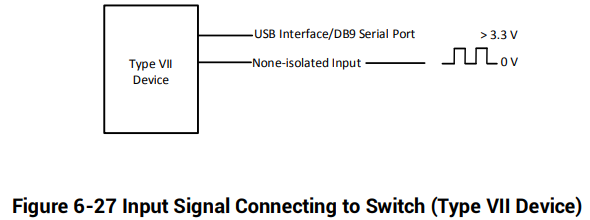
Switch
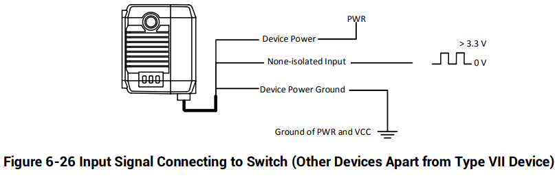
The switch can provide low electrical level to trigger the bi-directional I/O.
6.2.5 Output Signal Wiring

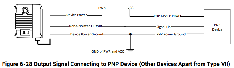
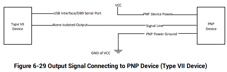
PNP Device
NPN Device
Other devices apart from type VII device use the pull-up resistor of the IO box, the wiring is shown below.
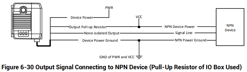
Other devices apart from type VII device use external pull-up resistor, it is recommended to use 1 KΩ pull-up resistor.
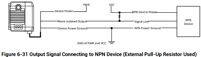
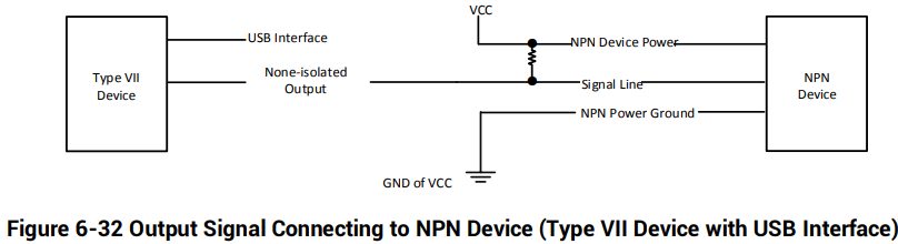
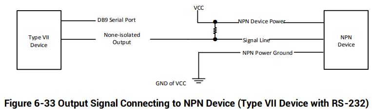
Type VII device uses external pull-up resistor, it is recommended to use 1 KΩ pull-up resistor.
6.3 RS-232 Serial Port
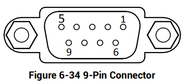
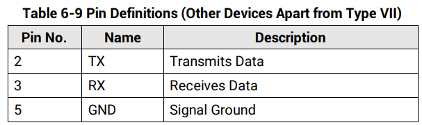
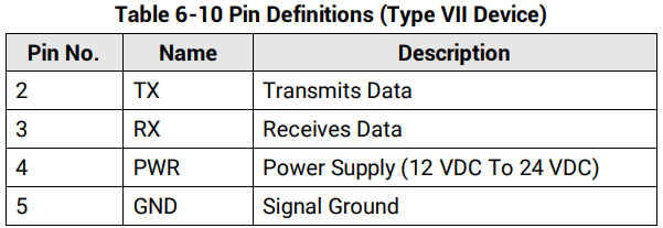
The device supports outputting data via RS-232 serial port, and the supplied cable has a 9- pin female serial port connector. Refer to the figure and table below for pin definitions.

No comments to display
No comments to display