
3. Wiring and Connecting
3.1 Precautions for Wiring
3.1.1 General Precautions
3.1.2 Countermeasures against Noise

Since the Drive uses microprocessors, it may be affected by switching noise from peripheral devices.
To prevent the noise from the Drive or the peripheral devices from causing malfunctions of any devices, take the following countermeasures against noise as required.
Install the input reference device and Noise Filter as close to the Drive as possible.
Always install a Surge Absorber for relays, solenoids, and Magnetic Contactor coils.
Never place the following cables in the same duct or bundle them together. Also, separate the cables from each other by at least 30 cm.
- Main Circuit Cables and I/O Signal Cables
- Main Circuit Cables and Encoder Cables
Never share the power supply with an electric welder or electrical discharge machine. If the Drive is placed near a high-frequency generator, install Noise Filters on the input side on the Main Circuit Power Supply Cable and Control Power Supply Cable even if the same power supply is not shared with the high-frequency generator. Refer to the section Noise Filters for information on connecting Noise Filters.
Implement suitable grounding measures. Refer to the section 3.1.4 Grounding for information on grounding measures.
Noise Filters
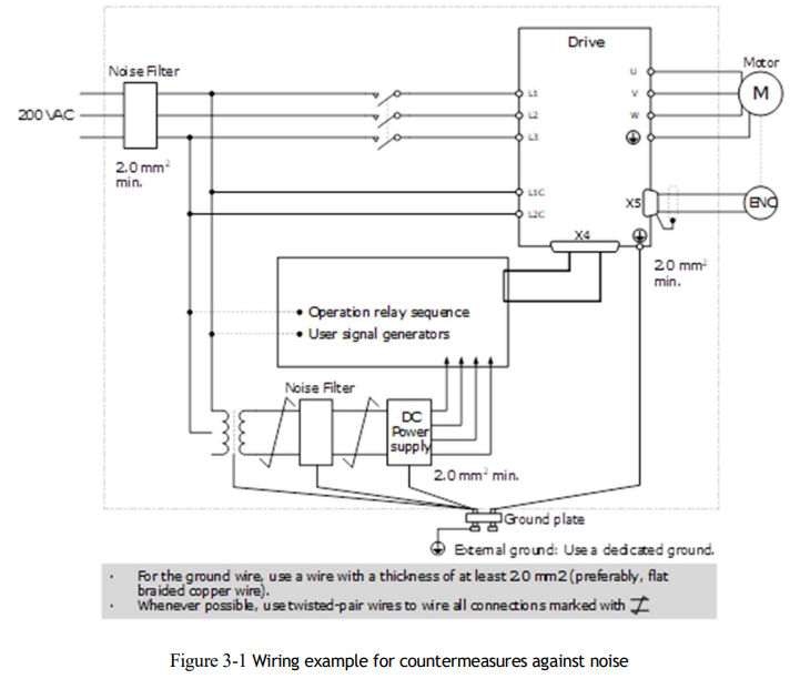
You must attach Noise Filters in appropriate places to protect the Drive from the adverse effects of noise. Figure 3-1 is an example of wiring for countermeasures against noise.
Noise Filter Wiring and Connection Precautions
Always observe the following precautions when wiring or connecting Noise Filters.
Separate input lines from output lines. Do not place input lines and output lines in the same duct or bundle them together.
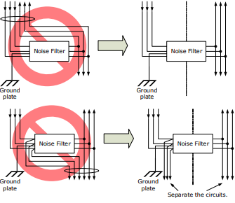
Separate the Noise Filter ground wire from the output lines. Do not place the Noise Filter ground wire, output lines, and other signal lines in the same duct or bundle them together.
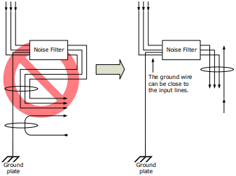
Connect the Noise Filter ground wire directly to the grounding plate. Do not connect the Noise Filter ground wire to other ground wires
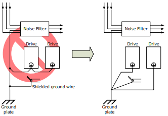
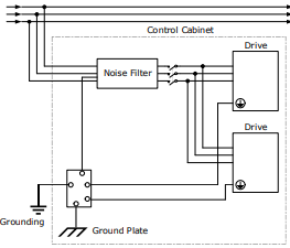
If a Noise Filter is located inside a control panel, first connect the Noise Filter ground wire and the ground wires from other devices inside the control panel to the grounding plate for the control panel, then ground the plate.
3.1.3 Recommended EMC Filters
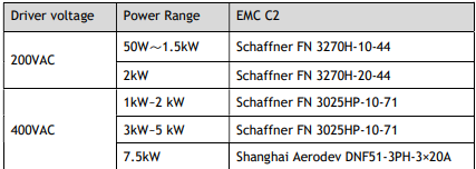
To comply with the limits based on IEC/EN 61800-3 second environment (C2) the Drive and Motor must be installed with an EMC/RFI filter. Recommended filters are:

3.1.4 Grounding
Implement grounding measures as described in this section. Implementing suitable grounding measures will also help prevent malfunctions, which can be caused by noise. Always use an unpainted backplane for electrical cabinets.
Observe the following precautions when wiring the ground cable.
Ground the Drive to a resistance of 100 mΩ or less.
Be sure to ground at one point only.
Ground the Motor directly if the Motor is insulated from the machine.
Motor Frame Ground or Motor Ground
If the Motor is grounded thought the machine, the switching noise current can flow from the main circuit of the Drive through the stray capacitance of the Motor. To prevent this always connect the Motor frame terminal (FG) or ground terminal (FG) of the Motor to the ground terminal on the Drive. Also, be sure to ground the ground terminal .
Noise on I/O Signal Cables
To prevent noise entering the I/O Signal Cable connect the shield of the I/O Signal Cable to the connector shell and ensure the shell is connected to ground.
If placing cables in metal conduits, ensure the conduit is connected to ground.
For all grounding, use a single grounding point.
Cable Fixing
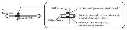
It is recommended that all cable shields are secured with a conductive metal clamp to the ground plate.
For example:
Ferrite Coils
While ferrite coils can be used to solve application specific EMC issues, they should not be necessary for applications.
3.2 Basic Wiring Diagrams
Rated power from 50W to 400W (200VAC)
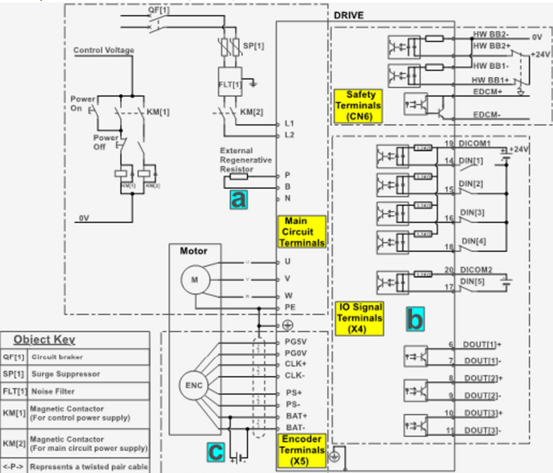
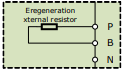
a. When an external discharge resistor is required, an external regenerative resistor is connected between P and B.
The connection method is as follows. In addition, check and set "Pn521.0=0".
b. The external wiring of the input signals can use the co-cathode method or the co-anode method.
c. The connection of the battery is only for the Motors with the absolute encoder.
Rated power from 750W to 2kW (200VAC)
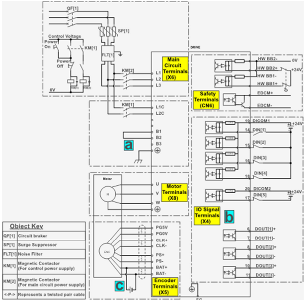
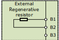
a. When the busbar capacitance is insufficient, remove the short wiring between B2 and B3, and connect an external regenerative resistor between B1 and B2, as is shown in the following figure. In addition, check and set Pn521.0 as 0 after the power up.
b. The external wiring of the input signals can use the co-cathode method or the co-anode method.
c. The connection of the battery is only for the Motors with the absolute encoder.
Rated power from 1kW to 3kW (400VAC)
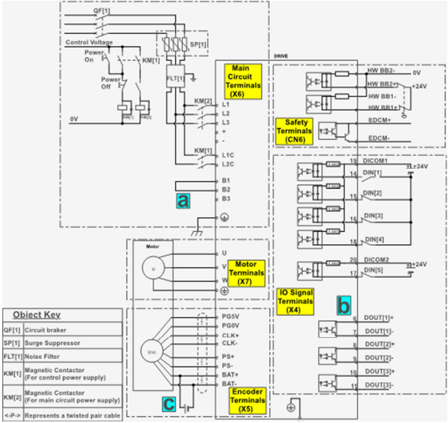
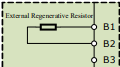
a. When an external bleeder resistor is required, remove the jumper between B2 and B3 and connect an external regenerative resistor between B1 and B2, as shown below. In addition, check and set “Pn521.0=0”.
b. The input signal can be wired with a common cathode or common anode.
c. Only servo motors with absolute encoders use the battery case wiring.
Rated power from 5kW to 7.5kW (400VAC)
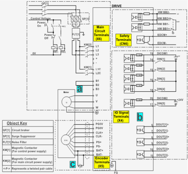
a. When an external bleeder resistor is required, remove the jumper between B2 and B3 and connect an external regenerative resistor between B1 and B2, as shown below. In addition, check and set “Pn521.0=0”.
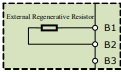
b. The input signal can be wired with a common cathode or common anode.
c. Only servo motors with absolute encoders use the battery case wiring.
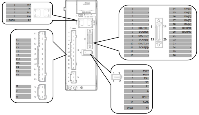
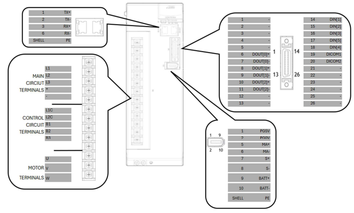
3.3 Terminals Arrangements
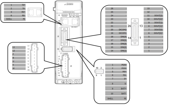
Rated power from 50W to 400W (200VAC)
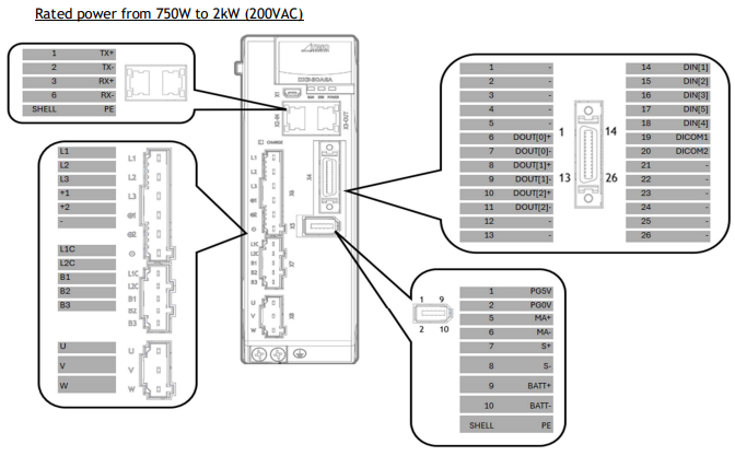
Rated power from 1kW to 1.5kW (400VAC)
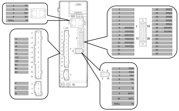
Rated power from 2kW to 3kW (400VAC)
Rated power from 5kW to 7.5kW (400VAC)
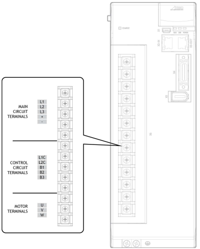
3.4 Wiring the Power Supply to Drive
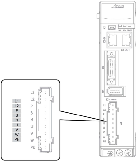
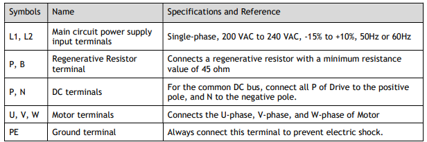
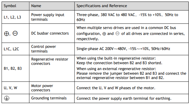
3.4.1 Terminals Arrangement
Rated power from 50W to 400W (200VAC)
Rated power from 750W to 1kW (200VAC)
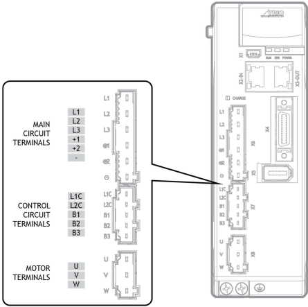
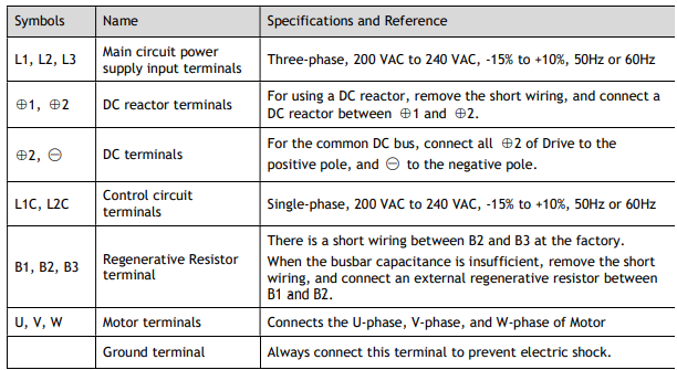
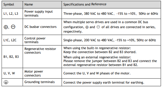
Rated power from 1kW to 3kW (400VAC)
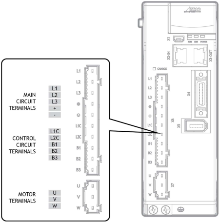
Take for example a product with a power rating of 1kW~1.5kW. Products with power rating from 1.5kW to 3kW are similar in appearance and have the same components.
Rated power from 5kW to 7.5kW (400VAC)

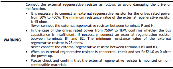
3.4.2 Wiring a Regenerative Resistor
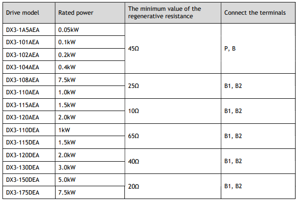
When the busbar capacitance is insufficient, the driver needs an external regenerative resistor. The minimum resistance of a regenerative resistor varies by driver model, and the detailed specifications are shown in the table below.
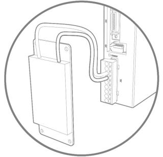
The image below is an example of connecting an external regenerative resistor for the drives rated power from 50W to 400W.
Connect an external regenerative resister between terminals P and B.
3.4.3 Wiring Procedure
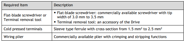
Prepare the following items before preparing the wiring for the Main Circuit Terminals and Control Circuit Terminals.
Follow the procedure below to wire the Main Circuit Terminals and Control Circuit Terminals.
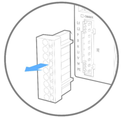
Step 1 Remove the Main Circuit Terminals and Control Circuit Terminals from the Drive.
Step 2 Peel off the sheath so that the conductor portion of the cable will protrude from the tip of the ferrule.

Step 3 Insert the cable into the ferrule (It should protrude 1 mm or more from the ferrule).
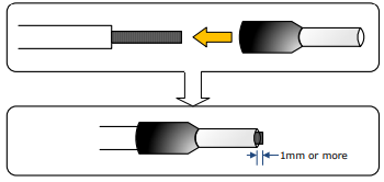
Step 4 Crimp the cable that has been inserted into the ferrule and cut off the cable conductor portion protruding from the ferrule (The allowable protruding length after cutting should not be more than 0.5 mm).

Step 5 Use the flat-blade screwdriver or the terminal removal tool to press down the spring button corresponding to the terminal and then insert the cable.
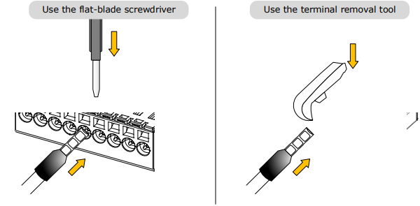
Step 6 Insert the crimped cable into the connection terminals and then pull out the tool.
Step 7 Make all other connections in the same way.
Step 8 To change the wiring, pull the cable out of the connection terminals.
Use the flat-blade screwdriver to press down the spring button corresponding to the terminal, and then gently pull out the cable.
Step 9 When you have completed wiring, attach connection terminals to the Drive.

----End
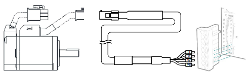
3.4.4 Motor Connection Diagram
3.4.5 Motor Power Cable Description
See table in section 1.8 Part Numbers for details of power cables for specific motor part numbers.
3.4.6 Motor Power Input Wiring Specifications
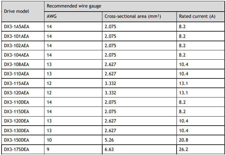
The power input wiring specification depends on the Motor model. The following table shows the recommended wire gauge for each Drive.
3.4.7 Power Input Wiring Example
Rated power from 50W to 400W (200VAC)
Single-phase 200 VAC to 240 VAC
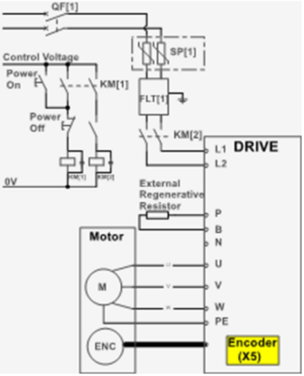
QF[1]: Circuit breaker SA[1]: Surge Absorber 1 FLT[1]: Noise Filter
Ry[1]: Relay
KM[1]: Magnetic Contactor (for control power supply)
KM[2]: Magnetic Contactor (for main circuit power supply)
Rated power from 750W to 2kW (200 VAC)
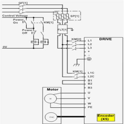
Three-phase 200 VAC to 240 VAC (Single-phase can be used up to 1.5kW)
The following figure shows the wiring example for using the three-phase AC input power.
The following figure shows the wiring example for using the single-phase AC input power.
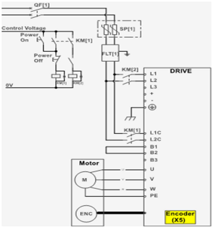
QF[1]: Moulded-case circuit breaker SA[1]: Surge Absorber 1 FLT[1]: Noise Filter
Ry[1]: Relay
KM[1]: Magnetic Contactor (for control power supply)
KM[2]: Magnetic Contactor (for main circuit power supply)
Rated power from 1kW to 7.5kW (400 VAC)
Three-phase AC 380 VAC to 480 VAC.
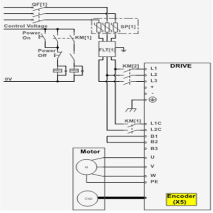
QF[1]: Moulded-case circuit breaker SA[1]: Surge Absorber 1 FLT[1]: Noise Filter
Ry[1]: Relay
KM[1]: Magnetic Contactor (for control power supply)
KM[2]: Magnetic Contactor (for main circuit power supply)
3.5 Wiring the Encoder
3.5.1 Connection Diagram
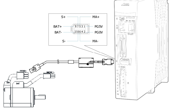
3.5.2 Encoder Cable Description
The encoder cable depends on the Motor model. See table in section 1.8 Part Numbers for details of encoder cables for specific motor part numbers.
3.5.3 Battery Case Connection

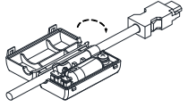
Follow the instructions below to install or replace the battery case.
Step 1 Turn ON only the control power supply to the Drive.
Step 2 Open the cover of the battery case.
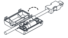
Step 3 Remove the old battery and mount a new battery.
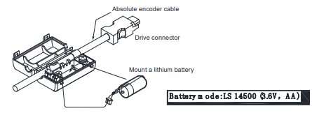
Step 4 Close the cover of the battery case.
Step 5 Repower up the Drive.
Step 6 Reset the Alarms.

Step 7 Make sure the alarms have been cleared, and the Drive operates normally.
----End
3.6 I/O Signal Connections
3.6.1 Signal Diagram
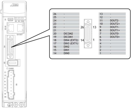

3.6.2 Pin Layout
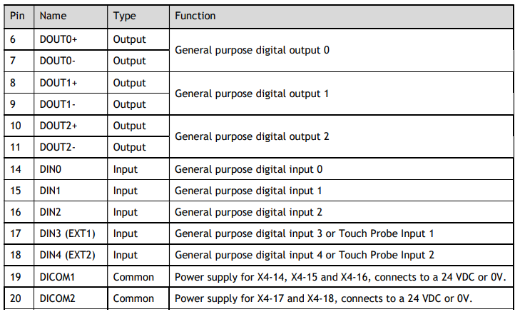
3.6.3 Wiring Description
Input Signals Wiring
The input signals of the Drive are divided into two groups, and the details are as shown in the table below.
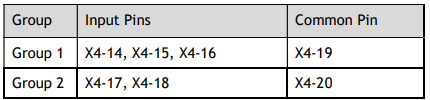

Figure 3-2 shows the connection diagram using an external 24 VDC power supply. The example below shows P-OT as the input pin.
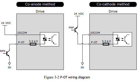
Functionality can be assigned to the input signals using Pn509 and Pn510:
TP (Touch Probe)
S-ON (Servo ON)
P-OT (Forward Drive Prohibit)
N-OT (Reverse Drive Prohibit)
P-CL (Forward External Torque Limit)
N-CL (Reverse External Torque Limit)
G-SEL (Gain Selection)
HmRef (Homing)
Remote (Controlled from EtherCAT - default)
For the input signal allocation, see the section 6.8.1 Input Signal Allocations.
Output Signals Wiring
Figure 3-3 shows the connection diagram to an optocoupler or relay. The example below shows TGON as the output pin.
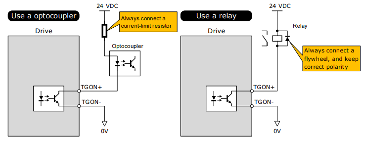
The maximum permissible voltage and current of the optocoupler output circuit inside the servo drive are as follows:
Maximum voltage: 30 VDC
Maximum current: DC 50 mA
Functionality can be assigned to the output signals by using Pn511:
COIN/VCMP (Positioning Completion or Speed Coincidence Detection)
TGON (Rotation Detection)
S-RDY (Servo Ready)
CLT (Torque Limit Detection)
BK (Brake)
PGC (Motor C-pulse)
OT (Overtravel)
RD (Motor Excitation)
TCR (Torque Detection)
Remote (Controlled by EtherCAT - default)
For the output signal allocation, see the section 6.8.2 Output Signal Allocations.
3.6.4 Holding Brake Wiring
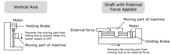
A holding brake is used to hold the position of the moving part of the machine when the Drive is turned OFF so that the moving part does not move due to gravity or an external force.
You can use the brake that is built into a Motor with a Brake, or you can provide one on the machine. The holding brake is used in the following cases.
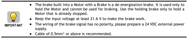
An Interposing relay must be used to control the supply to the motor brake coil. The motor power cable with the brake option selected will have two spare coloured cores ready for external holding brake control. The two cores are White and Green and connection to the brake is not polarity sensitive, both cores may be connected to either +24Vdc or 0V.
Taking the drives rated from 50W to 400W as an example, Figure 3-4 shows the connection diagram of the holding brake.
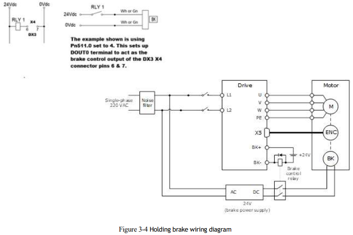
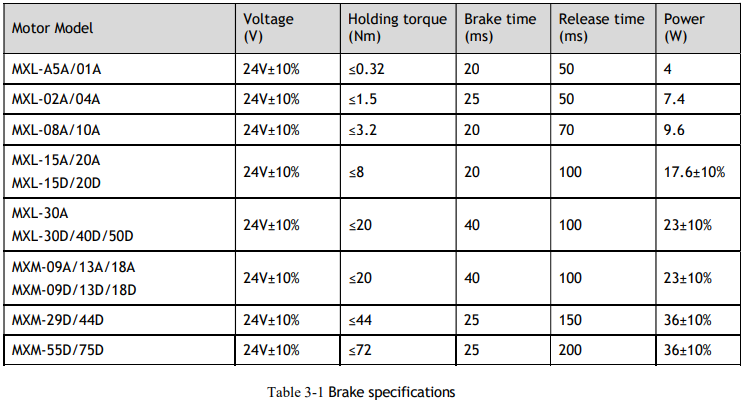
Table 3-1 lists brake specifications for each Motor matched with DX3.
3.6.5 Touch Probe Wiring
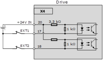
You shall only use the terminals X4-17 and X4-18 for Touch Probe input signal, which has been allocated at factory. The following figure shows the example diagram for the connection.
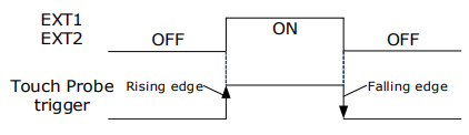
The timing sequence between input signals and trigger is as shown below.

3.7 Communication Connections
3.7.1 EtherCAT Communication
Connection Diagram
Pin Layout
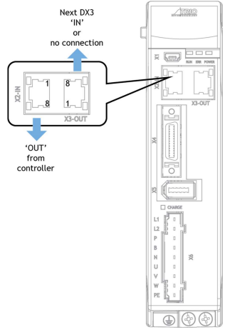
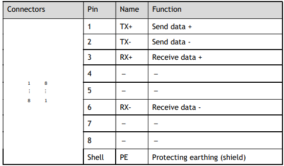
EtherCAT communication (X2-IN and X3-OUT) are RJ45 terminals. The communication cable as the master station or controller should be connected from X2-IN, and X3-OUT should be connected to the X2-IN terminal of the next Drive (slave station).
Cable Description
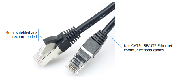
Use category 5 (CAT5e SF/UTP) Ethernet communications cables for network connections. Metal shielded connectors are recommended to prevent signal interference.
3.7.2 USB Communication Cable
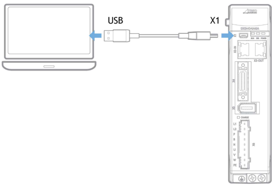
Connects your PC to a Drive with a USB Communication Cable in order to make the online operation of Motion Perfect V5.3 or above.
Connection Diagram
Cable Description
You can purchase the USB Communication Cable provided by Trio, or you can purchase the commercially available products yourself.
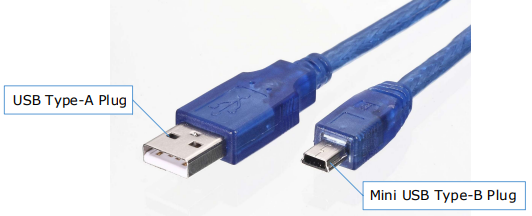
The plug connected to your PC is USB Type-A, and the plug connected to the Drive is Mini USB Type B.
No comments to display
No comments to display