
7. EtherCAT Communications
7.1 Introduction
EtherCAT is a real-time Industrial Ethernet technology originally developed by Beckhoff Automation. The EtherCAT protocol which is disclosed in the IEC standard IEC61158 is suitable for hard and soft real-time requirements in automation technology, in test and measurement and many other applications.
The EtherCAT master sends a telegram that passes through each node. Each EtherCAT slave device reads the data addressed to it “on the fly” and inserts its data in the frame as the frame is moving downstream. The frame is delayed only by hardware propagation delay times. The last node in a segment (or drop line) detects an open port and sends the message back to the master using Ethernet technology’s full duplex feature.
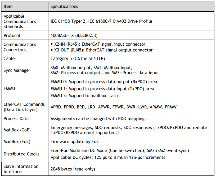
7.2 Specification
7.3 Communication Indication
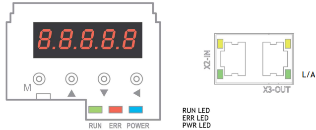
There are 3 indicator lamps on the panel Operator of the Drive to indicate the communication status of EtherCAT: RUN and ERR.
In addition, X2-IN and X3-OUT connectors has L/A indicators.

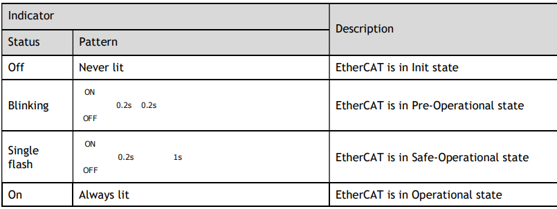
RUN Indicator
The RUN indicator shows the status of EtherCAT communications.
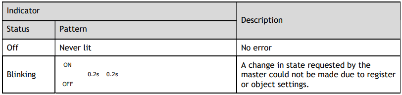
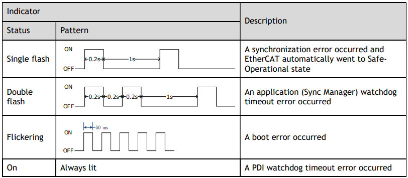
ERR Indicator
The ERR indicator shows the error status of EtherCAT communications.
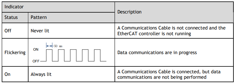
LINK/ACT Indicator
The LINK/ACT indicators show whether Communications Cables are connected to the X2-IN and X3-OUT connectors and whether communications are active.
7.4 EtherCAT Slave Information
The drive publishes network accessible properties via an EtherCAT Slave Information (ESI) file. This is an MXL based file which is used by the network master.
The ESI file for the DX3 Drive can be found on the official website of Trio and has the name: DX3_V1.****.xml
NOTE: The asterisks (***) indicate the version number.
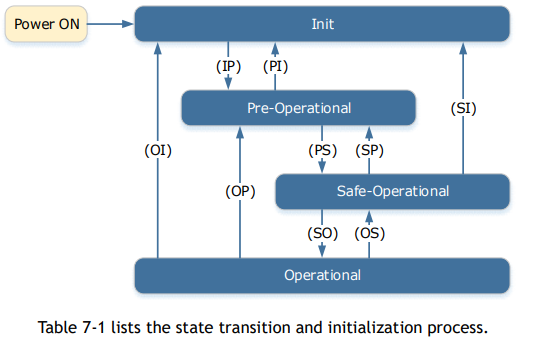
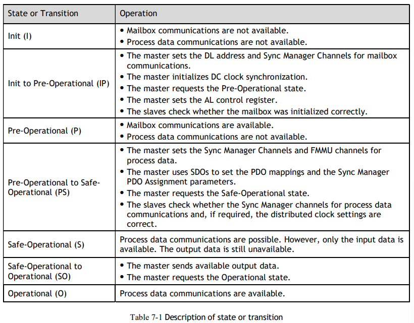
7.5 EtherCAT State Machine
A state machine is used to manage the communications states between the master and slave applications, shown in following figure. Normally, the state of the slave responds based on requests from the master.
7.6 Communications between Master and Slave
PDO
PDO is used to transfer cyclic data. This is data that is transferred between the master and slave every network cycle. Typically, this is data required for operation of the drive; Control Word, Status Word, Set Point, etc.
SDO
SDO is used to transfer non-cyclic data, such as communication parameter configuration, and Servo running parameter configuration. The CoE service type includes Emergency Message, SDO request and SDO response.
Emergency Message
When an alarm occurs in the Drive, the CoE service can trigger an emergency message to inform the user of the error code. The Motion Coordinator response to the emergency message can be set by the ECAT_MODE system parameter in the controller.
Distributed Clock
The synchronization of EtherCAT communications is based on a mechanism called a distributed clock. With the distributed clock, all devices are synchronized with each other by sharing the same reference clock. The slave devices synchronize the internal applications to the Sync0 events that are generated according to the reference clock.
The figure below shows a timing chart for DC synchronization.
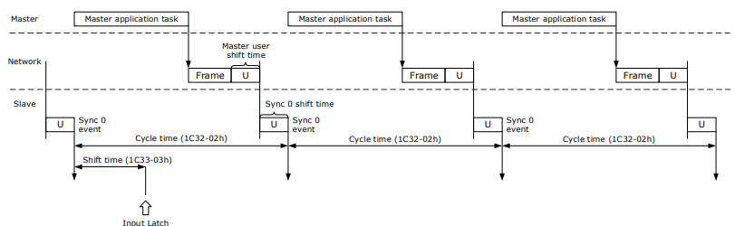
NOTE: Only the object 1C33-03h can be set.
7.7 Relevant Settings
For correct operation using EtherCAT ensure the parameters below are set correctly.

The Device Node Number can be used to force the axis number used by the controller. If the Drive has a non-zero device node number (Pn704) and this node number is unique on the network, then the axis number will be the node number -1. Node number 13 would be axis number 12.

No comments to display
No comments to display