
4. Basic Settings
You can implement the functions of parameter setting, display, monitoring, alarm, adjustment, etc. of the Drive in the following two ways.
Use the Panel Operator of the Drive
Use the Motion Perfect V5.3 or above (Recommended)
4.1 Panel Operator
4.1.1 Key Names and Functions
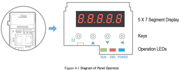
There is a Panel Operator on the front of the Drive, as is shown in Figure 4-1.
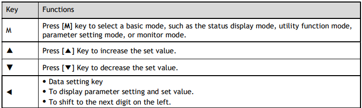
The names and functions of the keys on the Panel Operator are as follows.
4.1.2 Basic Mode Selection
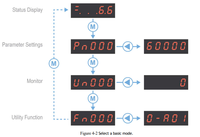
The basic modes include Status Display Mode, Parameter Setting Mode, Utility Function Mode, and Monitor Mode. Select a basic mode with [M] key to display the operation status, set parameters and operation references, as is shown in Figure 4-2.
4.1.3 Status Display Mode
Power ON the Drive and wait for a while, the Panel Operator will initially display the Servo Status.
The information displayed by the status is divided into two parts:
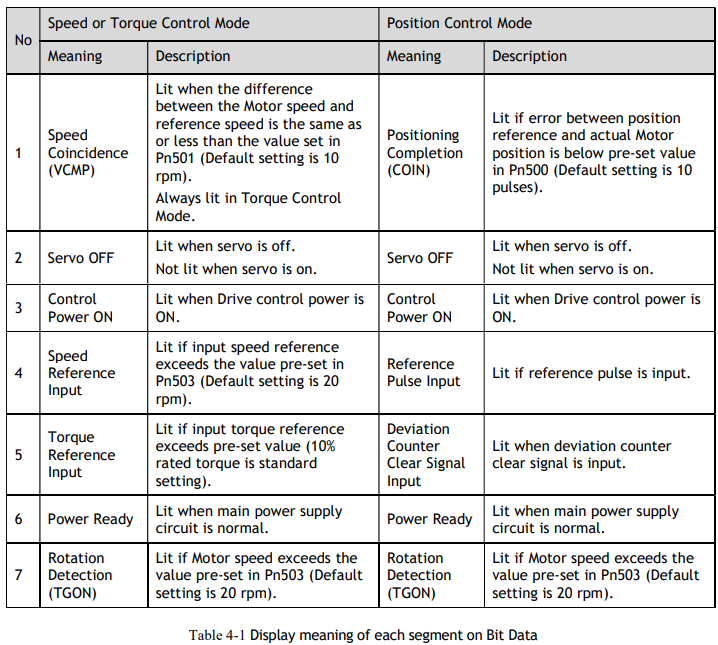
The first two digits are called Bit Data, what indicates the signal states during the operation of Drive.
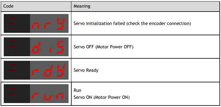
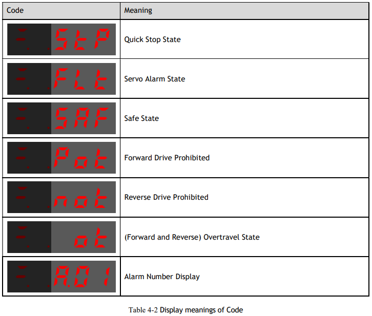
The last three digits are called Code, what indicates the operation states of Drive.
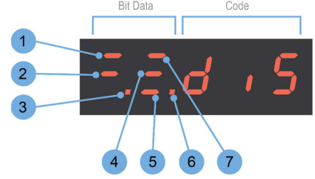
The display meaning of each segment on Bit Data are shown in Table 4-1, and they have different meanings under Speed or Torque Control Mode and Position Control Mode.
The display meanings of Code are shown in Table 4-2

4.1.4 Parameter Setting Mode
Functions can be selected or adjusted by setting parameters. There are two types of parameters.
Function Parameters: the functions allocated to each digit of the Panel Operator can be selected.
Adjustment Parameters: a parameter is set to a value within the specified range of the parameter.
For a description of the parameter settings, please refer to the section Chapter 12 Parameters.
Function Parameters Setting
The example below shows how to change parameter Pn003 (Application Function Selections 3) from 0000 to 1032.
Step 1 Press [M] key several times to select the Parameter Setting Mode.
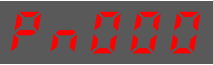
Step 2 Press [▲] key or [▼] key to select the parameter Pn003.
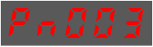
Step 3 Press [◄] key to display the current value of Pn003.
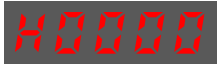
Step 4 Press and hold [◄] key for 1 second or more, and then a flashing decimal point will appear at the bottom right of the 5th digit.

Step 5 Press [▲] key twice, changing the value of the 5th digit from 0 to 2.
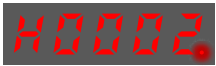
Step 6 Press [◄] key once, moving the flashing decimal point to the 4th digit.
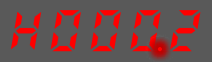
Step 7 Press [▲] key three times, changing the value of the 4th digit from 0 to 3
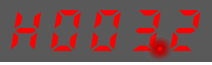
Step 8 Press [◄] key twice, moving the flashing decimal point to the 2nd digit.
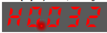
Step 9 Press [▲] key once, changing the value of the 2nd digit from 0 to 1.
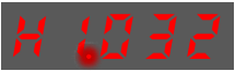
Step 10 Press and hold [◄] key for 1 second or more to return to the display of the Pn003 parameter value or press the [M] key to return to the display of the Pn003.
----End

Adjustment Parameters Setting
The example below shows how to change parameter Pn102 (Speed Loop Gain) from 100 to 85.
Step 1 Press [M] key several times to select the Parameter Setting Mode.
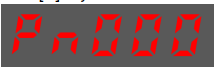
Step 2 Press [▲] key or [▼] key to select the parameter Pn102
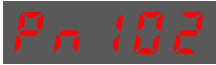
Step 3 Press [◄] key to display the current value of Pn102.
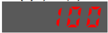
Step 4 Press [▲] key or [▼] key to change the value to 00085.
Press and hold [▲] key or [▼] key to jump the setting value quickly.
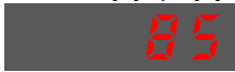
Step 5 Press [◄] key or [M] key to return to the display of Pn102.
----End
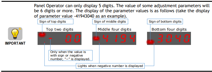
The example below shows how to change parameter Pn504 (Deviation Counter Overflow Alarm) from 41943040 to 42943240.
Step 1 Press [M] key several times to select the Parameter Setting Mode.
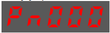
Step 2 Press [▲] key or [▼] key to select the parameter Pn504
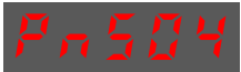
Step 3 Press [◄] key to display bottom four digits of the current value of Pn504.
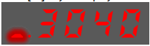
Step 4 Press and hold [◄] key for 1 second or more, and then a flashing decimal point will appear at the bottom right of the 5th digit.
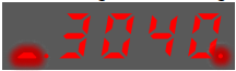
Step 5 Press [◄] key twice, moving the flashing decimal point to the 3rd digit.

Step 6 Press [▲] key twice, changing the value of the 3rd digit from 0 to 2.
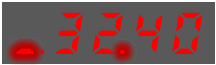
Step 7 Press [◄] key four times, moving the flashing decimal point to the 3rd of middle four digits.
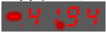
Step 8 Press [▲] key once, changing the value of the 3rd digit from 1 to 2.
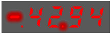
Step 9 Press and hold [◄] key for 1 second or more to return to the display of the Pn504 parameter value or 8press the [M] key to return to the display of the Pn504.
----End
4.1.5 Monitor Mode
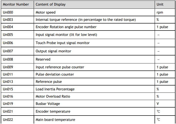
The Monitor Mode can be used for monitoring the reference values, I/O signal status, and Drive internal status.
The Monitor Mode can be selected during Motor operation.
Select Monitor Mode
The example below shows how to display, the contents of monitor number Un003 (when the Motor rotates at 100).
Step 1 Press [M] key several times to select the Monitor Mode.
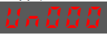
Step 2 Press [▲] key or [▼] key to select the monitor number Un003.
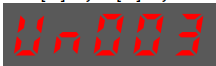
Step 3 Press [◄] key to display the data of Un003.
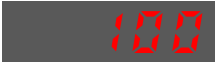
Step 4 Press [◄] key to return to the display of Un003.
----End
Contents of Monitor Mode Display
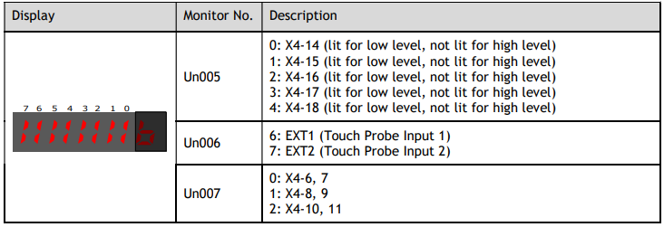
The status (low level or high level) of input signal allocated to each input terminal is displayed.

4.1.6 Utility Function Mode
This section describes how to apply the basic operations using the Panel Operator to run and adjust the Motor.
The following table shows the parameters in the Utility Function Mode.
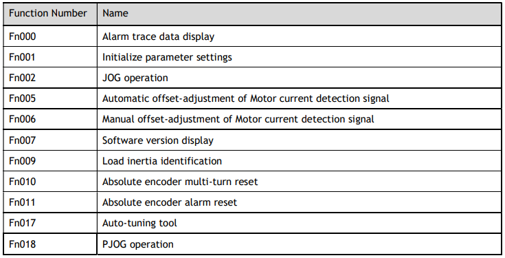
Fn000 (Alarm trace data display)
The alarm trace data display can display up to ten previously occurred alarms. The following are the steps to display the alarm trace data.
Step 1 Press [M] key several times to select the Utility Function Mode.

Step 2 Press [▲] key or [▼] key to select the function number Fn000.
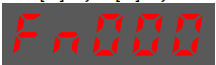
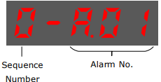
Step 3 Press [◄] key to display latest alarm number.
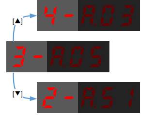
Step 4 Press [▲] key or [▼] key to view the other alarm data.
Step 5 Press the [◄] key to return to the display of the Fn000.
Press and hold [◄] key for 1 second or more to clear all the alarm trace data.
----End
Fn001 (Initialize parameter settings)
The following are the steps to initialize parameter settings.
Step 1 Press [M] key several times to select the Utility Function Mode.
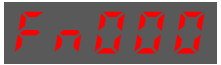
Step 2 Press [▲] key or [▼] key to select the function number Fn001.
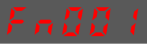
Step 3 Press [◄] key, and Panel Operator displays as below.
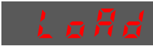
Step 4 Press and hold [◄] key for 1 second to initialize the parameter settings, until Panel Operator displays and blinks done, which indicates the initialization of parameter setting has been completed.

Step 5 Release [◄] key to return to the display of the Fn001.
----End
Fn002 (JOG operation)
This utility function often used for trial operation, refers to the section 9.3.3 JOG Operation.
Fn005 (Automatic offset-adjustment of Motor current detection signal)
Motor current detection offset adjustment has been performed before shipping. The user need not perform this adjustment.

The following are the steps to execute the automatic offset adjustment.
Step 1 Press [M] key several times to select the Utility Function Mode.

Step 2 Press [▲] key or [▼] key to select the function number Fn005.
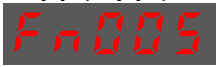
Step 3 Press [◄] key, and Panel Operator displays as below.

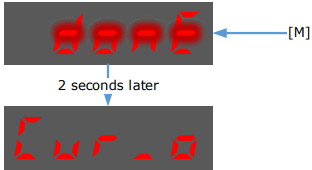
Step 4 Press [M] key to execute the automatic offset adjustment.
Panel Operator displays and blinks done, and 2 seconds later, it will return to previous display.
Step 5 Press the [◄] key to return to the display of the Fn005.
----End
Fn006 (Manual offset-adjustment of Motor current detection signal)
To adjust the offset, perform the automatic adjustment (Fn005) first. And if the torque ripple is still big after the automatic adjustment, perform the manual offset-adjustment as follow.

Step 1 Press [M] key several times to select the Utility Function Mode.
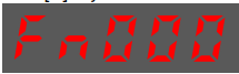
Step 2 Press [▲] key or [▼] key to select the function number Fn006.
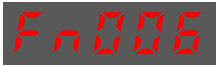
Step 3 Press [◄] key, and Panel Operator displays as below.
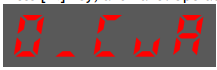
Step 4 Press [M] key for switching the display between 0_CuA (phase-U) and 1_Cub (phase-V).

Step 5 Select one phase display (e.g., 1_Cub, phase-V), and press and hold [◄] key for 1 second or more, Panel Operator will display the current offset value.

Step 6 Press [▲] key or [▼] key to change the offset value.
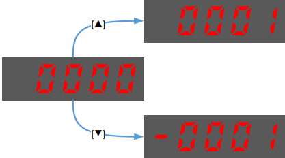
NOTE: the offset can be adjusted from -1024 to 1024.
Step 7 Press and hold [◄] key for 1 second or more to return to the phase display.
Step 8 Press [◄] key to return to the display of the Fn006.
----End
Fn007 (Software version display)
The following are the steps to display the software versions.
Step 1 Press [M] key several times to select the Utility Function Mode.
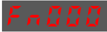
Step 2 Press [▲] key or [▼] key to select the function number Fn007.

Step 3 Press [◄] key to display the software versions.
Step 4 Press [M] key serval time to display between DSP version, FPGA/CPLD version, Voltage class and Structure code.
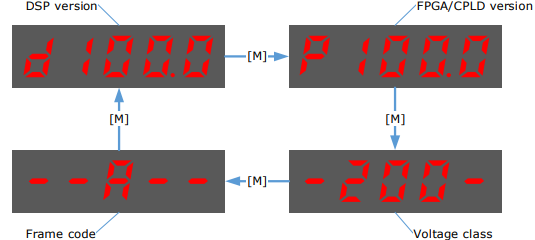
Step 5 Press [◄] key to return to the display of the Fn007.
----End
Fn009 (Load inertia identification)
This utility function often used for tuning, refers to the section 1.
Fn010 (Absolute encoder multi-turn reset)

Step 1 Press [M] key several times to select the Utility Function Mode.
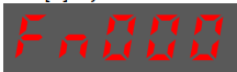
Step 2 Press [▲] key or [▼] key to select the function number Fn010.
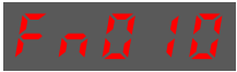
Step 3 Press [◄] key, and Panel Operator displays as below.
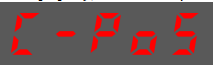
Step 4 Press [M] key to reset the absolute encoder multi-turn data.

Step 5 Press [◄] key to return to the display of the Fn010.
----End
Fn011 (Absolute encoder alarm reset)

Step 1 Press [M] key several times to select the Utility Function Mode.
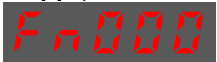
Step 2 Press [▲] key or [▼] key to select the function number Fn011.

Step 3 Press [◄] key, and Panel Operator displays as below.

Step 4 Press [M] key to reset the absolute encoder multi-turn data.

Step 5 Press [◄] key to return to the display of the Fn011.
----End
Fn017 (Auto-tuning tool)
This utility function often uses used for tuning, refers to the section 10.9.2 Auto-Tuning Tool.
Fn018 (PJOG operation)
This utility function often used for trial operation, refers to the section 9.5 Program Jogging.
4.2 Motion Perfect
Motion Perfect is a Microsoft Windows™ based application for the PC, designed to be used in conjunction with Trio Motion Technology's range of multi-tasking motion controllers, servo drives, HMI, and IO expansion products.
A PC with the following specifications is required to run Motion Perfect:
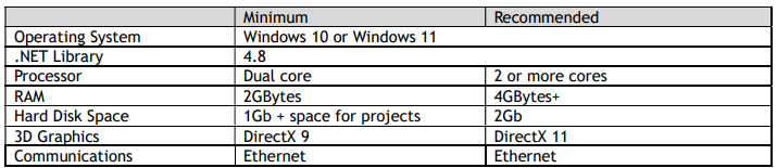
As of 14th January 2020, Microsoft has dropped support for Windows 7. The main consequence of this is that PCs running Windows 7 or older will be more open to malware infection as security related patches will no longer be available. There is no guarantee that all Motion Perfect functionality will work with older operating systems.
Motion Perfect is a free download and is available to from the Trio web site (www.triomotion.com).
4.3 Connection Setup
To communicate with DX3 the drive must be connected to a Trio controller via EtherCAT or and the Trio controller needs to be connected to a PC via Ethernet and the PC needs to be running Motion Perfect. The DX3 can also be connected directly to the PC via USB in Motion Perfect to access the drive commissioning screens.
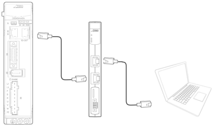
4.3.1 EtherCAT Connection
To make the initial connection to a controller you:
Make sure that your controller is powered up and connected to the computer.
Start Motion Perfect. Once it has started up the initial screen should be displayed.
Select "Connect in Sync mode" from the "Controller" menu. As Motion Perfect has not been connected before the "Connection" dialog will be displayed.
Select the ‘Ethernet’ as the communications interface used by your controller. Then enter the IP address of the controller (default 192.168.0.250) and the TCP port (default 23).
Click on the "Apply & Connect" button. The "Connect" will close and Motion Perfect will go into Sync Mode showing the Controller Tree on the left.
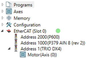
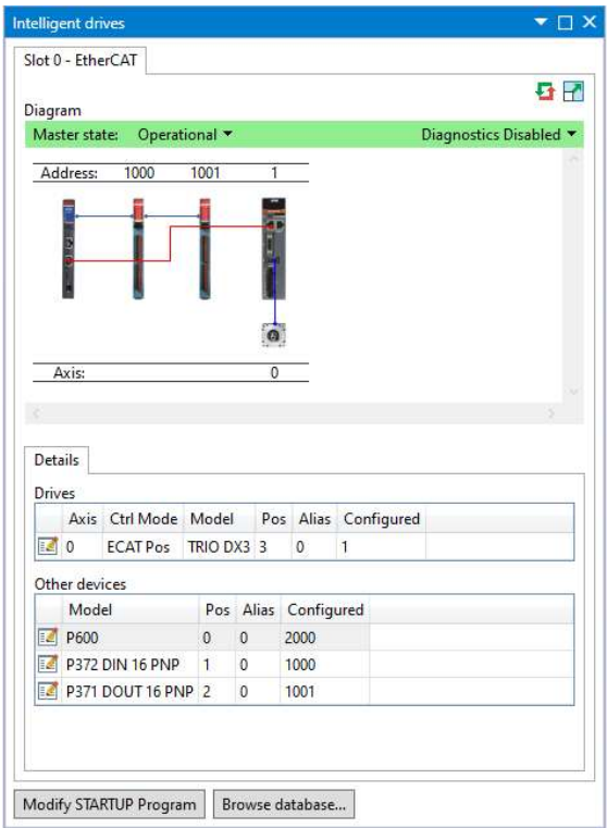
The drive will be automatically detected by the Trio controller and appear as an EtherCAT node. This can be seen in either the controller tree, or the intelligent drives tool.
Controller Tree example
Intelligent Drives tool example.
EtherCAT State
If the EtherCAT state is not operational (green indicator in the controller tree, and green banner in Intelligent Drives), it may be necessary to re-start the EtherCAT network.
A re-start of the EtherCAT network can be issued from either the controller tree by right clicking on the EtherCAT root node, or from the Intelligent Drives tool by right clicking on the controller.
This will force the Controller to re-scan for devices on the EtherCAT network.
Axis Assignment
To operate correctly the controller must assign the drive an axis number. The rules for axis assignment are:
If there is a NODE_AXIS entry in MC_CONFIG for the node number (based on network position) use axis number specified by NODE_AXIS.
If the Drive has a non-zero device node number (Pn704) and this node number is unique on the network, then the axis number will be the node number -1. Node number 13 would be axis number 12.
Otherwise, the axis number is allocated based on the network position and AXIS_OFFSET. If AXIS_OFFSET is 0, the first EtherCAT drive would be axis 0, then second axis 1, etc.
By default, Drives are allocated axis numbers based on network position.
If there is a conflict during the axis allocation process, and the drive cannot be allocated a node number the EtherCAT network will not achieve an operational state.
Typical reasons for this are:
Duplicate axis number allocation in MC_CONFIG. To resolve this, change the NODE_AXIS command in MC_CONFIG to avoid the duplication.
Conflict with local hardware. If the Controller has a local axis hardware, this will use axis 0 (zero), which may cause a conflict with the EtherCAT network. To change the base number of axis allocation of either the local hardware or the EtherCAT network, use the AXIS_OFFSET command in MC_CONFIG. The command AXIS_OFFSET(-1) = 32 will force the local hardware axis allocation to start at axis 32, leaving the lower axis numbers free for EtherCAT.
4.3.2 USB Connection
Alternatively, you can connect directly from the DX3 to your PC by using a USB connection cable to access the commissioning screens.
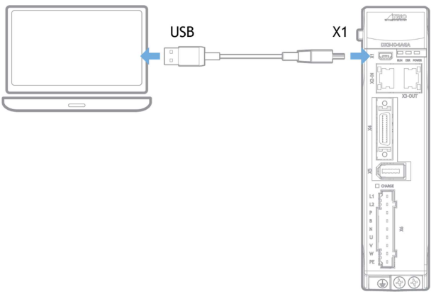
To set up the USB connection, select the external device or network option on the Motion Perfect connection screen. Then select the USB in the connection parameters dropdown menu.
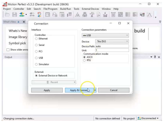
The first time you connect through USB on a computer, Motion Perfect will need to install the necessary drivers through a pop up if it detects they are not yet installed.
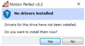
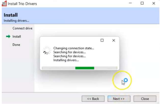
Answer ‘Yes’ to the USB driver installation, then Motion Perfect will install the USB drivers for the device.
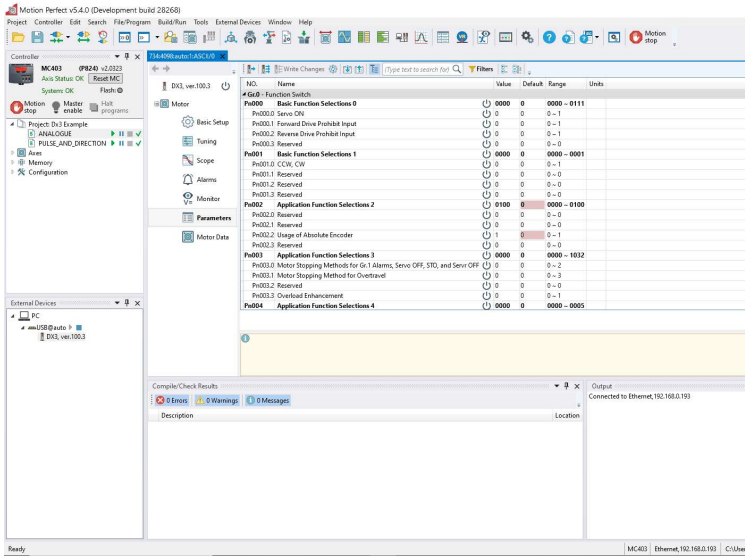
Once the drive is connected the display will appear and the commissioning screen can be used.
4.4 Drive Commissioning Screens
In either case, double clicking on the drive or motor in either the Controller Tree or the Intelligent Drives tool will open the device configuration screen. This is where all drive configuration and commissioning tools can be found.
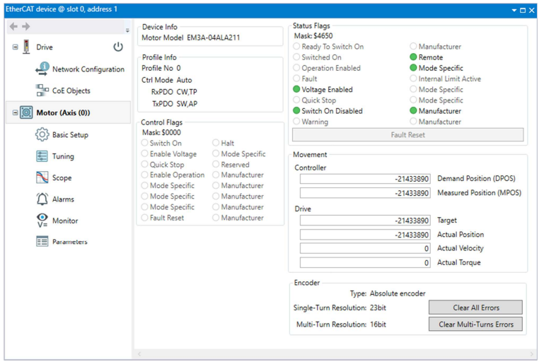
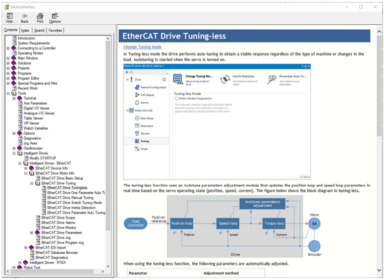
From any of the device configuration screens, for help or more information, pressing F1 will launch the Motion Perfect help based on the screen in view.
The commissioning screens for the Drive are listed below. The menu is split into 2 groups, Drive and Motor. The Drive screens are for status and operations that are not necessarily axis specific. The Motor screens show detail that is axis specific.
Drive
EtherCAT information.
Device information.
Update firmware (DSP and FPGA).
Drive status.
Network Configuration
Flexible process data mapping.
CoE Objects
Read / Write access to all objects.
Create custom object lists.
Display values in decimal or hexadecimal.
Motor
Motor model detected.
Live monitor of key parameters used by controller.
o Control word, Status word.
o DPOS, MPOS.
o Target.
o Actual Position, Actual Velocity, Actual Torque.
o Status of motor feedback device.
Basic Setup
Allows easy access to basic drive configuration.
Parameters that define the physical operation of the drive.
o Power supply type.
o Motor Direction and Abs. Encoder Usage.
o Behaviour in case of alarm.
o Internal torque limit.
o Brake control.
Tuning
Selection of tuning mode.
Access to tuning tools.
Access to control law parameters though graphical interface.
Generate test move without using the command line.
Scope
Select up to 8 drive parameters to capture.
Data capture performed on the drive.
Zoom / Cursors on graph.
Save and Load graph data.
Generate test move without using the command line.
Alarms
View active alarm and historical alarm log
Trouble shooting tips for all alarm codes.
Monitor
Read only access to drive status.
Items in logical groups for viewability.
Show / Hide option to customize view.
Import / Export monitor item set.
Parameters
Read / Write access to all drive parameters.
Folding tree structure for easy navigation.
Text search for easy location based on name.
Filters to identify changes.
Import and export of full or partial parameter set.
Create STARTUP program based on full or partial parameter set.
Motor
View motor details.
4.5 Basic Operation
To ensure safe and correct operation, check the following items before you start.
Make sure that the Drive and Motor are installed, wired, and connected correctly.
Make sure that the correct power supply voltage is supplied to the Drive.
Make sure that there are no loose parts in the Motor mounting.
If you are using a Motor with an Oil Seal, make sure that the oil seal is not damaged. Also make sure that oil has been applied.
If you are performing trial operation on a Motor that has been stored for a long period of time, make sure that all Motor inspection and maintenance procedures have been completed.
If you are using a Motor with a Holding Brake, make sure that the brake is released in advance. To release the brake, you must apply the specified voltage of 24 VDC to the brake.
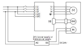
Once connected to a motor, when the Drive is powered up it will auto detect the motor and perform an auto setup which will allow operation of the motor.
The default power supply selection for the main circuit is Three-phase, 200 VAC, 50Hz. If the supply in use is different to this the drive will generate an alarm. The correct supply type can be selected from the Basic Setup page in the drive commissioning screens or by directly writing to parameter Pn007.1 and Pn007.3
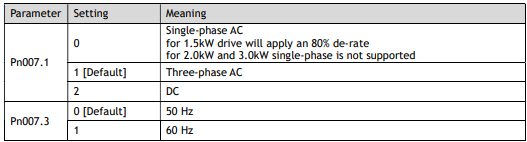
Once the supply type has been changed the drive will require a re-start for the new selection to apply.
If using an absolute encoder, the drive will generate an alarm if it detects a low battery voltage at the encoder. If a battery is fitted and the voltage is correct, this alarm can be cleared from the Motor page in the drive commissioning screens. If there is no battery fitted, then the usage of the encoder will need to be changed to incremental. Changing the encoder usage from absolute to incremental will not change the encoder resolution but will ignore multi-turn information from the encoder and inhibit the low battery voltage alarm. The correct encoder usage can be selected from the Basic Setup page in the drive commissioning screen or by writing directly to parameter Pn002.2.

Once the encoder usage has been changed the drive will require a re-start for the new selection to apply.
To perform simple motion the Move panel in the Scope page (or Tuning page) in the drive commissioning screens can be used. This offers either Jog or Program Jog motion.
4.5.1 Drive Firmware
The version of firmware installed on the DX3 drive may not always be the current recommended type.
The current version can be checked by going online to the drive via Motion Perfect and looking at the Drive section of the DX3’s properties. An example of this is shown below. To initiate the update of firmware to the drive select the Load Firmware button and follow the on-screen instructions when prompted.
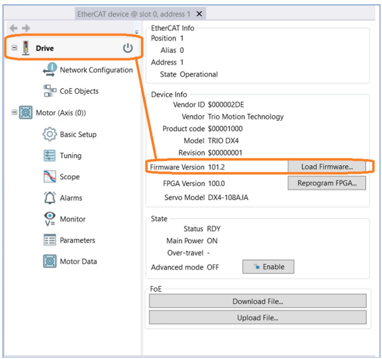
Firmware versions are always available for download from the Trio website on the DX3 Product page -Software section.
The correct firmware to download is based on the frame size of the DX3. Using the information below is also an easy-to-use indication on the file name type to use.
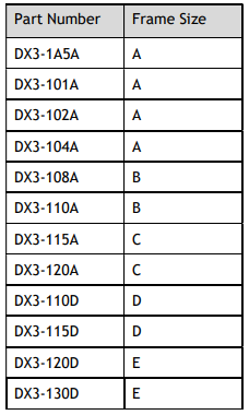
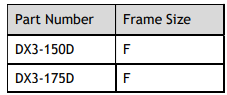
The firmware files have the .bin file extension.
Example:
DX3_DSP_APP_A_E_A000_V101B4.bin A frame size firmware version
DX3_DSP_APP_A_E_B000_V101B4.bin B frame size firmware version
DX3_DSP_APP_A_E_C000_V101B4.bin C frame size firmware version
4.5.2 Holding Brake
A holding brake is used to hold the position of the moving part of the machine when the drive is turned off, so that moving part does not move due to gravity or an external force.
Wiring details for the holding brake can be found in 3.6.4 Holding Brake Wiring.
If the motor has a holding brake a digital output on the drive can be assigned for brake control. Any of the digital outputs on the drive can be configured as the brake control output.
The assignment is made by selecting from the Basic Setup page in the drive commissioning screens or by writing directly to parameter Pn511.

Selecting a digital output in the Basic Setup screen will enable the brake control timing parameters.
Brake Operating Sequence
The time required to release the brake, and the time required to brake should be considered to determine the brake operation timing, as described below.
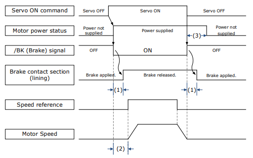
(1): The brake delay times for motors with Holding Brakes.
(2): Before you output a reference from the host controller to the drive, wait for at least 50 ms plus the time required to release the brake after you send the S-ON command.
(3): Use Pn506 (Brake Engage Delay Time), Pn507 (Brake Engage Speed Threshold), and Pn508 (Brake Engage Timeout) to set the timing of brake operation.

Brake Control when Motor is Stationary
Disabled -> Enabled.
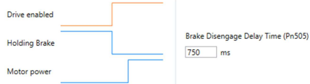
The brake disengage delay time controls the sequence and delay of brake signal when the drive changes from disabled to enabled when the motor is stationary.

If Pn505 is a positive value, when the Servo ON command is received, the brake signal will change first, and then power will be supplied to the motor after the delay time.
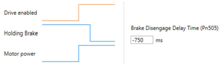
If Pn505 is a negative value, when the Servo ON command is received, the power will be supplied to the motor immediately, then the brake signal will change after the delay time.
Enabled -> Disabled.
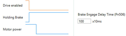
The brake engage delay time controls the delay between the brake signal and motor power when the drive changes from enabled to disabled when the motor is stationary.

When the motor is used to control a vertical axis, the machine moving part may move slightly due to gravity or an external force.
This slight motion can be eliminated by setting the Brake Engage Delay Time (Pn506) so that power supply to the motor is stopped after the brake is applied.

Brake Control when Motor is In Motion
If an alarm occurs or the Servo OFF command is received while the motor is operating, the motor will start stopping and the brake signal will be turned OFF. You can adjust the timing of brake signal output by setting the Brake Engage Timeout (Pn508).

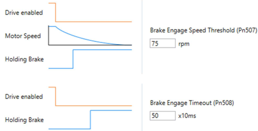
The brake signal changes when either of the following conditions is satisfied:
When the motor speed falls below the level set in Pn507 after the power to the motor is turned OFF.
When the time set in Pn508 is exceeded after the power to the motor is turned OFF.
4.5.3 Jog Motion
The ‘jog’ motion is a velocity profiled move. It has no end point so will generate continuous motion in a specific direction. The velocity profile is defined by acceleration, speed and deceleration value and wil generate a trapezoidal velocity profile. Motion is commanded when the mouse button is clicked and halted when the button is released.
The Jog control is shown below:

The motion profile is controlled three parameters:
Jogging Speed: the maximum speed the jog profile will demand in revs per minute (RPM)
Acceleration Time: the time to accelerate from rest to 1000 RPM in milliseconds (ms)
Deceleration Time: the time to decelerate from 1000 RPM to rest in milliseconds (ms)
To initiate motion, first the drive must be enabled by clicking the ‘Motor enable’ button. This will enable the motion arrows.
Click and hold the arrow buttons to run the motor. The jog motion is continuous; while the button is pressed the motor will run in the direction of the arrow. The motor will stop when the button is released.
The ‘+’ arrow will cause forward rotation, the ‘-‘ arrow will cause reserve rotation.
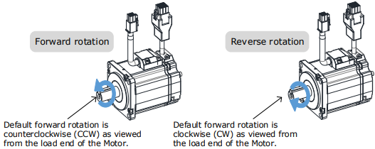
The rotation direction of the Motor can be changed by setting the Motor Direction from the Basic Setup page in the drive commissioning screens. The figure above shows the default setting.
When the drive is enabled via the ‘Jog enable’ button, the drive switches to a local control mode. While in this mode the position change is not sent to the controller. The controller values of MPOS and DPOS will not change during a jog. When the drive is disabled, the update of MPOS and DPOS on the controller resume.
4.5.4 Program Jog Motion
The ‘program jog’ motion is a sequence of two profiled moves of a specific distance with a programmable dwell time between moves. Each move has an independent move distance, acceleration, deceleration, and speed. Both are profiled using a trapezoidal velocity profile. Once started, the motion will repeat until stopped by the user.
The Program Jog control is shown below:
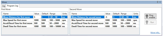
The parameters controlling the program jog are:
Move Distance: the distance to move, this is a signed value where a positive value represents forward motion, and a negative value represents reverse motion. The distance is specified in revolutions (revs)
Max Speed: the maximum speed of the profiled velocity in revs per minute (RPM)
Accel/Decel Time: the time to accelerate from rest to Max Speed in milliseconds (ms). The deceleration value is the same as acceleration.
Dwell Time: the delay time before starting the next move in milliseconds (ms)
To initiate motion, first the drive must be enabled by clicking the ‘PJog enable’ button. This will enable the ‘Run’ button.
Clicking the ‘Run’ button will start the motion.
The sequence will run repeatedly until stopped by either clicking the ‘Run’ button or the ‘PJog enable’ – during motion clicking either will disable the axis.
When the drive is enabled via the ‘PJog enable’ button, the drive switches to a local control mode. While in this mode the position change is not sent to the controller. The controller values of MPOS and DPOS will not change during a jog. When the drive is disabled, the update of MPOS and DPOS will resume.
No comments to display
No comments to display