
6. Application Functions
6.1 Power Supply
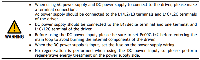
The main circuit and control circuit of the Drive can be operated with an AC power input. When an AC power input is selected, single-phase or three-phase power input can be used. You must set the parameter Pn007.1 and Pn007.3 (use AC power input) according to the applicable power supply.
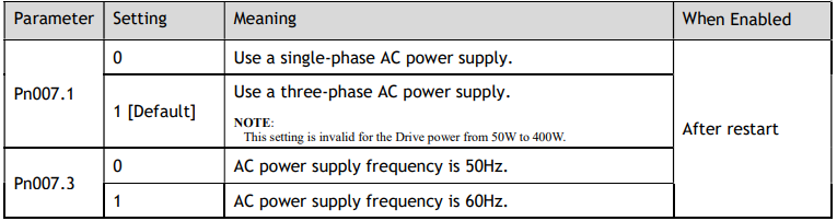
An alarm A.24 (Main Circuit Power Supply Wiring Error) may occur if the setting of Pn007.1 does not match the actual power supply.
6.2 Motor Rotation Direction
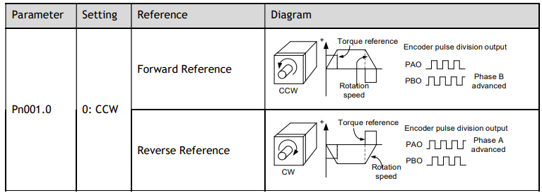
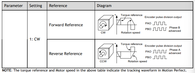
You can reverse the direction of Motor rotation by changing the setting of Pn001.0.
The default setting for Forward Rotation is counter-clockwise (CCW) as viewed from the Drive end.
6.3 Overtravel Limit
6.3.1 Function Description
Overtravel is a safety function of the Drive that forces the Motor to stop in response to a signal input from a limit switch that is activated when a moving part of the machine exceeds the safe range of movement.
The overtravel signals include the P-OT (Forward Drive Prohibit) and the N-OT (Reverse Drive Prohibit) signals.
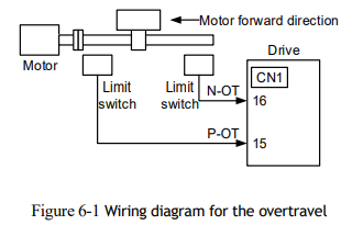
You use the P-OT and N-OT signals to stop the machine by installing limit switches at the positions where you want to stop the machine that is operated by the Motor.
An example of wiring for the P-OT signal and the N-OT signal is shown in Figure 6-1.
Using the overtravel function is not necessary for rotating applications such as rotary tables and conveyors. No wiring for overtravel input signals is required.

6.3.2 Connecting the Overtravel Signal
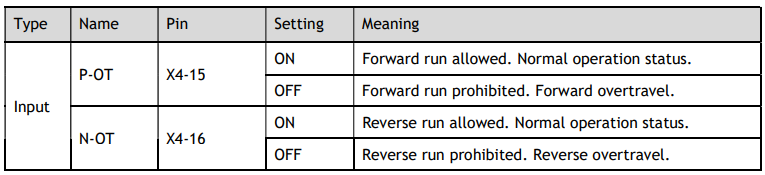
To use the overtravel function, connect the following overtravel limit switch input signal terminals.
6.3.3 Enabling/Disabling the Overtravel Signal
Parameters can be set to disable the overtravel signal. If the parameters are set, there is no need to wire the overtravel input signal.
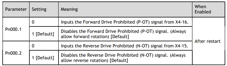
In addition, you can disable the overtravel limit function by not setting the values 1 and 2 to parameter Pn509 (not allocate the P-OT signal and N-OT signal).
6.4 Settings for E-STOP
The E-Stop function refers to the function of forcing the stop of the servo motor by signals from the host device or external device。When using forced stop, the assignment of the forced stop input (E-Stop) signal is required(Pn509=n.XXXX/Pn510=n.□□□X)。There are three types of motor stop modes: DB brake stop, free stop and deceleration stop。

Signal distribution

Note: For more information about THE DISTRIBUTION OF IO signals, see "5.8 IO Signal Assignment".
Force Stop feature selection of stop methods.
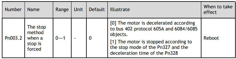
The stop method of the forced stop function is selected by Pn003.2 (the stop method at the time of forced stop).
When setting servo OFF and strong stop
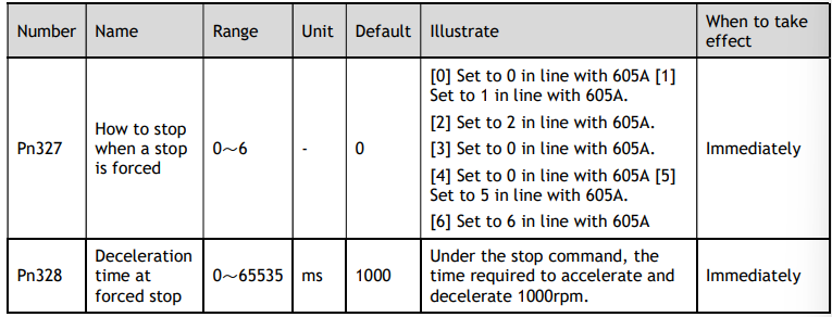
When the servo motor is stopped by setting the deceleration time of the servo motor, the stop mode (Pn327) and the deceleration time (Pn328) at the time of servo OFF and forced stop are set.
The method from forced stop recovery
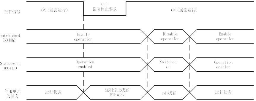
The recovery method for stopping operation by forced stop input (E-STOP) signal is as follows.
If the servo ON command is received when the E-STOP signal IS OFF, the forced stop state is maintained even if the E-STOP signal is set to ON.
Enter the servo OFF command (Disable Operation command), enter the rdy state, please enter the servo ON command (Enable Operation command) again.
6.5 Motor Stopping Methods
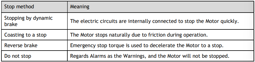
You can use the following methods to stop the Motor when the servo is turned OFF, an alarm (Gr.1 or Gr.2) occurs, in Safe state or overtravel occurs.
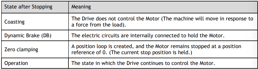
Also, you can let the Motor enter the following states after the Motor stops.
6.5.1 Motor Stop Methods for Gr.1 Alarms, Safety State and Servo OFF
You can select the Motor stopping methods for Gr.1 Alarms occur, in Safe state or Servo OFF by setting the parameter Pn003.0.

6.5.2 Motor Stop Methods for Overtravel
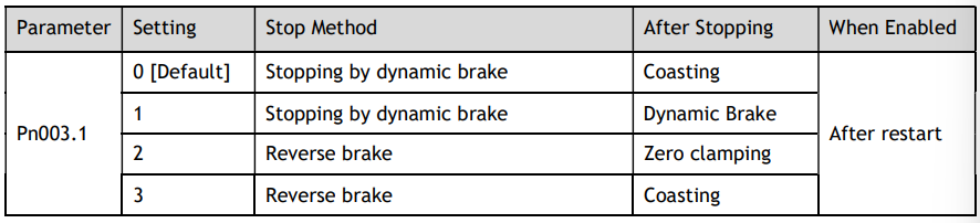
You can select the Motor stopping methods for overtravel occurs by setting the parameter Pn003.1.

6.5.3 Motor Stop Methods for Gr.2 Alarms
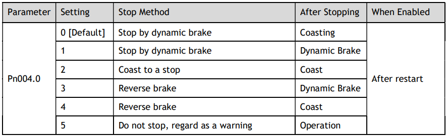
You can select the Motor stopping methods for Gr.2 Alarms occur by setting the parameter Pn004.0.

6.5.4 Reverse Brake Torque Limit Setting
If Pn004.0 is set to 3 or 4, the Motor will be decelerated to a stop using the torque set in Pn405 as the maximum torque.


6.6 Holding Brake
6.6.1 Function Description
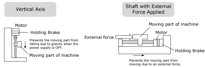
A holding brake is used to hold the position of the moving part of the machine when the Drive is turned OFF, so that moving part does not move due to gravity or an external force.
You can use the brake that is built into a Motor with a Brake, or you can provide one on the machine.
The holding brake is used in the following cases.

6.6.2 Brake Operating Sequence
You must consider the time required to release the brake and the time required to brake to determine the brake operation timing, as described below
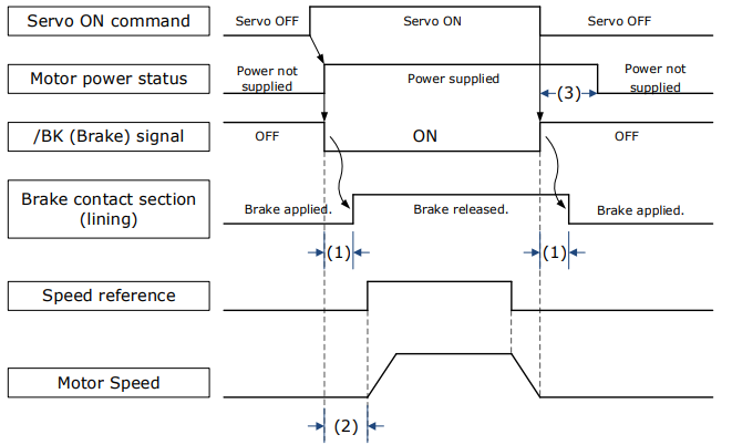
(1): The brake delay times for Motors with Holding Brakes.
(2): Before you output a reference from the host controller to the Drive, wait for at least 50 ms plus the time required to release the brake after you send the S-ON command.
(3): Use Pn506 (Servo OFF Waiting Time), Pn507 (Brake Enable Speed Threshold), and Pn508 (Brake Enable Waiting Time) to set the timing of when the brake will operate and when the servo will be turned OFF.

6.6.3 /BK (Brake) Signal
The /BK signal is turned OFF (to operate the brake) when the Servo is turned OFF or when an alarm is detected. You can adjust the timing of brake operation (i.e., the timing of turning OFF the /BK signal) with the Servo OFF Waiting time (Pn506).

The /BK signal is not allocated in default setting, set its allocation in Pn511.


6.6.4 Output Timing of /BK Signal when Motor is Stopped
When the Motor is stopped, the /BK signal turns OFF as soon as the S-OFF (Servo OFF) command is received. Use the servo OFF delay time (Pn506) to change the timing to turn OFF power supply to the Motor after the S-OFF command is input.
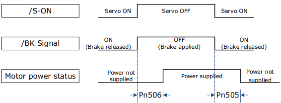


When the Motor is used to control a vertical axis, the machine moving part may move slightly due to gravity or an external force.
You can eliminate this slight motion by setting the servo OFF delay time (Pn506) so that power supply to the Motor is stopped after the brake is applied.

6.6.5 Output Timing of /BK Signal when Motor is operating.
If an alarm occurs or S-OFF command is received while the Motor is operating, the Motor will start stopping and the /BK signal will be turned OFF. You can adjust the timing of /BK signal output by setting the Brake Enable Waiting Time (Pn508).
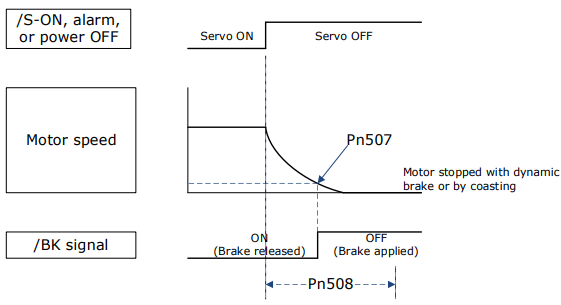
The /BK signal goes to H level (brake ON) when either of the following conditions is satisfied:
When the Motor speed falls below the level set in Pn507 after the power to the Motor is turned OFF.
When the time set in Pn508 is exceeded after the power to the Motor is turned OFF.

6.7 Encoder Setting
6.7.1 Absolute Encoder Selection
Absolute encoders are fitted on motors with an encoder type of L, e.g. MXL-02ALA211. These encoders require a battery supply to retain the absolute encoder data when the Drive power is removed.
With a system that uses an absolute encoder, the host controller can monitor the current position.
Therefore, it is not necessary to perform an origin return operation when the power supply to the system is turned ON.
There are two types of encoders for the Motors. The usage of the encoder is specified in Pn002.2.


6.7.2 Encoder Alarm Resetting
If alarm A.47 or A.48 occurs, replace the battery as soon as possible. After replacing the battery, perform the operation Absolute encoder alarm reset and Fn010 (Absolute encoder multi-turn reset.
For details about replacing the battery, see the section 3.5.3 Battery Case Connection.
6.7.3 Multiturn Limit Setting
The multiturn limit is used in position control for a turntable or other rotating body.
For example, consider a machine that moves the turntable shown in the following diagram in only one direction.
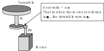
Because the turntable moves in only one direction, the upper limit to the number of revolutions that can be counted by an absolute encoder will eventually be exceeded.
The multiturn limit is used in cases like this to prevent fractions from being produced by the integral ratio of the number motor revolutions and the number of turntable revolutions.
For a machine with a gear ratio of n:m, as shown above, you can set Pn228 (OB 30A9h in EtherCAT) as m, and the value of m - 1 will be the setting for the multiturn limit setting.
The relationship between the number of turntable revolutions and the number of motor revolutions is shown in the following figure.
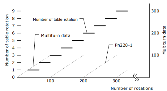


The data will change as shown below when this parameter is set to anything other than the default setting.
If the motor operates in the reverse direction when the multiturn data is 0, the multiturn data will change to the value set in (Pn228-1).
If the motor operates in the forward direction when the multiturn data is at the value set in (Pn228-1), the multiturn data will change to 0.

When you use a single-turn absolute encoder
When you set Pn002.2 = 1 (Use the encoder as an incremental encoder)
6.8 I/O Signal Allocations
Functions are allocated to the pins on the I/O signal connector (X4) in advance. You can change the allocations and the polarity for some of the connector pins. Function allocations and polarity settings are made with parameters.
6.8.1 Input Signal Allocations
Allocation Description
The I/O signal connector (X4) on the Drive provides five pins (points) for allocating the input signals, corresponding to the sub-parameters of Pn509 and Pn510, as is shown in Figure 6-2.
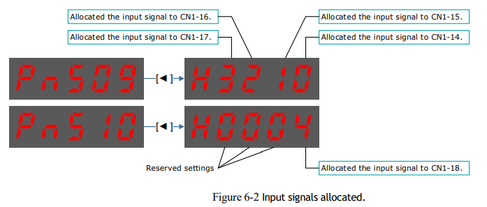
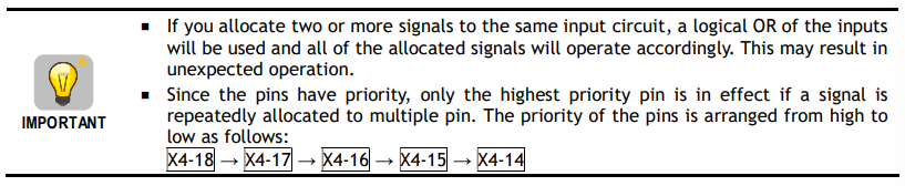
Input Assignment Options
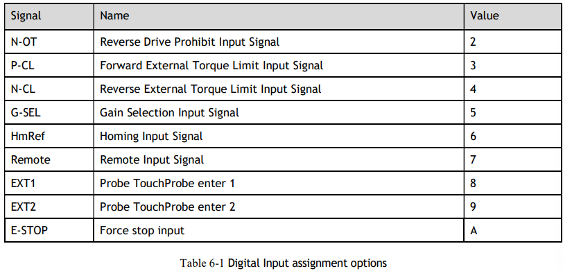
Table 6-1 lists the input signals that can be allocated and their corresponding values. Set the subparameters of Pn509 and Pn510 to use the following values, which means that they are allocated to the corresponding pins.

6.8.2 Output Signal Allocations
Allocation Description
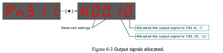
The I/O signal connector (X4) on the Drive provides three group of pins (points) for allocating the output signals, corresponding to the parameter Pn511, as is shown in Figure 6-3.

Default Output Signals
Table 6-2 lists the output signals that can be allocated and their corresponding values. Set the parameter Pn511 to use the following values, which means that they are allocated to the corresponding pins.
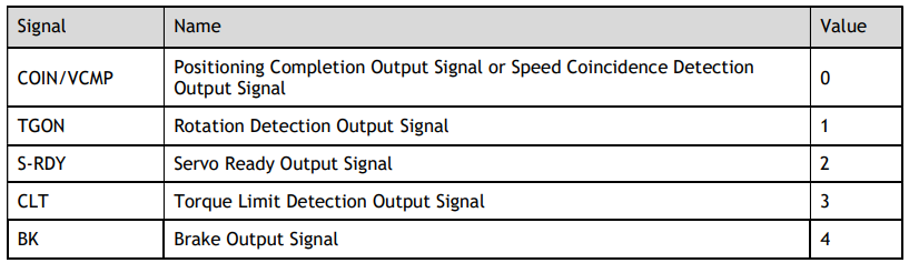
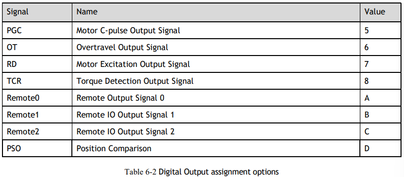
Assignment example
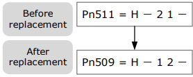
An example of replacing a Servo Ready Output (S-RDY) signal assigned to X4-12, 13 with a Speed Detection Output (TGON) signal assigned to X4-10, 11 is shown below.
6.9 Torque Limit
You can limit the torque that is output by the Motor.
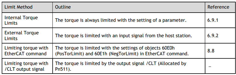
There are four different ways to limit the torque. These are described in the following table.

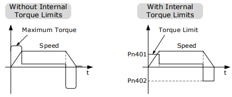
6.9.1 Internal Torque Limits
If you use internal torque limits, the maximum output torque will always be limited to the specified forward torque limit (Pn401) and reverse torque limit (Pn402).

If the setting of Pn401 or Pn402 is too low, the torque may be insufficient for acceleration or deceleration of the Motor.
6.9.2 External Torque Limits
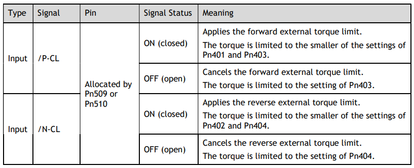
You can limit the torque only when required by the operating conditions of the machine by turning a signal ON and OFF.
You can use this for applications such as stopping on physical contact or holding a workpiece with a robot.
External Torque Limit Reference Signals
The /P-CL (Forward External Torque Limit) and /N-CL (Reverse External Torque Limit) signals are used as the external torque limit reference signals. The /P-CL signal is used for the forward torque limit and the /N-CL signal is used for the reverse torque limit.
Setting the Torque Limits
If the setting of Pn401 (Forward Torque Limit), Pn402 (Reverse Torque Limit), Pn403 (Forward External Torque Limit), or Pn404 (Reverse External Torque Limit) is too low, the torque may be insufficient for acceleration or deceleration of the Motor.


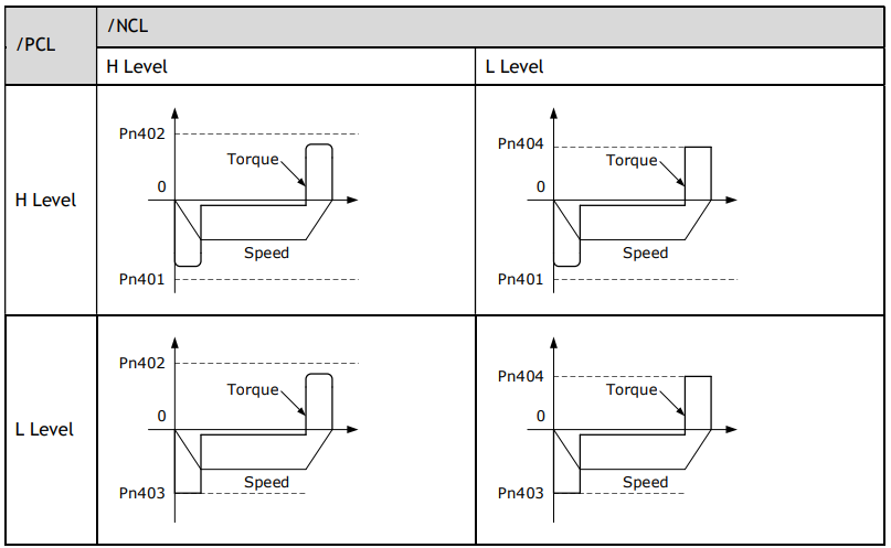
Changes in the Output Torque for External Torque Limits
The following table shows the changes in the output torque when the internal torque limit is set to 300%. In this example, the Motor direction is set to Pn001.0=0 (Use CCW as the forward direction).
Limiting torque with /CLT output signal
This following describes the /CLT signal, which indicates the status of limiting the Motor output torque.

6.10 SEMI F47 Function
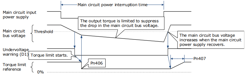
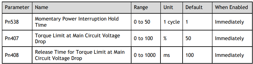
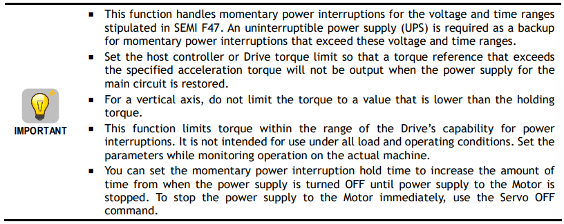
The SEMI F47 function detects an A.D1warning (Undervoltage Warning) and limits the output current if the DC main circuit power supply voltage to the Drive drops to a specified value or lower because the power was momentarily interrupted, or the main circuit power supply voltage was temporarily reduced.
This function complies with the SEMI F47 standards for semiconductor manufacturing equipment.
You can combine this function with the Momentary Power Interruption Hold Time (Pn538) to allow the Motor to continue operating without stopping for an alarm or without recovery work even if the power supply voltage drops.
You can set Pn007.2=1 for slow down the ramp rate of the bus voltage when an undervoltage occurs, allowing the system to run longer. In addition, you can set the Torque Limit at Main Circuit Voltage Drop (Pn407), which is a relative percentage of Pn401 (Forward Internal Torque Limit) or Pn402 (Reverse Internal Torque Limit).
The Drive controls the torque limit for the set time (Pn407) after the Undervoltage warning is cleared.
No comments to display
No comments to display