
9. Trial Operation
9.1 Preparations for Trial Operation
The procedure for trial operation is given below
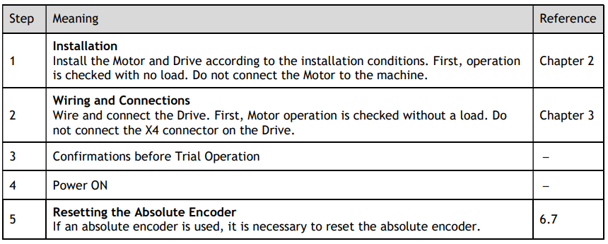
9.2 Inspections and Confirmations
To ensure safe and correct trial operation, check the following items before you start trial operation.
Make sure that the Drive and Motor are installed, wired, and connected correctly.
Make sure that the correct power supply voltage is supplied to the Drive.
Make sure that there are no loose parts in the Motor mounting.
If you are using a Motor with an Oil Seal, make sure that the oil seal is not damaged. Also make sure that oil has been applied.
If you are performing trial operation on a Motor that has been stored for a long period of time, make sure that all Motor inspection and maintenance procedures have been completed.
If you are using a Motor with a Holding Brake, make sure that the brake is released in advance. To release the brake, you must apply the specified voltage of 24 VDC to the brake, for details see the section 3.6.4 Holding Brake Wiring.
9.3 Motor Operation without a Load
You use jogging for trial operation of the Motor without a load.
Jogging is used to check the operation of the Motor without connecting the Drive to the host controller. The Motor is moved at the pre-set jogging speed.

9.3.1 Preparations
Always check the following before you execute jogging.
The main circuit power supply must be ON.
There must be no alarms.
The Servo must not be in Safe State.
The servo must be OFF.
The jogging speed must be set considering the operating range of the machine.
9.3.2 Applicable Tools
Use the Panel Operator of the Drive
Use the Motion Perfect V5.3 or above (Recommended)
9.3.3 JOG Operation
Use the Panel Operator of the Drive
Before performing the JOG operation by using the Panel Operator, you shall check and set the relevant parameters properly.
For the method of checking and setting parameters by using the Panel Operator, refers to the section 4.1.4 Parameter Setting Mode.
Following the below steps to jog the Motor.
Step 1 Press [M] key several times to select the Utility Function Mode.

Step 2 Press [▲] key or [▼] key to select the function number Fn002

Step 3 Press [◄] key, and Panel Operator displays as below.
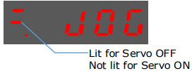
Step 4 Press [M] key to Servo ON (supply power to Motor).
Press [M] key again to Servo OFF (not supply power to Motor).
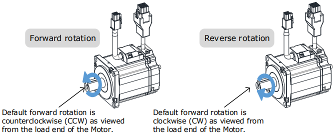
Step 5 Press [▲] key or [▼] key to run the Motor in forward or reverse direction.
Press and hold [▲] key or [▼] key to run the Motor continuously.

Step 6 Press the [◄] key to return to the display of the Fn002.
----End
Use the Motion Perfect
The Motor will operate only while a button is clicked in the Motion Perfect.
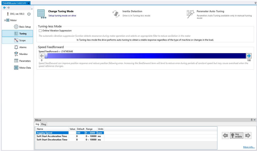
Enter the Tuning page in the drive commissioning section of Motion Perfect, Then select Jog enable to engage the drive and motor. You can then jog the drive by pressing and holding the arrow buttons next to the Jog enable button.
The motor will jog for as long as you hold the arrow buttons. It will more clockwise when using the right button and anticlockwise while using the left.
9.4 Motor Operation with a Load
9.4.1 Precautions


If you will use a holding brake, observe the following precautions during trial operation.
Before you check the operation of the brake, implement measures to prevent vibration from being caused by the machine falling due to gravity or an external force.
First check the Motor operation and brake operation with the Motor uncoupled from the machine. If no problems are found, connect the Motor to the machine and perform trial operation again.
Control the operation of the brake with the /BK (Brake) signal output from the Drive.

9.4.2 Preparations
Always confirm the following before you perform the trial operation procedure for both the machine and Motor.
Make sure that the Drive is connected correctly to both the host controller and the peripheral devices.
Overtravel wiring
Brake wiring
Allocation of the /BK (Brake) signal to a pin on the I/O signal connector (X4)
Emergency stop circuit wiring.
Host controller wiring.
9.4.3 Operation Procedure
Step 1 Enable the overtravel signals.
Refers to the section 6.3 Overtravel Limit.
Step 2 Make the settings for the protective functions, such as the safety function, overtravel, and the brake.
For details on overtravel settings, refers to the section 6.3 Overtravel Limit.
For details on holding brake settings, refers to the section 6.6 Holding Brake.
Step 3 Turn OFF the power supplies to the Drive.
The control power supply and main circuit power supply will turn OFF
Step 4 Couple the Motor to the machine.
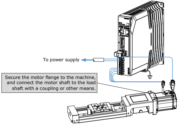
Step 5 Turn ON the power supplies to the machine and host controller and turn ON the control power supply and main circuit power supply to the Drive.
Step 6 Check the protective functions, such overtravel and the brake, to confirm that they operate correctly.
Step 7 If necessary, adjust the servo gain to improve the Motor response characteristics. The Motor and machine may not be broken in completely for the trial operation. Therefore, let the system run for a sufficient amount of time to ensure that it is properly broken in.
Step 8 For future maintenance, save the parameter settings with one of the following methods.
Use Motion Perfect to save the parameters as a file.
Record the settings manually.
This concludes the procedure for trial operation with both the machine and Motor.
----End
9.5 Program Jogging
You can use program jogging to perform continuous operation with a pre-set operation pattern, travel distance, movement speed, acceleration/deceleration time, waiting time, and number of movements.
You can use this operation when you set up the system in the same way as for normal jogging to move the Motor without connecting it to the host controller in order to check Motor operation and execute simple positioning operations.
9.5.1 Preparations
Always check the following before you execute program jogging.
The parameters must not be written prohibited.
The main circuit power supply must be ON.
There must be no alarms.
The Servo must not be in Safe State.
The servo must be OFF.
The range of machine motion and the safe movement speed of your machine must be considered when you set the travel distance and movement speed.
There must be no overtravel.
9.5.2 Operation Description
Program jogging operation consists of two operation patterns (PJOG0 and PJOG1), you can set their relevant parameters, respectively. Figure 9-1 shows an example of position-speed timing diagram in PJOG operation.
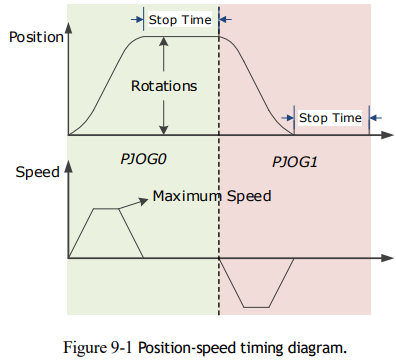
The Drive will operator the Motor repeatedly according to the parameter settings of the two operation patterns until you stop the program jogging operation manually.
You can set the parameters Pn164 and Pn168 to a negative value for reversing the Motor, so that there are four ways of the operation in the program jogging, as is shown in Figure 9-2.
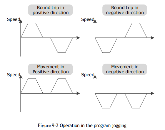
You shall set the Rotations (Pn164 and Pn168) and Max Speed (Pn165 and Pn169) to a proper value. If the Rotations is set too small or the Max Speed is set too large, it is possible that the maximum speed set cannot be reached. In this case, it is necessary to increase the Rotations or decrease the Max Speed.
9.5.3 Relevant Parameters
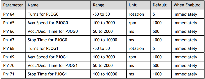
9.5.4 Applicable Tools
Use the Panel Operator of the Drive
Use the Motion Perfect V5.3 or above (Recommended)
9.5.5 Operation Procedure
Use the Panel Operator of the Drive
Before performing the Program Jogging (PJOG) operation by using the Panel Operator, you shall check and set the following parameters properly.

For the method of checking and setting parameters by using the Panel Operator, refers to the section 4.1.4 Parameter Setting Mode.
The following are the steps to run the Motor between the two programmed operation patterns (PJOG0 and PJOG1).
Step 1 Press [M] key several times to select the Utility Function Mode.

Step 2 Press [▲] key or [▼] key to select the function number Fn018.

Step 3 Press [◄] key, and Panel Operator displays as below.

Step 4 Press [M] key to execute this operation, and Panel Operator displays as below

Step 5 Press [◄] key to return to the display of the Fn018.
----End
No comments to display
No comments to display