
11. CONTROL LOOPS
This chapter shows how to program and tune the control loops. Perform the basic steps outlined below. Details follow in the chapter.
For each control loop:
1 or
or  or
or Click the appropriate button to open the loop control screen.
2  Change/verify settings as needed.
3  Click Close to close screen and save changes to amplifier RAM.
4  Click to open the Scope tool.
5  Run a function or profile and adjust settings to tune the loop.
For an overview of control loop theory, see Servo Operating Modes and Control Loops.
11.1: Current Loop Setup and Tuning
Initial current loop proportional gain (Cp) and current loop integral gain (Ci) values can be calculated with The Calculate Function.
Enter basic Current Loop settings
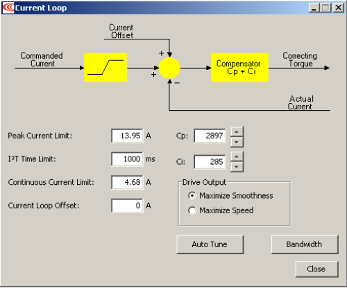
1  Click I Loop to open the Current Loop screen:
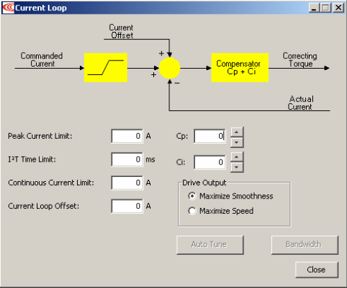
2 Change/verify Current Loop parameters as needed
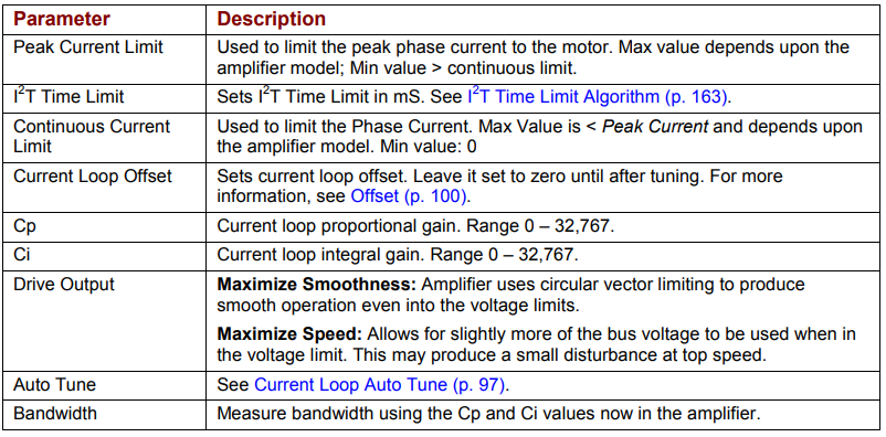
3 Click Close to close screen and save changes to amplifier RAM
Manually tune the Current Loop
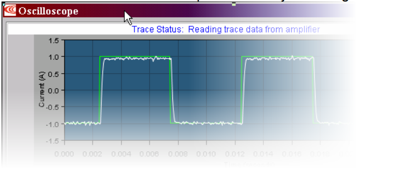
METHOD: Apply square-wave excitation to the current loop and adjust current loop proportional gain (Cp) and current loop integral gain (Ci) to obtain a desired waveform.
For instance:
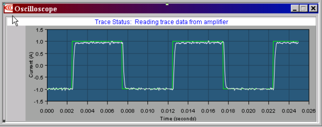
NOTES:
1) During tuning, observe any warnings that appear to the left of the trace.
2) Some users prefer the Auto Tune feature. See Current Loop Auto Tune
1  Click the Scope Tool.
2  Choose Current from theFunction Generator Apply To: list.
3  On the Settings tab, make sure Auto Setup is selected. Auto Setup automatically sets the following parameters:
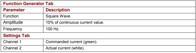
5  Click Start.
6 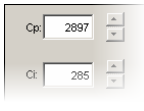 On the Gains tab, adjust current loop proportional gain (Cp):
Set current loop integral gain (Ci) to zero.
Raise or lower Cp to obtain desired step response. (Typically, little or no overshoot with a 100 Hz, low-current square wave.) If the Cp value is too large, ringing may occur. If the Cp value is too low, bandwidth decreases.
7 Adjust current loop integral gain (Ci) until desired settling time is obtained.
8  Press Stop to stop the function generator.
9 On the Main screen, click Save to Flash to avoid losing the changes.
11.2: Current Loop Auto Tune
Tune the Current Loop with Auto Tune
METHOD: The current loop Auto Tune algorithm applies a square-wave command to the current loop and adjusts current loop proportional gain (Cp) and current loop integral gain (Ci) until a desirable waveform is obtained. Initial current loop proportional gain (Cp) and current loop integral gain (Ci) values can be calculated with The Calculate Function.
1  Click I Loop to open the Current Loop screen:
2 Verify that the amplifier is hardware enabled.
3  Click Auto Tune to open screen and start the Current Loop Auto Tune.
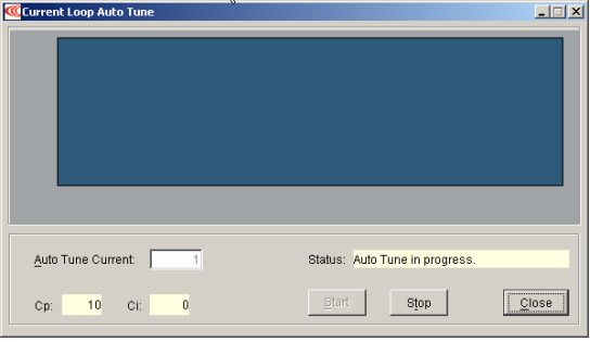
4 To Change the Auto Tune Current, Press Stop, enter the new current in the Auto Tune Current field, and then press Start.
5 Observe the Auto Tune process and results. A typical example:
Sets Cp and Ci to zero and then adjusts Cp and Ci for optimal values.
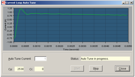
Uses a frequency sweep to determine the small signal, current loop bandwidth.
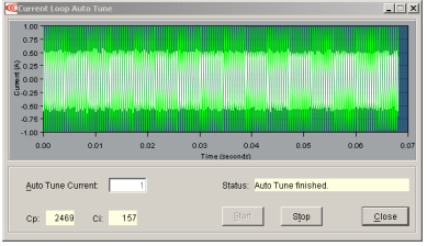
Displays the results: a set of Cp and Ci alternatives, and the bandwidth measured using the high Cp and Ci values.
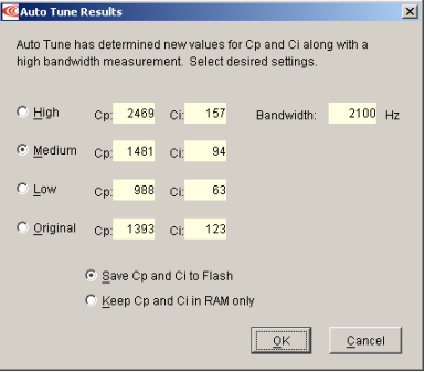
6 Choose an action based on Auto Tune results.
Choose which set of values to save: High, Medium, Low, or Original. The Medium values, selected by default, are appropriate for most applications.
Optionally choose how to save: Save Cp and Ci to Flash or Keep Cp and Ci in amplifier RAM only.
7 Click OK to save the values as chosen, and close the Auto Tune Results window.
11.3: Notes on the Current Mode and Current Loop
11.3.1: Current Loop Diagram
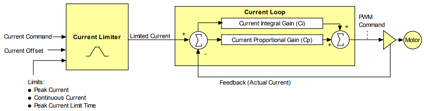
As shown below, the “front end” of the current loop is a limiting stage. The limiting stage accepts a current command, applies limits, and passes a limited current command to the summing junction. The summing junction takes the commanded current, subtracts the actual current (represented by the feedback signal), and produces an error signal. This error signal is then processed using the integral and proportional gains to produce a command. This command is then applied to the amplifier’s power stage.
11.3.2: Current Loop Inputs
• The amplifier’s analog or PWM inputs.
• A CANopen network via the amplifier’s CAN interface.
• A Copley Virtual Motion (CVM) control program.
• The amplifier’s internal function generator.
In velocity or position modes, the current command is generated by the velocity loop
11.3.3: Offset
The current loop offset is intended for use in applications where there is a constant force applied to, or required of, the servomotor and the system must control this force. Typical applications would be a vertical axis holding against gravity, or web tensioning. This offset value is summed with the current command before the limiting stage.
11.3.4: Limits
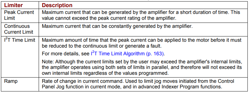
The current command is limited based on the following parameters:
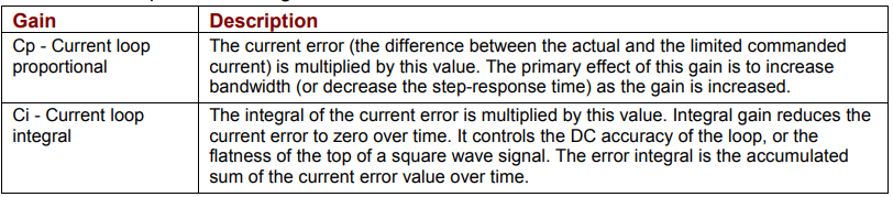
11.3.5: Current Loop Gains
The current loop uses these gains:
11.3.6: Current Loop Output
The output of the current loop is a command that sets the duty cycle of the PWM output stage of the amplifier.
11.4: Velocity Loop Setup and Tuning
Initial velocity loop proportional gain (Vp) and velocity loop integral gain (Vi) values can be calculated with The Calculate Function (p. 46).
Enter basic Velocity Loop settings
1  Click V Loop (screen contents vary with model and configuration):
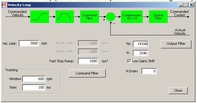
2 Change/verify Velocity Loop parameters as needed.
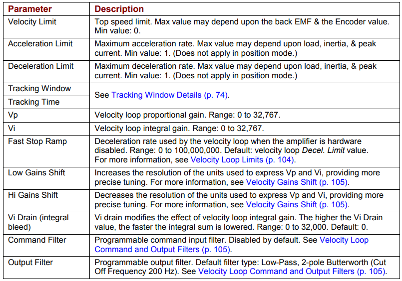
3 Click Close to close screen.
Manually Tune the Velocity Loop
METHOD: Apply square-wave excitation to velocity loop and adjust proportional gain (Vp) and integral gain (Vi) to obtain desired waveform. For instance:
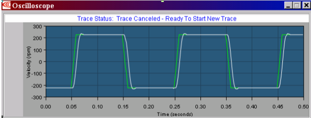
NOTE: During tuning, observe any warnings that appear to the left of the trace
1 Click the Scope Tool.
2  Choose Velocity from the Function Generator Apply To: list.
3  On the Settings tab, make sure Auto Setup is selected. Auto Setup automatically sets the following parameters:
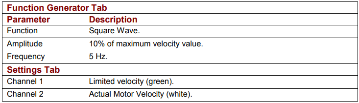
4  Verify that Amplitude value is not excessive for the motor.
5  Click Start.
6 On the Gains tab, adjust velocity loop proportional gain (Vp):
Set velocity loop integral gain (Vi) to zero.
Raise or lower proportional gain (Vp) to obtain desired step response. (Typically, little or no overshoot on a 5 Hz small, slow-speed square wave.)
7 Adjust velocity loop integral gain (Vi) until desired settling time is obtained.
8  Press Stop to stop the function generator.
9  On the Main screen, click Save to Flash to avoid losing the changes
11.5: Notes on the Velocity Mode and Velocity Loop
11.5.1: Velocity Loop Diagram
As shown below, the velocity loop limiting stage accepts a velocity command, applies limits, and passes a limited velocity command to the input filter. The filter then passes a velocity command to the summing junction. The summing junction subtracts the actual velocity, represented by the feedback signal, and produces an error signal. (The velocity loop feedback signal is always from the motor feedback device even when an additional encoder is attached to the load.) The error signal is then processed using the integral and proportional gains to produce a current command. Programmable digital filters are provided on both the input and output command signals.
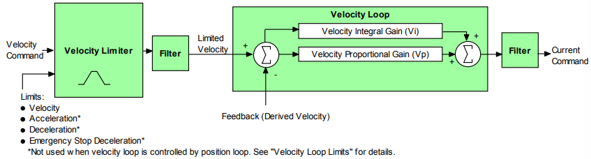
11.5.2: Inputs
In velocity mode, the velocity command comes from one of the following:
• The amplifier’s analog or PWM inputs.
• A CANopen network via the amplifier’s CAN interface.
• A Copley Virtual Motion (CVM) control program.
• The amplifier’s internal function generator.
In position mode, the velocity command is generated by the position loop.
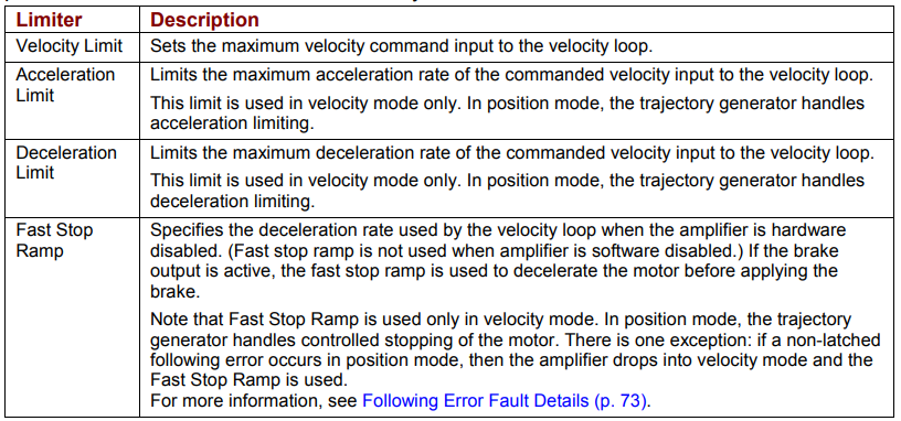
11.5.3: Velocity Loop Limits
The velocity command is limited based on the following set of parameters designed to protect the motor and/or the mechanical system.
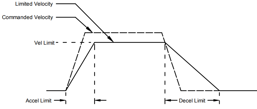
11.5.4: Diagram: Effects of Limits on Velocity Command
The following diagram illustrates the effects of the velocity loop limits.
11.5.5: Velocity Loop Gains
The velocity loop uses these gains:
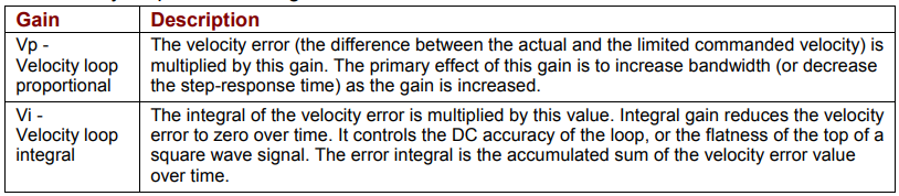
11.5.6: Velocity Gains Shift
The Velocity Gains Shift feature adjusts the resolution of the units used to express Vp and Vi, providing more precise tuning. If the non-scaled value of Vp or Vi is 64 or less, the Low Gains Shift option is available to increase the gains adjustment resolution. (Such low values are likely to be called for when tuning a linear motor with an encoder resolution finer than a micrometer.) If the non-scaled value of Vp or Vi is 24001 or higher, the High Gains Shift option is available to decrease the gains adjustment resolution.
11.5.7: Velocity Loop Command and Output Filters
The velocity loop contains two programmable digital filters. The input filter should be used to reduce the effects of a noisy velocity command signal. The output filter can be used to reduce the excitation of any resonance in the motion system. Two filter classes can be programmed: the Low-Pass and the Custom Bi-Quadratic. The Low-Pass filter class includes the Single-Pole and the Two-Pole Butterworth filter types. The Custom Bi-Quadratic filter allows advanced users to define their own filters incorporating two poles and two zeros.
For more information, see Low-Pass and Bi-Quad Filters.
11.5.8: Velocity Loop Outputs
The output of the velocity loop is a current command used as the input to the current loop.
11.6: Position Loop Setup and Tuning
Initial position loop proportional gain (Pp), velocity feed forward (Vff), and acceleration feed forward (Aff) values can be calculated with The Calculate Function
Enter basic Position Loop settings
1  Click P Loop to open the Position Loop Values screen:
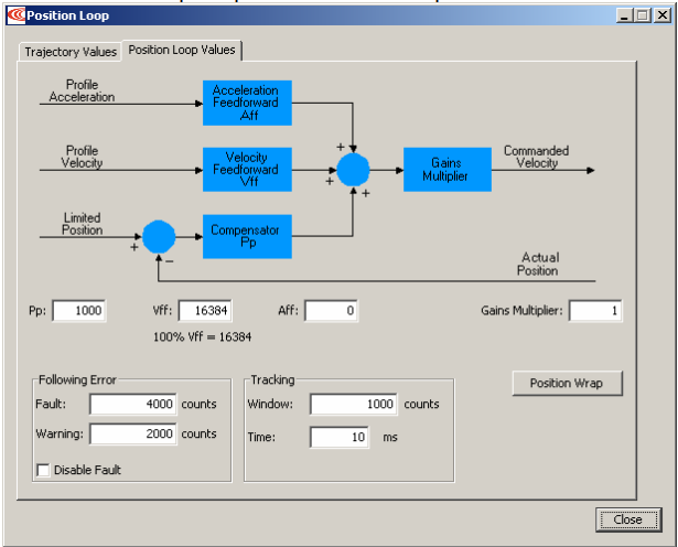
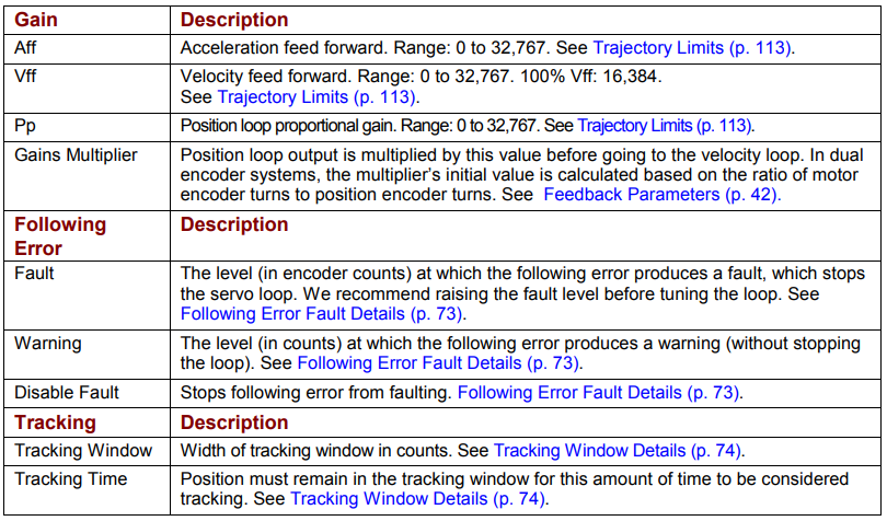
2 Change/verify Position Loop Values as needed. Click Close when done.
3 Optionally click Position Wrap to open the Position Wrap screen:
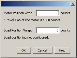
4 Change/verify the position wrap parameters as needed. Set both values to zero to disable position wrapping. Note that the changes do not take effect until OK is pressed. For more information about this feature, see Position Wrap

5 Click on the Trajectory Values tab:
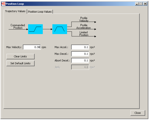
6 Change/verify the trajectory values as needed:
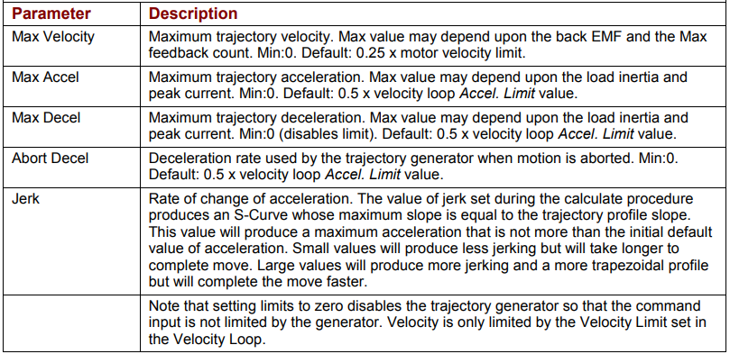
Manually tune the position loop
METHOD: Minimize following error and oscillation by running profiles and adjusting position proportional gain (Pp), velocity feed forward (Vff), acceleration feed forward (Aff) and other settings. For instance:
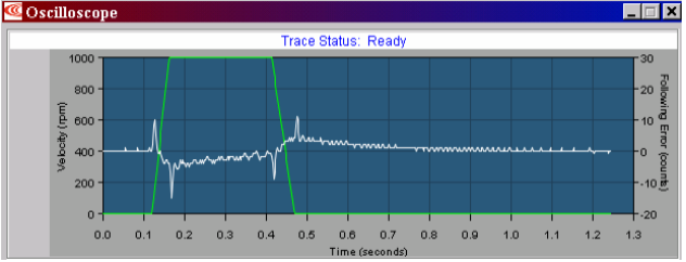
NOTE: During tuning, observe warnings that appear to the left of the trace
1  Click the Scope Tool.
2 Select the Profile tab.
3  On the Settings tab, make sure Auto Setup is selected. Auto Setup
automatically sets the following parameters:
4 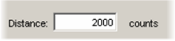 If the Auto Setup default profile distance is not
appropriate, enter an appropriate short distance.
5  Click Start. The Profile Generator executes a short move.
NOTES:
1) The profile may not reach constant velocity during a short move.
2) If a following error occurs, open the Control Panel and click Clear Faults.
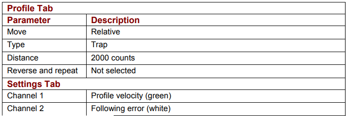
6
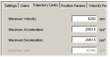 and
and 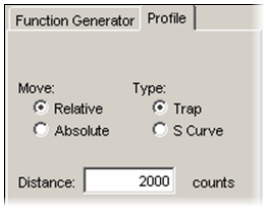
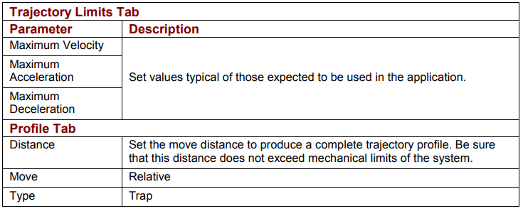
Set up a trapezoidal profile by setting the trajectory limits and distance. See table:
7
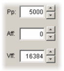
Adjust position proportional gain (Pp) to minimize following error:
On the Gains tab, set velocity feed forward (Vff) and acceleration feed forward (Aff) to zero.
On the Profile tab, click Start. On the Gains tab, adjust position loop proportional gain (Pp) until best result is obtained.
Click Start after each adjustment to test on a new profile move.
NOTES:
1) Too much position loop proportional gain (Pp) might cause oscillation.
2) If a following error occurs, open the Control Panel and click Clear Faults.
8 Adjust velocity feed forward (Vff):
Velocity feed forward (Vff) reduces following error in the constant velocity portion of the profile. Often, a velocity feed forward (Vff) value of 16384 (100%) provides best results.
Click in the Vff field and adjust the value.
Click Start after each adjustment to test on a new profile move.
9 Adjust acceleration feed forward (Aff):
Acceleration feed forward (Aff) reduces following error during profile acceleration and deceleration.
Click in the Aff field and adjust the value.
Click Start after each adjustment to test on a new profile move.
NOTES:
1) If, after tuning the position loop, the motor makes a low frequency audible noise while enabled but not moving, the velocity loop gains (Vp and Vi) may be lowered to reduce the noise. If the gain values are set too low, the response to instantaneous rates of change might be reduced (i.e., slow correction to disturbances or transients).
2) If the amplifier is set up to run in position mode under analog input command, and the analog command signal produces too much noise at the motor after tuning, the Analog Command Filter or the Velocity Loop Command Filter may be used to reduce the noise further.
See Low-Pass and Bi-Quad Filters
10 Tune to multiple sets of profiles representing typical moves that might be executed in the application. Starting with Step 6, repeat the process as needed.
Test S-Curve Profile
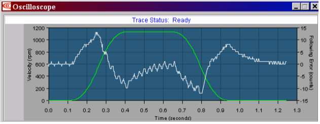
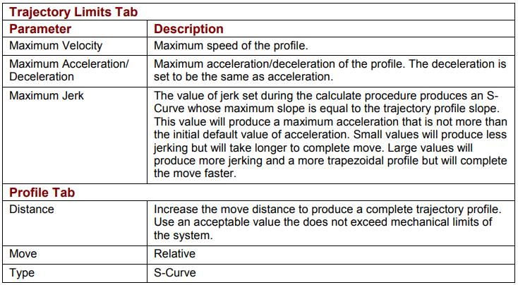
DISCUSSION: If the amplifier will perform S-Curve profile moves, use this procedure to tune the level of jerk. (Jerk is the rate of change of acceleration. S-Curve moves reduce jerk to provide a smooth profile.) Run an S-Curve profile and adjust velocity, acceleration, deceleration, and jerk levels until the desired profile is obtained. For instance:
1
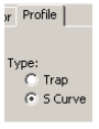
On the Profile tab, click the S-Curve button.
2 Set up an S Curve profile by adjusting the following parameters to represent a typical move under normal operation.
3 Click Start.
4 Try multiple sets of profiles representing typical moves that might be executed in the application. Starting with Set up an S Curve profile, repeat the process as needed.
11.7: Notes on the Position Mode and Position Loop
11.7.1: Position Loop Diagram
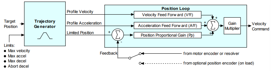
The amplifier receives position commands from the digital or analog command inputs, over the CAN interface or serial bus, or from the CVM Control Program. When using digital or analog inputs, the amplifier's internal trajectory generator calculates a trapezoidal motion profile based on trajectory limit parameters. When using the CAN bus, serial bus, or CVM Control Program, a trapezoidal or S-curve profile can be programmed. The trajectory generator updates the calculated profile in real time as position commands are received.
The output of the generator is an instantaneous position command (limited position). In addition, values for the instantaneous profile velocity and acceleration are generated. These signals, along with the actual position feedback, are processed by the position loop to generate a velocity command.
To bypass the trajectory generator while in digital or analog position modes, set the maximum acceleration to zero. The only limits in effect will now be the velocity loop velocity limit and the current limits. (Note that leaving the maximum acceleration set to zero will prevent other position modes from operating correctly.)
The following diagram summarizes the position loop.
11.7.2: Trajectory Limits
In position mode, the trajectory generator applies these limits to generate the profile.

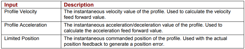
11.7.3: Position Loop Inputs From the Trajectory Generator
The position loop receives the following inputs from the trajectory generator
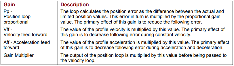
11.7.4: Position Loop Gains
The following gains are used by the position loop to calculate the velocity command:
11.7.5: Position Loop Feedback
Some Copley Controls amplifiers feature dual-sensor position loop feedback, configured as follows:
• Single sensor. Position loop feedback comes from the encoder or resolver on the motor.
• Dual sensor. Position loop feedback comes from the encoder attached to the load. (Note that in either case, velocity loop feedback comes from the motor encoder or resolver.) For more information, see Feedback Notes (p 44).
Position Loop Output
The output of the position loop is a velocity command used as the input to the velocity loop.
11.7.6: Position Wrap
The position wrap feature causes the position reported by the amplifier to “wrap” back to zero at a user-defined value instead of continually increasing. Once set, the reported position will be between 0 and n-1 where n is the user entered wrap value. This feature is most useful for rotary loads that continually turn in one direction and only the position within a revolution is of interest to the user.
Relative moves with the wrap value set will move the relative distance called for. Example; if the wrap value is set to 1000 and a relative move of 2500 is commanded, the axis will turn 2 ½ revolutions.
Absolute moves will move the shortest distance to arrive at the programmed position. This could be in the positive or negative direction. Moves programmed to a point greater then the wrap value will cause an error.
To configure the position wrap feature, see Enter basic Position Loop settings
11.8: Auto Tune all Loops for Linear Motors
The Auto Tune all loops feature is available for use with linear motors.
Make sure motor is mounted firmly and verify accuracy and completeness of
motor data.

Failure to heed this warning can cause equipment damage, injury, or death.
Tune All Loops with Auto Tune (Linear Motors)
At any point, use Back to return to the previous screen. Use Skip to tune the velocity loop without tuning the current loop, or to tune the position loop without tuning the velocity loop.
1 Verify the motor is mounted firmly. Also verify the accuracy and completeness of the motor settings. See Motor/Feedback
Current Loop
2 Make sure the amplifier’s Basic Setup and Motor Phasing procedures have been performed, and that the system is capable of a 10 mm move.
3  Click Auto Tune to open the Current Loop Tune screen.
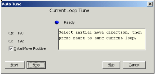
The status indicator is blue when the amplifier is ready for tuning.
4 Verify the Initial Move Positive setting. In most cases, this option should be set. If positive initial motion is not possible, you can specify negative initial motion by clearing this option. For instance, negative initial motion may be used when a vertical axis is at the bottom of the motion range and the positive direction is down.
5 Click Start to tune the current loop. During tuning, the status indicator is amber. Cp and Ci values change as the text in the status box gives progress updates. When the current loop has been tuned, the status indicator turns green, and the status box contains instructions for the next step.
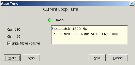
Velocity Loop:
6 Click Next to open the Jog screen.
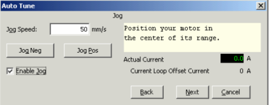
7 Move the motor to the center of its motion range. To use a jog move:
Set the Enable Jog option.
Optionally adjust the jog speed
Jog the motor in either direction to move it to the center of its motion range
8 When the motor is centered, click Next. If the amplifier must apply current to hold the new position against a force (such as gravity in a vertical application), the following message appears:
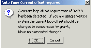
If this message appears, click OK. The Velocity Loop Tune screen opens
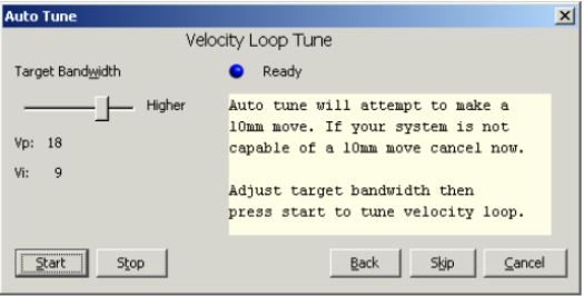
9 Optionally adjust the Target Bandwidth.
TIP: Increase bandwidth for more stiffness in the holding position. Decrease bandwidth to eliminate buzzing or oscillations caused when the load is removed.
10 Click Start to tune the velocity loop. During tuning, the status indicator is amber. Vp and Vi values change as the text in the status box gives progress updates. When the velocity loop has been tuned, the status indicator turns green, and the status box contains instructions for the next step:
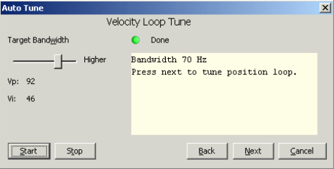
Position Loop:
11 Click Next to open the Position Loop Tune screen:
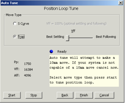
12 Verify the Move Type setting (S-Curve or Trap).
13 For a trapezoidal profile, optionally optimize the tuning along the scale between Best Settling (for quicker settling) and Best Following (for less following error).
14 Click Start to tune the position loop. During tuning, the status indicator is amber. Pp, Vff, and Aff values change as the text in the status box gives progress updates. When the position loop has been tuned, the status indicator turns green, and the status box contains instructions for the next step:
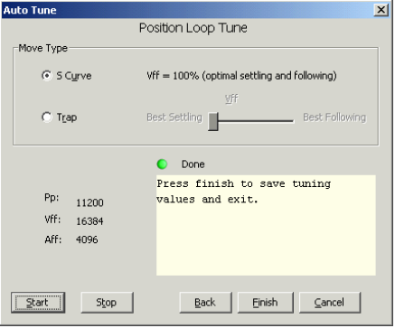
15 Click Finish. See the reminder:
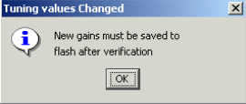
16 Click OK.
17  On the CME 2 Main screen, click Save to Flash
No comments to display
No comments to display