
APPENDIX G: MASKING
G.1: Masking
G.1.1: Selecting Bits in a Register
A register mask describes a selection of bits in a register. Copley Motion Objects uses masks to:
1 Configure methods to monitor the states of selected register bits.
2 Directly read or write the states of register bits.
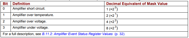
A register mask describes a set of bits. The mask is typically represented by a binary number. For convenience, the register descriptions in this manual provide the decimal mask values for each bit. The decimal equivalent can be calculated as 2 n, where n = the bit number For instance, here is a partial description of the amplifier’s event status register:
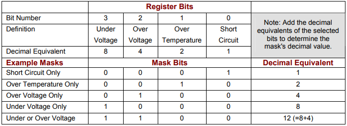
A mask is defined by setting (to value 1) the mask bits that correspond to selected register bits. A simple way to do this is add the decimal equivalents of the mask values of the selected bits. Here are three sample masks for the event status register:
Continue to G.1.2: Mask Usage Examples.
G.1.2: Mask Usage Examples
For instance, the method WriteOutputConfigExt (p. 37) can configure an output to track one or more bits in the amplifier’s event status word.
Example 1: Configure OUT1 to Track Short Circuit Conditions
The general format of WriteOutputConfigExt is:
WriteOutputConfigExt(pin As Integer, config As CML_OUTPUT_PIN_CONFIG, param1 As Integer, Param2 As Integer)
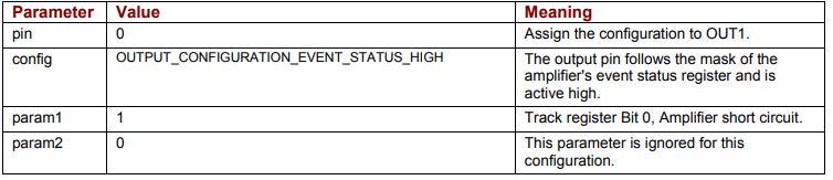
To configure OUT1 to track short circuit conditions, call the method as follows:
WriteOutputConfig 0, OUTPUT_CONFIGURATION_EVENT_STATUS_HIGH, 1, 0
The parameter values are described below.
Example 2: Configure OUT4 to Track Over Temperature and Over Voltage Conditions
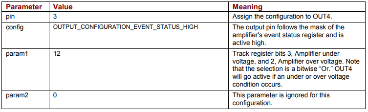
In this example, the mask is a sum of two values:
WriteOutputConfigExt 3,OUTPUT_CONFIGURATION_EVENT_STATUS_HIGH, 12, 0
The parameter values are described below.
No comments to display
No comments to display