
APPENDIX G: ASCII COMMANDS/SERIAL CONTROL
This chapter describes how to configure and operate an amplifier by sending ASCII commands over the serial bus. Contents include:
The Copley ASCII Interface
CME 2 ASCII Command Line Interface Tool
Single-Axis Serial Connection
Multi-Drop Serial Connection
COMPATIBILITY: This chapter applies to Accelnet, Xenus, and Stepnet amplifiers only.
G.1: Copley ASCII Interface
An amplifier’s RS-232 serial bus can be used by an external control application (HMI, PLC, PC, etc.) for setup and direct serial control of the amplifier. The control application can issue amplifier commands from the set of ASCII format commands that make up the Copley Controls ASCII Interface.
For more information, see the Copley ASCII Interface Programmer’s Guide.
G.2: CME 2 ASCII Command Line Interface Tool
As described below, the CME 2 ASCII Command Line Interface tool provides a simple way to enter Copley ASCII commands.
Use the ASCII Command Line Interface to Enter Commands
1 From the Main screen, choose ToolsASCII Command Line to open the tool.
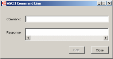
2 Enter an ASCII Command in the Command field.
3 Press the Enter key to send the command to the amplifier. Observe the Response field. If a value is returned, it is preceded by the letter “v.” In the following example, the get command was used to retrieve the amplifier RAM value of variable 0x32 (actual position).
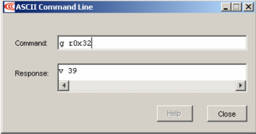
An error code would be preceded by the letter “e.”
TIP: To view an error definition, hold the mouse pointer over the error number.
For more information, see the Copley ASCII Interface Programmer’s Guide and the Copley Amplifier Parameter Dictionary.
G.3: Single-Axis Serial Connection
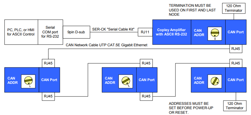
For RS-232 serial bus control of a single axis, set the CAN node address of that axis to zero (0). Note that if the CAN node address is switched to zero after power-up, the amplifier must be reset or power cycled to make the new address setting take effect.

G.4: Multi-Drop Serial Connection
A serially connected amplifier can be used as a multi-drop gateway for access to other amplifiers linked in a series of CAN bus connections. Set the CAN node address of the serially connected amplifier (gateway) to zero (0). Assign each additional amplifier in the chain a unique CAN node address value between 1 and 127. For more information on CAN node address assignment, see CAN Network Configuration . Use 120 Ohms termination on the first and last amplifier.
No comments to display
No comments to display