
9. FAULTS
This chapter shows how to configure the amplifier’s fault latching. Perform the basic steps outlined below. Details follow in the chapter:
1  Click Configure Faults to open Faults Configuration screen.
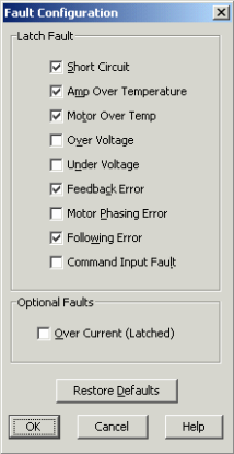
2 Select the faults to latch. See Fault Configuration Parameters
3 Click OK to close screen and save changes to amplifier RAM.
4 On the Main screen, click Save to Flash to avoid losing the changes.
Risk of unexpected motion with non-latched faults.

After the cause of a non-latched fault is corrected, the amplifier re-enables the PWM output stage without operator intervention. In this case, motion may re-start unexpectedly. Configure faults as latched unless a specific situation calls for non-latched behavior. When using non-latched faults, be sure to safeguard against unexpected motion.
Failure to heed this warning can cause equipment damage, injury, or death.
9.1: Fault Configuration Parameters
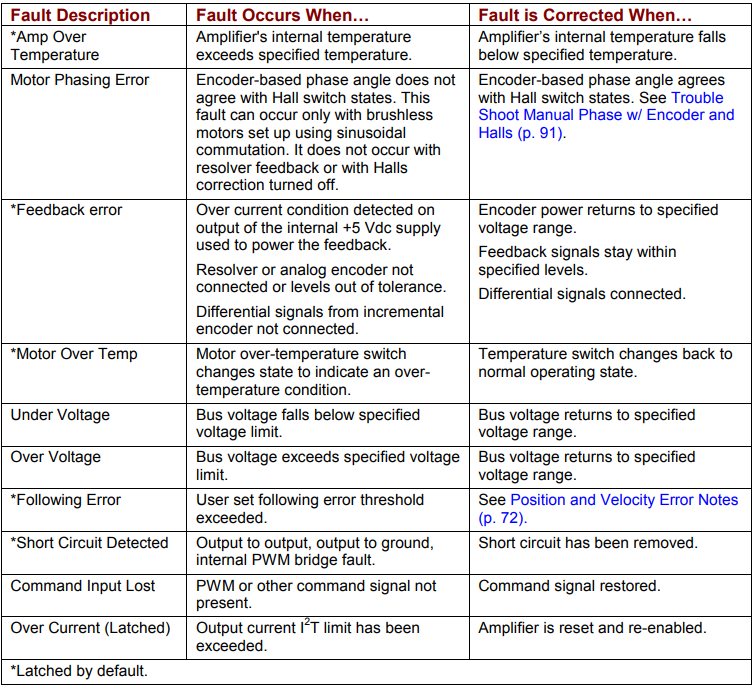
Each of the following faults can be latched by selecting it on the Fault Configuration screen. For more information on latching, see Fault Latching Notes. For details on limits and ranges, see the amplifier documentation.
Note: The list of faults may vary with amplifier model.
9.2: Fault Latching Notes
9.2.1: Clearing Non-Latched Faults
The amplifier clears a non-latched fault, without operator intervention, as soon as the fault condition is corrected.
Risk of unexpected motion with non-latched faults.

After the cause of a non-latched fault is corrected, the amplifier re-enables the PWM output stage without operator intervention. In this case, motion may re-start unexpectedly. Configure faults as latched unless a specific situation calls for nonlatched behavior. When using non-latched faults, be sure to safeguard against unexpected motion.
Failure to heed this warning can cause equipment damage, injury, or death.
9.2.2: Clearing Latched Faults
A latched fault is cleared only after the fault has been corrected and at least one of the following actions has been taken:
• Power-cycle the amplifier
• Cycle (disable and then enable) an enable input that is configured as
Enables with Clear Faults or Enables with Reset
• Access the CME 2 Control Panel and press Clear Faults or Reset
• Clear the fault over the CANopen network or serial bus
9.2.3: Example: Non-Latched vs. Latched Faults
For example, the amplifier temperature reaches the fault temperature level and the amplifier reports the fault and disables the PWM output. Then, the amplifier temperature is brought back into operating range. If the Amp Over Temperature fault is not latched, the fault is automatically cleared and the amplifier’s PWM outputs are enabled. If the fault is latched, the fault remains active and the amplifier’s PWM outputs remain disabled until the faults are specifically cleared (as described above).
9.3: Position and Velocity Error Notes
9.3.1: Error-Handling Methods
In position mode, any difference between the limited position output of the trajectory generator and the actual motor position is a position error. The amplifier’s position loop uses complementary methods for handling position errors: following error fault, following error warning, and a position-tracking window.
To set position error handling parameters for servo amplifiers, see Enter basic Position Loop settings. For stepper amplifiers, see Set Position Limits in Stepper Mode.
Likewise, in velocity or position mode, any difference between the limited velocity command and actual velocity is a velocity error. The amplifier’s velocity loop uses a velocity tracking window method to handle velocity errors. (There is no velocity error fault.)
To set parameters for velocity error handling, see Enter basic Velocity Loop settings
9.3.2: Following Error Faults
When the position error reaches the programmed fault threshold, the amplifier immediately faults. (The following error fault can be disabled.) For detailed information, see Following Error Fault Details
9.3.3: Following Error Warnings
When the position error reaches the programmed warning threshold, the amplifier immediately sets the following error warning bit in the status word. This bit can be read over the CAN network. It can also be used to activate a digital output.
9.3.4: Position and Velocity Tracking Windows
When the position error exceeds the programmed tracking window value, a status word bit is set. The bit is not reset until the position error remains within the tracking window for the programmed tracking time. A similar method is used to handle velocity errors. For detailed information, see Tracking Window Details
9.3.5: Following Error Fault Details
Position Error Reaches Fault Level
As described earlier, position error is the difference between the limited position output of the trajectory generator and the actual position. When position error reaches the programmed Following Error Fault level, the amplifier faults (unless the following error fault is disabled.) As with a warning, a status bit is set. In addition, the fault is recorded in the error log. See Error Log.
Additional responses and considerations depend on whether the fault is non-latched or latched, as described below.
Amplifier Response to Non-Latched Following Error Fault
When a non-latched following error fault occurs, the amplifier drops into velocity mode and applies the Fast Stop Ramp deceleration rate to bring the motor to a halt. The amplifier PWM output stage remains enabled, and the amplifier holds the velocity at zero, using the velocity loop.
Resuming Operations After a Non-Latched Following Error Fault
The clearing of a non-latched following error depends on the amplifier’s mode of operation. Issuing a new trajectory command over the CAN bus, the ASCII interface, or DeviceNet will clear the fault and return the amplifier to normal operating condition.
If the amplifier is receiving position commands from the digital or differential inputs, then the amplifier must be disabled and then re-enabled using the amplifier’s enable input or though software commands. After re-enabling, the amplifier will operate normally.
Amplifier Response to a Latched Following Error Fault
When a latched following error fault occurs, the amplifier disables the output PWM stage without first attempting to apply a deceleration rate
Resuming Operations After a Latched Following Error Fault
A latched following error fault can be cleared using the steps used to clear other latched faults:
• Power-cycle the amplifier
• Cycle (disable and then enable) an enable input that is configured as Enables with Clear Faults or Enables with Reset
• Access the CME 2 Control Panel and press Clear Faults or Reset
• Clear the fault over the CANopen network or serial bus
9.3.6: Tracking Window Details
Proper Tracking Over Time
As described earlier, position error is the difference between the limited position output of the trajectory generator and the actual position. Velocity error is the difference between commanded and actual velocity.
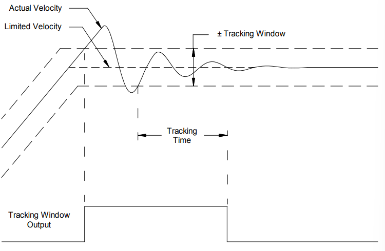
When the position or velocity error exceeds the programmed tracking window value, a status word bit is set. The bit is not reset until the error remains within the tracking window for the programmed tracking time.
Velocity Tracking Illustration
The following diagram illustrates the use of tracking window and time settings in velocity mode.
No comments to display
No comments to display