
3. Controller Module
3.1.Controller Connection
Click the button located in the blue-boxed area in the image to establish a connection with the controller.
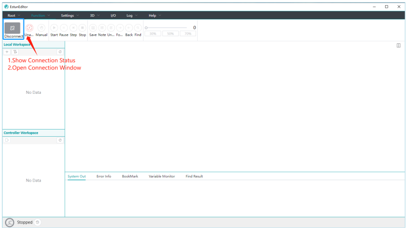
Click to open the connection dialog as shown below.
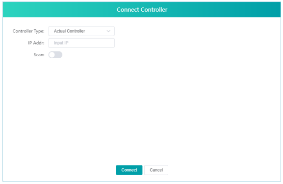
Based on your requirements, select the physical controller and the virtual controller. The connection method is as follows.
3.1.1.Actual Controller
There are two distinct connection methods available for the actual controller, as outlined below:
(1) Known the Actual Controller IP
⚫ Input the corresponding IP address in the IP address field, then click 'Connect'.
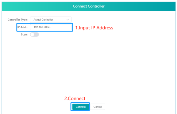
⚫ If the IP address is correct, please wait patiently for a few seconds, and the connection will be established successfully.
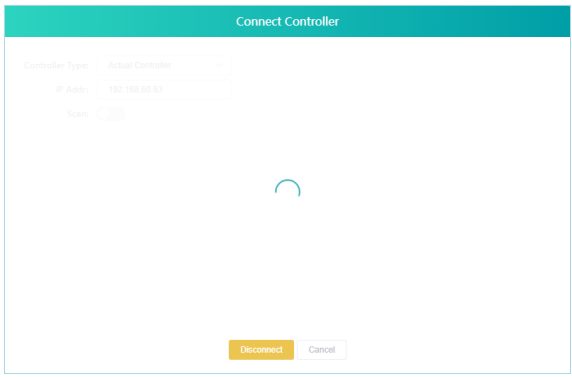
(2) Unknown the Actual Controller IP
⚫ Click on 'Scan' to open the scanning window.
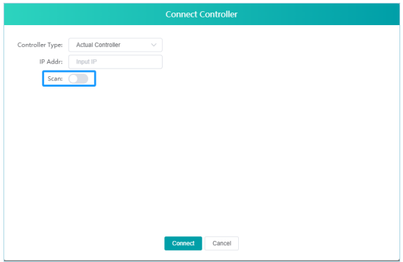
⚫ Click 'Scanning' to search for the current controller's IP.
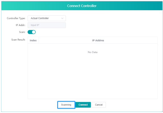
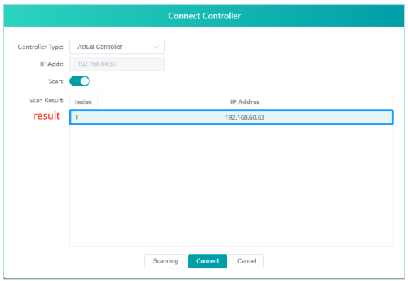
⚫ After scanning and obtaining the results, click 'Connect' to establish a connection with the controller.
This will complete the controller's connection.
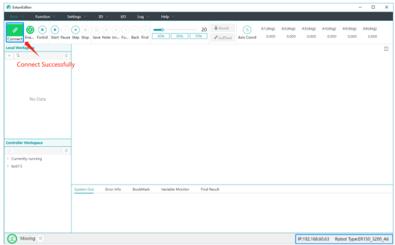
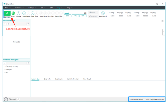
After a successful connection, the connection button will turn green. The blue box in the bottom right corner displays the current controller's IP and robot model.
3.1.2.Virtual Controller
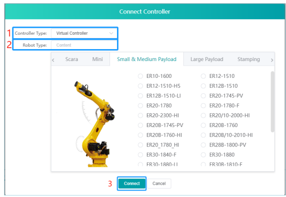
To connect a virtual controller, perform the following steps:
(1) Controller Type: Virtual Controller
(2) Select the appropriate robot model according to your needs.
(3) Click 'Connect' to establish a connection with the virtual controller.
After a successful connection, the connection button will turn green. The blue box in the bottom right corner displays the current controller as a virtual controller, the selected robot model, and the current operational status.
3.1.3 Basic Settings
After connecting to the virtual controller, it will automatically enable and switch to manual mode, while adjusting the robot's initial posture.
Initialized Axis Coordinates: {0,0,0,0,90,0}.
3.2.Controller Disconnection
After establishing a connection with the controller, you can click the "Connect" button to disconnect from the controller. If it is a virtual controller, the background virtual controller will also be closed.

After disconnecting, the status will display ' Disconnect Server Successfully'."

3.3.Robot Control Module
After establishing a connection with the controller, the robot control module allows you to operate the robot.
The robot control module, along with the software's bottom status bar, displays the current status of the controller.
3.3.1Controller Operation Module
The controller operation module, as shown in the diagram,are as follows
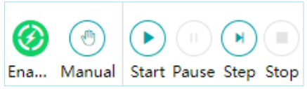
"Enable":enable or disable the controller.
"System Mode": switch between manual and automatic mode.
"Start": start the program execution.
"Pause": pause the program execution.
"Single Step/Cycle":specify whether to run in single step mode or continuous mode.
"Stop": stop the execution and unloads the program.
3.3.2 Status Bar Module
The status bar displays the following information:

(1) Controller running status, which can be divided as "Run", "Pause" or "Stop". The "Start", "Pause", and "Stop" buttons are associated with this running status.
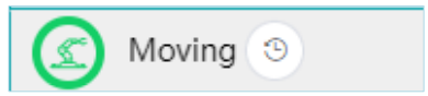
(2) Controller IP address: shows "Virtual Controller" when connected to a virtual controller or the current connected IP address for an actual controller.
(3) Controller model.
(4) Controller Error Messages, the "Clear" button above is used to reset any errors in the controller.

3.4.Introduction to the Main UI Functions of the Editor Software
The following image shows the main UI interface of the software:
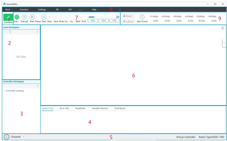
(1) Controller Connection, including physical controllers and virtual controllers.
(2) Local Programs, including text-based programs and graphical programs.
(3) Programs on the controller.
(4) Used primarily for debugging information, displaying error messages, bookmarks for code search, variable monitoring during program execution, program lists, and search results for specific keywords, distributed across each tab.
(5) Status Bar Functions, primarily displaying warning messages, IP address, robot model, and program execution status.
(6) Used primarily for text editing, graphical editing of IO, 3D simulation display, and manual control.
(7) Contains various operation buttons for robot control, editor, and 3D simulation functions.
(8) Primarily consists of drop-down menus, which display corresponding function lists based on the selected item in the menu. It includes functions such as manual control, IO, 3D display, starting the Teach Pendant, and other 3D operations.
(9) Coordinate parameters.
No comments to display
No comments to display