
7. Function
7.1.Manual Control
Manual control necessitates a connection to a controller and is compatible with all robot models within the robot list of the virtual controller. Nevertheless, it is essential to note that actual controller support is exclusively extended to robot models designated with the suffixes -SR, -MI, and -MI/; all other model variants are not eligible for support.
7.1.1.Startup Method
The manual control initiation methods are categorized into two distinct modes, namely:
(1) Function →Manual Control
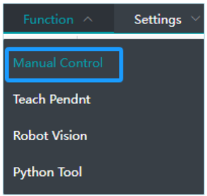
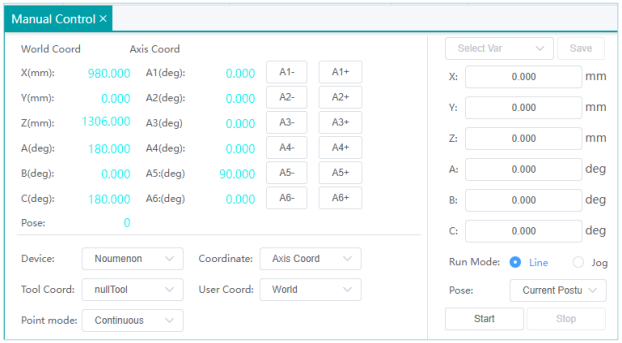
Upon clicking, the interface is displayed as follows:
(2) It is possible to directly invoke the quick manual control window by clicking the button located to the right of the software.
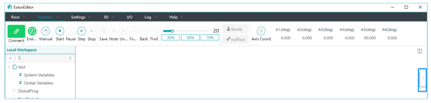
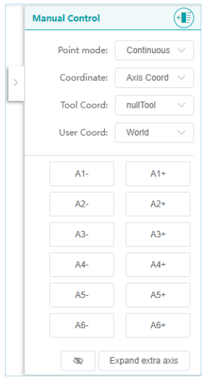
Upon clicking, the interface is displayed as follows:
7.1.2.Coordinate Display
The left side displays the robot's world coordinates, and the right side displays the robot's joint coordinates.
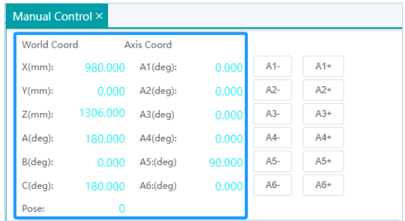
7.1.3.Manual Control
Two columns of buttons are used to control the jog direction of their respective axes. The buttons labeled with '-' denote the negative direction, while those labeled with '+' signify the positive direction.
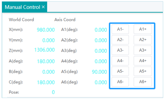
7.1.4.One-Click Motion
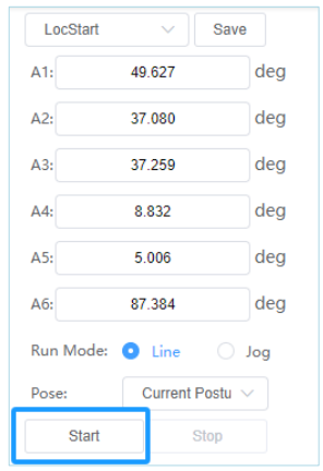
You have the option to perform the following operations by selecting the APOS (Joint Position Type) and CPOS (Coordinate Position Type) variables from the variable file:
(1) You can make necessary adjustments and modifications to the desired point data and then save the changes by using the 'Save' button.
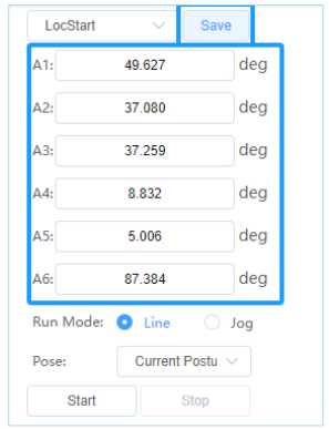
(2) Choose the motion mode: Linear or Joint.
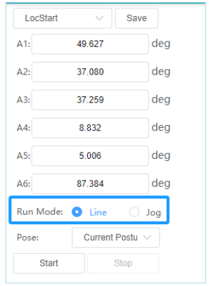
(3) Choose the motion direction: Forward Upward Tilt, Forward Downward Tilt, Backward Upward Tilt, Backward Downward Tilt, etc.
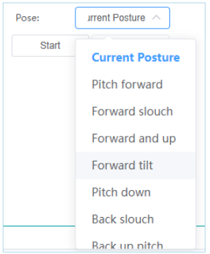
(4) Click on One-click Motion to move the robot to the specified waypoint using the configured settings.
7.1.5.Manual Motion Parameter Settings
(1) Select the object to be configured: Local or External Axes.
(2) Set the tool coordinate system, which is the tool coordinate system of the currently loaded project in the controller.
(3) Set the user coordinate system, which is the user coordinate system of the currently loaded project in the controller.
(4) Set the jog mode: Jogging or Continuous.
(5) Set the motion mode: Axis Coordinates (Joint Motion) or World Coordinates (Path Motion).
7.2. Teach Pendant
Ensure that the controller is already connected.
(1) Ensure that the controller is already connected.
(2) Start the Teach Pendant.
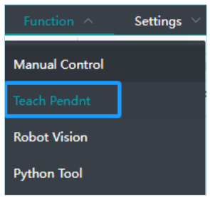
(3) Open the Teach Pendant.
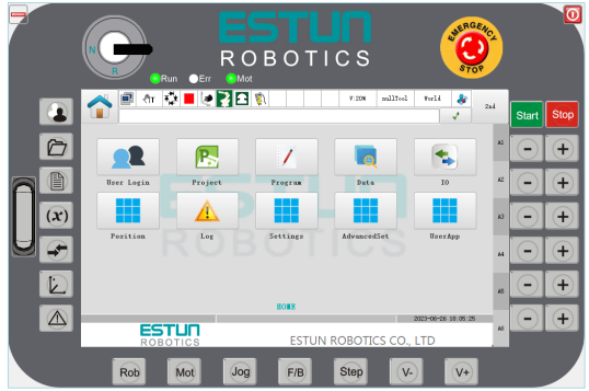
(4)Using the virtual teach pendant while connected to the actual controller:
Step 1: Connect the Ethernet cable to either the EtherCAT1 port or the LAN2 port.
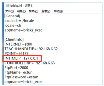
Step 2: Open the brikcs.ini file located at C:\runtime\TP-for-pc.
Step 3: Click on "Edit" and modify INTIMEIP to 192.168.6.68. This allows you to use the virtual teach pendant while connected to the actual controller.
7.3.Machine Vision
Startup Method: Function → Machine Vision
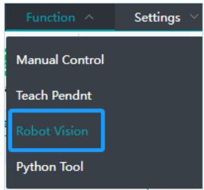
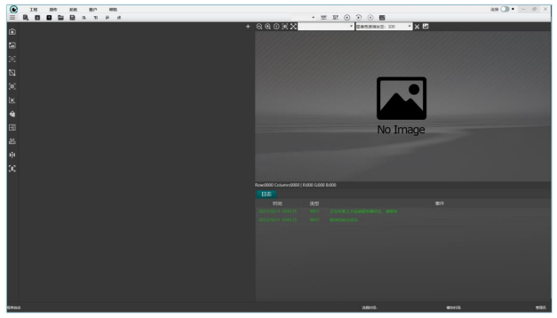
After clicking with the mouse, the corresponding application interface will be launched, enabling direct user interaction.
7.4.Python Tool
Startup Method : Function→Python Tool.
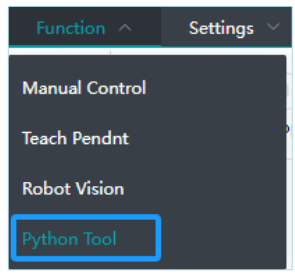
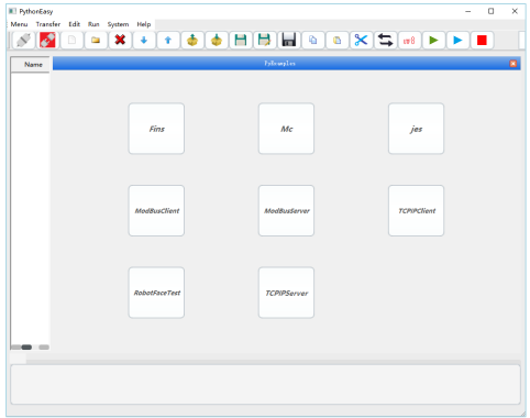
Execute a script development based on requirements after clicking, providing the corresponding application from the given image. Tailor the script according to specified needs.
No comments to display
No comments to display